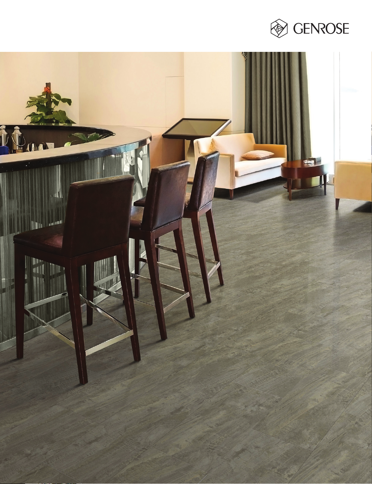
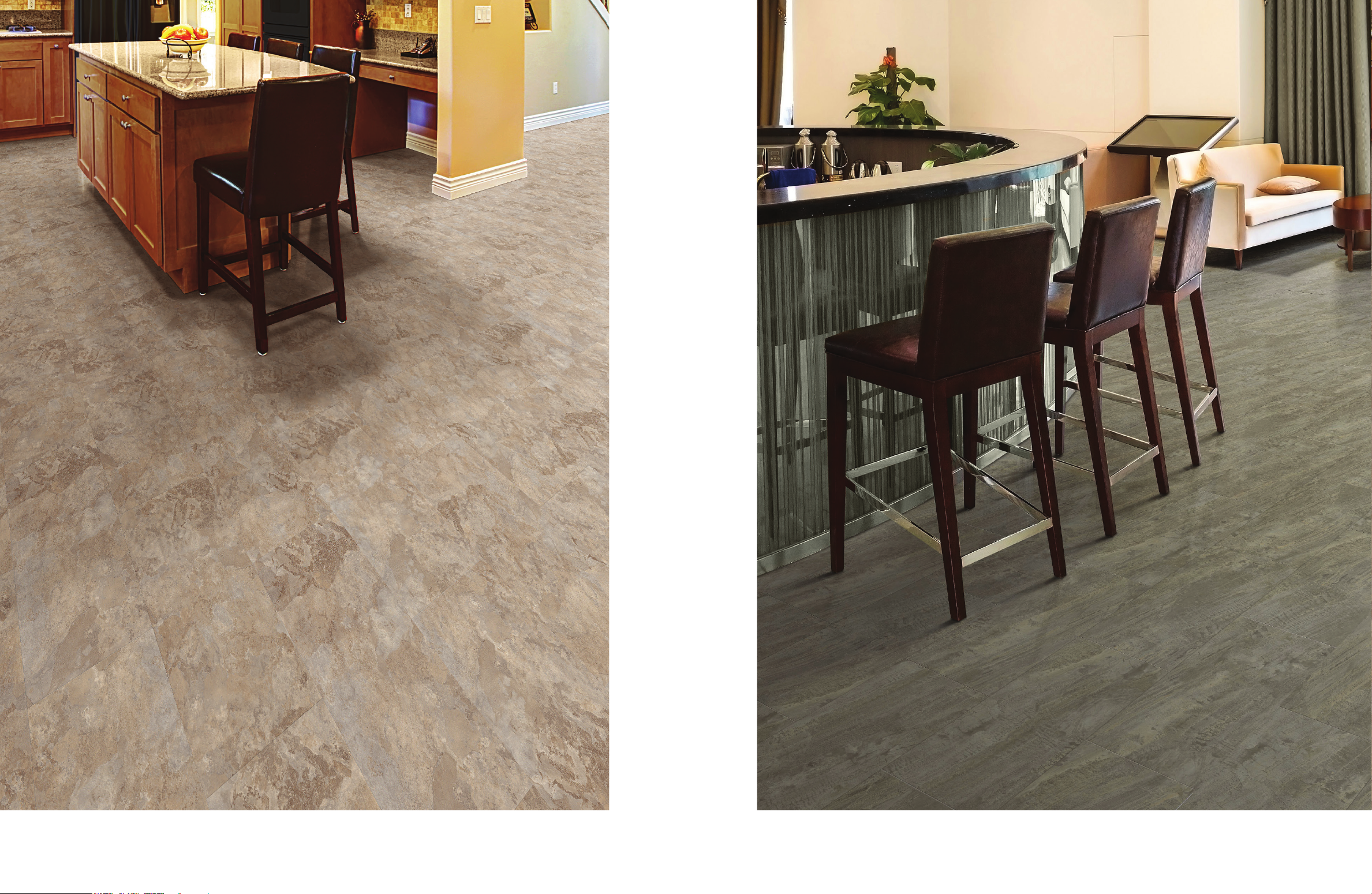
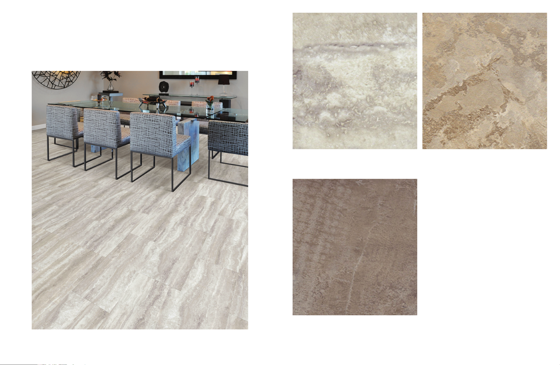
ALBERTA
SPC Vinyl Tile
Contact your sales representative for more information. All material must be inspected prior to installation. Absolutely no claims will be accepted after installation.
QUICKCLICK PRODUCT
INSTALLATION INSTRUCTIONS
SUITABLE SURFACES
Lightly textured or porous surfaces. Well-bonded, solid oors. Dry, clean, well-cured
concrete (cured for at least 60 days prior). Wood oors with plywood on top. Ceramic
or porcelain tiles with grout lines lled with oor leveler. All surfaces must be clean
and dust free.
UNSUITABLE SURFACES
Rough, uneven surfaces including carpet and underlay. Rough, heavily textured and/
or uneven surfaces may telegraph through the vinyl and distort the nished surface.
Do not install this product in areas which are exposed to long term direct sunlight
such as sun rooms or solariums.
WARNING: DO NOT REMOVE OLD RESILIENT FLOORING. THESE PRODUCTS MAY CONTAIN EITHER ASBESTOS
FIBERS OR CRYSTALLINE SILICA, WHICH CAN BE HARMFUL TO YOUR HEALTH.
RADIANT HEATED FLOORS
Can be installed over hydronic radiant heated oors or electric radiant heated oors
that use embedded cables under the suboor. DO NOT INSTALL over any electric
heating mat that is installed on top of the suboor. Do not turn heat above 29˚C
(85˚F). To avoid overheating, the use of an in-oor temperature sensor
is recommended.
PREPARATION
The vinyl tiles should be allowed to acclimatize to room temperature (approx
20˚C/68˚F). Carefully check tiles for any defects before installation. Any tile that has
been installed will be deemed acceptable to the installer. Check that all ITEM NUM-
BERS are the same and that you have purchased sufcient material to complete the
job. Remove any traces of glue or residue from the previous ooring.
New concrete oors need to dry out for at least 60 days prior to installation. Wood
tile oors require a plywood suboor. All nail heads must be driven down below the
surface. Securely nail all loose boards. Scrape, plane or ll uneven boards, holes
or cracks using oor-leveling compound if sub-oor is uneven – over 3.2 mm (1/8”)
within a span of 1.2 m (4’). If installing over existing tile, use a oor levelling
compound to skim coat grout lines. Make sure the oor is smooth, clean, and free of
wax, grease, oil or dust, and sealed as necessary before laying tiles.
TOOLS AND SUPPLIES
Saw, tapping block, rubber mallet, spacers, pencil, tape measure, ruler and safety
goggles.
INSTALLATION
Start in a corner by placing the rst tile with the tongue side facing the wall. Use
spacers around the perimeter of the room, as well as against any xed objects, to
maintain a minimum 8 mm (5/16”) expansion space for rooms up to 12.2 m (40’) in
either direction and a minimum 12 mm (1/2”) expansion space for rooms up to 30 m
(100’) in either direction. The expansion space accounts for the normal movement of
the oor. A T-Molding must be used for commercial spaces measuring greater than
30 m (100’) in either direction. If the ooring is installed in an area falling outside the
normal room temperature range, a T-Molding is required every 7.62 m (25’).
Diagram 1.
NOTE: THIS SPACING MUST ALSO BE MAINTAINED BETWEEN THE FLOOR AND ALL VERTICAL SURFACES,
INCLUDING CABINETS, POSTS, PARTITIONS, DOOR JAMBS AND DOOR TRACKS. YOU WILL ALSO NEED TO USE
TRANSITION STRIPS IN DOORWAYS AND BETWEEN ROOMS. FAILURE TO DO SO MAY CAUSE BUCKLING OR
GAPPING.
To attach your second tile, lower and lock the end tongue of the second tile into the
end groove of the rst tile. Line up edges carefully to ensure a close and tight t.
Using a rubber mallet, lightly tap the top of the end joints where the rst and second
tiles lock together. The tiles should lay at to the oor. Diagram 2.
WARNING: FAILURE TO PROPERLY LINE UP THE END JOINT AND ATTEMPTING TO FORCE IT IN WHILE OUT OF
ALIGNMENT COULD RESULT IN PERMANENT DAMAGE TO THE END JOINT.
Repeat this procedure for each subsequent tile in the rst row. Continue
connecting the rst row until you reach the last full tile.
Fit the last tile by rotating the tile 180º with the pattern side upward and placing it
beside the rst row of tiles with its end up against the far wall. Line a ruler up across
the end of the last full tile and across this new tile. Draw a line across the new tile
with a pencil and cut with a saw. Diagram 3.
Rotate the tile 180º so that it is back to its original orientation. Lower and lock its end
tongue into the end groove of the last full tile. Lightly tap the top of the end joints
with a rubber mallet until the tiles are at on the oor.
You will begin the next row with the off-cut piece from the previous row to stagger
the pattern. Pieces should be a minimum of 200 mm (8”) long and joint offset should
be at least 400 mm (16”). Cut pieces should be no less than 76.2 mm (3”) in width.
Adjust layout for a balanced look. Diagram 4.
To start your second row, tilt and push the new tile’s side tongue into the side groove
of the very rst tile. When lowered, the tile will click into place. Using a tapping block
and rubber mallet, lightly tap the long side of the new tile to lock it with the tiles of
the rst row. The tiles should lay at to the oor. Diagram 5.
Attach the second tile of the new row rst on the long side. Tilt and push tile into
place, making sure edges are lined up. Lower tile to the oor. Using a tapping block
and rubber mallet, lightly tap the long side of the new tile to lock it into place.
Next, lightly tap down on the top of the end joints with a rubber mallet to lock them
together. Continue laying remaining tiles in this manner.
To t the last row, lay a tile on top of the previous row with its the tongue to the wall.
Lay a ruler across the tile so that it is lined up with the side of the tiles of the previous
row and draw a line across the new tile with a pencil. Don’t forget to allow room for
spacers. Cut the tile with a saw and attach into position. Diagram 6.
Door frames and heating vents also require expansion room. First cut the tile to the
correct length. Then place the cut tile next to its actual position and use a ruler to
measure the areas to be cut out and mark them. Cut out the marked points allowing
the necessary expansion distance on each side. Diagram 7.
You can trim for door frames by turning a tile upside down and using a handsaw to
cut away the necessary height so that tiles slide easily under the frames.
Diagram 8.
Remove the spacers once the oor is completely installed.
DISASSEMBLY
To disassemble the oor, tilt an entire row up and disconnect it from the previous
row. Then disconnect each tile by sliding it out horizontally.
CARE AND MAINTENANCE
Avoid exposure to direct sunlight for prolonged periods of time. Use drapes or
blinds to minimize direct sunlight during peak sunlight hours.
Do not expose this oor to temperatures below -20°F or above 150°F (below -20°C
or above 65.5°C).
Water leakage over or around the outer edges of the ooring can damage a wood
suboor, so clean up water as soon as possible.
Sweep regularly to remove surface grit and dust. Use a damp cloth or mop to clean
up any dirt and footprints.
CAUTION: Tiles are slippery when wet.
Never use wax, polish, abrasive cleaners or scouring agents as they may dull or
distort the nish.
High heels can damage oors.
Do not allow pets with unclipped nails to scratch or damage the oor.
Use felt pads under heavy furniture, chairs and tables.
Use doormats at entrance ways to protect the oor from discoloring.
It’s a good idea to save a few tiles in case of accidental damage.
If other trades are in the work area, a oor protector is highly recommended to help
protect the nish of the oor.
WARRANTY
This guarantee is for replacement or refund of the vinyl tile ooring only, not labor
(including the cost of labor for installation of the replacement oor) or costs incurred
with loss of time, incidental expenses or any other damage. It does not cover
damage from improper installation or maintenance (including side or end gapping),
burns, tears, indentations, stains or reduction in gloss level due to normal use and/
or exterior applications. Gapping, shrinkage, squeaks, fadding or structural sub oor
related issues are not covered under this warranty.
Lifetime Residential Warranty
This quality vinyl tile is guaranteed not to wear through or stain for the duration
of your life in your home. From the date of purchase, your oor will be free from
manufacturing defects and will not wear through or permanently stain from common
household stains when installed and maintained according to instructions supplied
with each carton. *Lifetime means 35 years.
20 Year Commercial Warranty
Our 20 Year Limited Commercial Warranty for vinyl tile means that for 20 years, from
the date of purchase, your oor will be free from manufacturing defects and will not
wear through when installed and maintained according to instructions supplied with
each carton. Improper installation or workmanship should be directed to the contrac-
tor who installed the oor.
Claims
This guarantee applies only to the original purchaser and proof of purchase is
required for all claims. Claims for wear must show a minimum dime size area. This
guarantee is pro-rated based on the amount of time the oor has been installed.
If you wish to le a claim under warranty, contact the authorized dealer where the
ooring was purchased.
www.genrose.com
QUICKCLICK PRODUCT
INSTALLATION INSTRUCTIONS DIAGRAMS
7
3
8
4
5
1
6
2
Product Info:
• SPC Vinyl Tile
• Beveled Edge
• Attached 1.5mm High-Density Foam Underlay
• 4.7 mm / 20 mil (.05 mm) Wear Layer
• 40 Years Guarantee: For Residential
• 30 Years Guarantee: For Light/Moderate Commercial Uses
• Check Decor 24 for Stock
Features Test Method Our Value
Size 12.2” W x 24.21” H (310 mm W x 615 mm H)
Thickness 0.19" (4.7 mm)
Wear Layer 20 mil (0.5 mm)
Dimensional Stability and Curling after
Exposure to Low Temperatures EN ISO 23999:2012
Change of -0.02% in manufacturing direction
and -0.03% across manufacturing direction when
exposed to -22°F
(-30°C)
IIC ASTM E492-09 IIC 71
Static Load Resistance ASTM F970-17 Average 0.12 mm residual
indentation
Average Critical Radiant Flux ASTM E648 1.06 Watts/Square Cm
Average Maximum Smoke Density (Flaming) ASTM E662 272
Average Maximum Smoke Density
(Non-Flaming) ASTM E662 96