Gate House R100 User manual

1
Lowes.com
CUSTOM ACCESS RAMP SYSTEM
ITEMS # 0254049, 0254061, 0254072, 0254076,
0016567, 0254099, 0254110, 0054116, 0254117,
0254126, 0254140, 0254150, 0254156
Francais p. 57 Español p. 113
Questions, problems, missing parts? Before returning to your retailer, call our customer
service department at 1-888-442-2923, 8 a.m. - 5 p.m., CST, Monday - Friday.
ATTACH YOUR RECEIPT HERE
Ramp Run
R242
Bottom Run
R100
Landing for Right
& Left Turn
R342
Landing U Turn
R442
Crossbeam
RC536, RC548
Crossbrace
RX536, RX548
Threshold
RT536, RT548
Sq. Leg Extender
RLQ66
Leg Extender
RLT66
Leveling Foot
RB210
MODELS # R100, R242, R342, R442, RB210,
RC536/548, RT536/548, RLT66, RLQ66, RX536/548

2
PRODUCT SPECIFICATIONS
Safety Information............................................................................................................................ 3
Preparation........................................................................................................................................ 3
Package Contents for R242 Ramp Run..................................................................................... 4
Hardware Contents for R242 Ramp Run.................................................................................... 5
Package Contents for R100 Bottom Run.................................................................................. 6
Hardware Contents for R100 Bottom Run ................................................................................ 7
Package Contents for R342 Landing for Right & Left Turn..................................... 8
Hardware Contents for R342 Landing for Right & Left Turn................................................. 9
Package Contents for R442 Landing for U Turn..................................................... 10
Hardware Contents for R442 Landing for U Turn................................................................. 11
Coordinating Pieces ..................................................................................................................... 12
Site Preparation and Foundation............................................................................................... 14
Common System Congurations................................................................................................ 15
Assembly Instructions Steps for all Kits.................................................................................... 16
Assembly Instructions R242 Ramp Run.................................................................................... 18
Assembly Instructions Steps for all Kits................................................................................. 24
Assembly Instructions R342 LANDING for Right & Left Turn............................................ 25
Assembly Instructions R442 LANDING for U Turn................................................................ 34
Assembly Instructions R100 Bottom Run.................................................................................. 41
Adding Decking and Railing...............................................................................................................48
Care and Maintenance........................................................................................................................51
Warranty............................................................................................................................51
Replacement Parts List..................................................................................................................... 53
SPECIFICATIONS
Designed to 100 lbs. per square foot.
Structural posts designed for the greater of
50 lb. per foot on top rail or 200 lb. horizontal
load.
Maximum slope across ramp width:
For 36 in. width ramp: ±7inches
For 48 in. width ramp: ±9inches
Maximum Ramp Slope: 1:7
Recommended Slope: 1:12 (approx. 4.88)
SPECIFICATIONS
A deck height of more than 34 in. from the
post base will require leg extender kits. Max.
height is 49 in.
A deck height of more than 22 in. from the
post base requires diagonal bracing.
The self-leveling foot (Item #0016567, sold
separately) can slope a maximum of ±10° in
any direction.
Designed for use with one of the following
decking materials: 1x6 composite, 2x6 com-
posite, 1x6 wood, 2x6 wood.
TABLE OF CONTENTS

3
Lowes.com
PREPARATION
WARNING
CAUTION: Installation should be performed in temperatures ranging from 208F to 1008F
Please read and understand this entire manual before attempting to assemble, operate or install
the product.
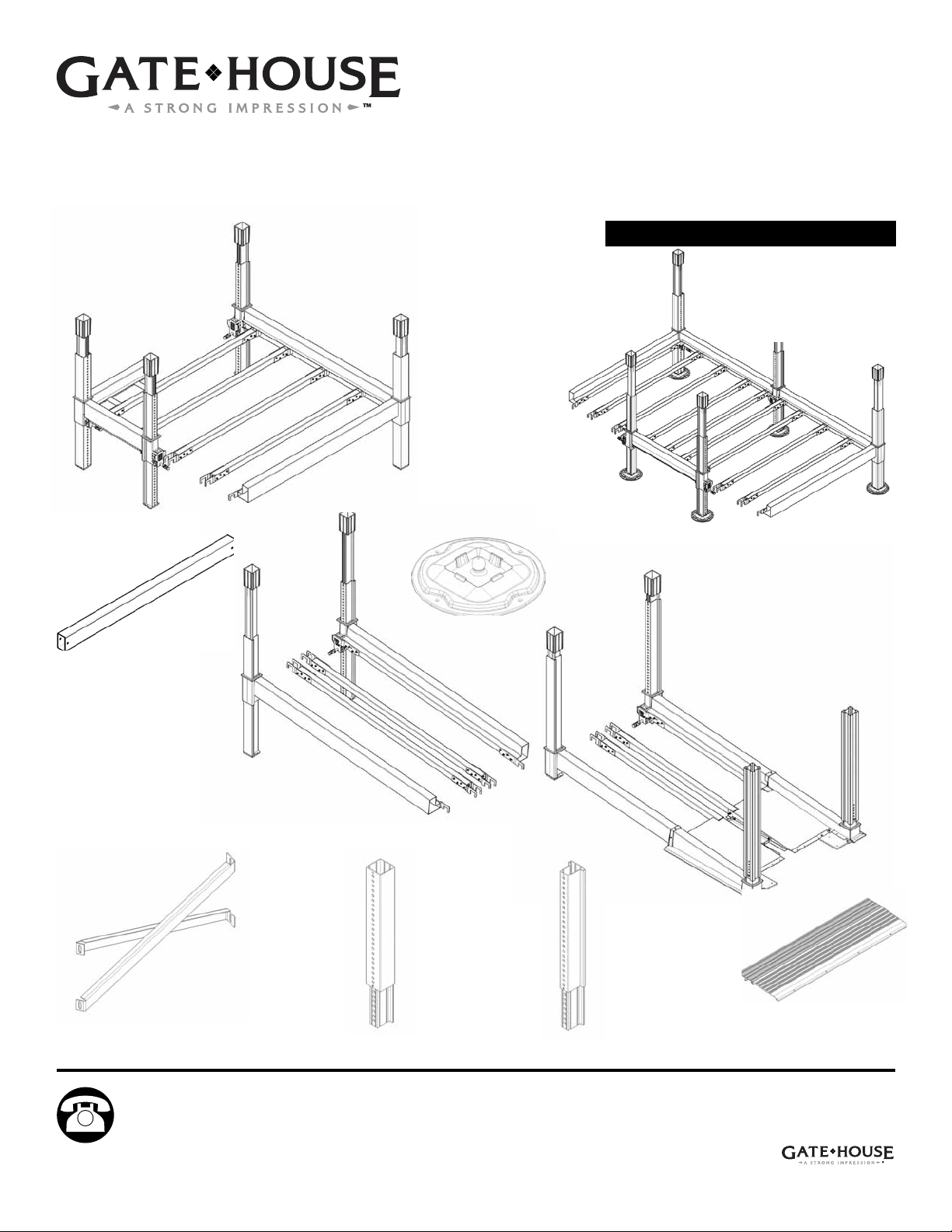
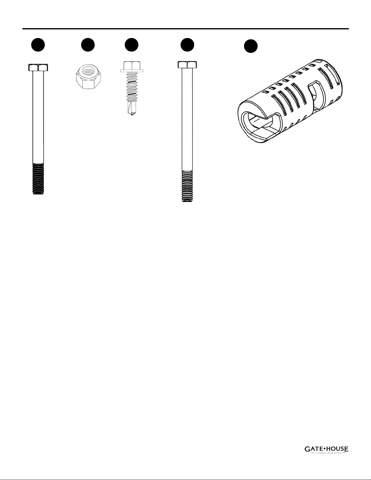
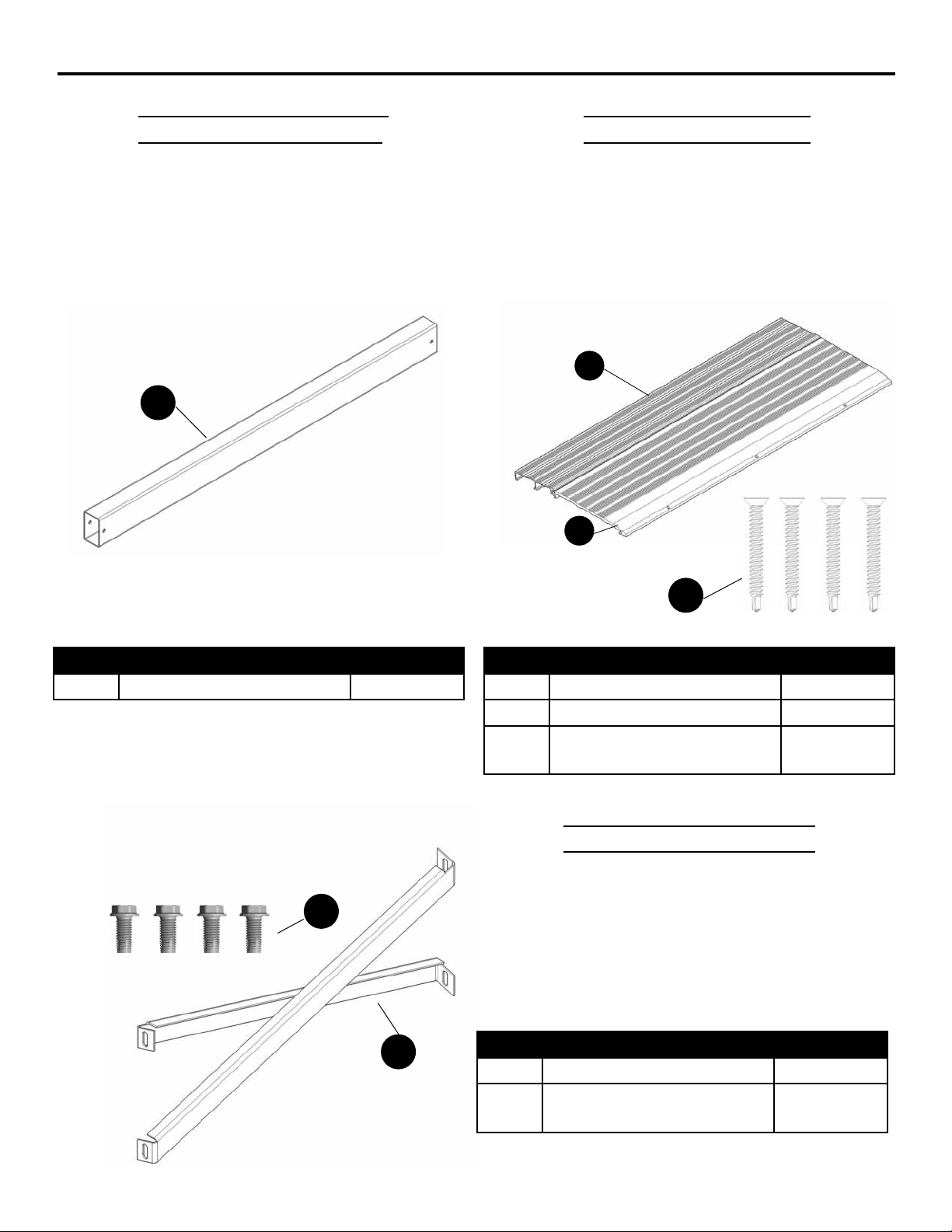
Before beginning assembly of product, make sure all parts are present. Compare parts with package
contents list and hardware contents list. If any part is missing or damaged, do not attempt to
assemble the product; call 1-888-442-2923.
Tools Required for Assembly: Safety Glasses, Gloves, Tape Measure, Level, Carpenter’s Square,
Drill with Phillips #3 bit and 3/8 in. hex nut driver, Hex Key, Utility Knife or Scissors, Combination
Wrenches or Ratchet Wrench with socket sizes 7/16 in., 1/2 in., 3/4 in. Adjustable Wrench optional.
Please consult anchor manufacturer for any additional tools required for securing chosen anchors
(sold separately). Electric impact driver and angle meter recommended but not required.
Additional tools may be required for installation of decking and railing.
• Based on the International Building Code (IBC) 2012, American Society of Civil Engineers
(ASCE) 7-10 design code and National 2010 ADA Standards for Accessible Design, the Custom
Access Ramp System (CARS) has been designed to 100 lbs. per square foot vertical load and
the greater of 50 lb. per foot on top rail or 200 lb. horizontal load. Consult chosen railing for load
specications. Local building codes should be veried before construction. Consult a qualied
designer for footing details to extend max. rise.
• Can be congured to meet National 2010 ADA Standards for Accessible Design.
• Design of the ramp does not take into account impact from weight of snow accumulations
falling from adjacent surfaces or snow loads in excess off 100 lbs.
• Posts require a minimum foundation and anchorage sufcient to support 1600 lbs vertical
load. The landing area must be a solid, level surface. It is recommended that the adjustable post
support brackets of the item# 0254049 bottom run shall be connected to a single concrete footing
on which they both sit. It is the responsibility of the owner or qualied installer to verify soil condi-
tions and requirements for compliance with local codes.
• Actual soil conditions at ramp location shall be veried and the specic footing requirements
shall be designed by a qualied designer. For site specic conditions contact a qualied designer
(i.e. poor soil conditions, steep hill sides, and special loading conditions.)
• The top of the ramp assembly shall be connected to a supporting structure that is capable of
supporting all longitudinal and lateral ramp loads as required by the 2012 IBC and local building
codes.
• The design of the ramp assembly as set forth herein pertains only to the ramp components
and assembly as manufactured by Americana Building Products. The design of and attachment
to supporting structural elements are outside of the scope of this guide. It shall be the Owner and
Installer’s responsibility to provide sound supporting structure and attachment and to consult with
qualied individuals where the design or verication of such components is required.
• It shall be the Owner and Installer’s responsibility to verify that local building code require-
ments are met and that proper permits are obtained prior to the installation. Professional engi-
neering services may be required. Contact a Lowe’s representative for professional engineering
options if required. Hurricane tie downs are available for instances where local code requires
them. Please call 1-888-442-2923 for more information.
SAFETY INFORMATION

8
PACKAGE CONTENTS: Landing for Right & Left Turns R342
PART DESCRIPTION QUANTITY
A6 Landing Leg (A6) Assem-
bly
1
A7 Landing Leg (A7) Assem-
bly
1
A8 Landing Sq. Leg (A8) As-
sembly
2
C Sleeve Cap 4
G Side Rail 1
H Side Rail Bracket (pre-
assembled)
1
I Side Rail Bracket (pre-
assembled)
1
J Support Joist 4
K Support Joist Bracket 8
PART DESCRIPTION QUANTITY
P Landing Crossbeam 65.25
in.
1
Q Landing Crossbeam 12.5
in.
1
R Landing Crossbeam 24.5
in.
1
S Beam Cover 65.5 in. 1
T Beam Cover 13.5 in. 2
U Beam Cover 25.5in. 2
V Beam Cover Bracket 2
PART SOLD SEPARATELY QUANTITY
RC536 or
RC548
Crossbeam 36 in. or
48 in.
Need 1

9
Lowes.com
HARDWARE CONTENTS (shown actual size) Landing for Right & Left Turns R342
AA BB EE
1/4 x 3 in.
Bolt
Qty. 4
#14 x 1 in.
HWH #3
Tek Screw
Qty. 104
Handle
Qty. 4
PP
FF
1/4 in. x 3 1/4 in.
Bolt
Qty. 2
1/4 Lock Nut
Qty. 6

12
A2
A3
COORDINATING PIECES
Crossbeam 36 in. RC536
Crossbeam 48 in. RC548
Needed for:
Bottom Run R100
Ramp Run R242
Landing Right or Left Turn R342
Landing U Turn R442
Threshold 36 in. RT536
Threshold 48 in. RT548
(2 Thresholds needed per project: one at entry
of Bottom Run and one at end of ramp section)
Can attach to:
Bottom Run, Ramp Run, Landing for Right &
Left Turn, Landing for U Turn
Cross Brace 36 in. RX536
Cross Brace 48 in. RX548
Needed for:
Ramp Run R242 when either post spans more
than 22 in. from post base to top of crossbeam
Z
OO
A1 PART DESCRIPTION QUANTITY
A1 Cross Brace Angle 2
OO Bolt, 9/16 x 1-1/4 in. HWH
TapFlex
4
PART DESCRIPTION QUANTITY
A2 Threshold Plank (A) 1
A3 Threshold Plank (B) 1
NN Screw, #8-18 x 1-1/2 in.
PFH #2 Tek
4
PART DESCRIPTION QUANTITY
Z Crossbeam 1
NN
Not to size
Not to size

13
Lowes.com
Leveling Foot RB210
Needed for:
Posts placed on slopinsg surface
T Leg Extender RLT66
Needed for: T Leg Post more than 28 in. from
post base to deck height on Landing for Right &
Left Turn R342 or Landing for U Turn R442
Square Leg Extender RLQ66
Needed for: Square Post more than 28 in. from
post base to deck height on Landing for Right &
Left Turn R342 or Landing for U Turn R442
COORDINATING PIECES
PART DESCRIPTION QUANTITY
WLeg Attachment 1
Y Square Leg Extender 1
CC Screw, #8-18 x 1 in. PFH
#2 Tek
1
PART DESCRIPTION QUANTITY
WLeg Attachment 1
X Leg Extender 1
CC Screw, #8-18 x 1 in. PFH
#2 Tek
1
X
W
Y
W
CC
Pre-assembled Pre-assembled
A4
QQ
PART DESCRIPTION QUANTITY
A4 Leveling Foot 1
QQ Screw, Wood 3 in. Slotted
Flat Head
2
Not to size
CC

14
(Materials NOT supplied with kits)
Note: Site preparation is required for this ramp. Placing posts on a footing is highly recommended.
Without footings, settling could occur. The manufacturer is not responsible for replacing parts dam-
aged or property lost due to incorrect assembly.
Note: Complete the site preparation and footings before unpacking parts and beginning assembly.
To prepare ramp site, follow the steps below:
1) Consult local building codes before construction.
2) Before any digging, check with local utilities to determine location of buried cables, pipes, etc.
3) Posts require a minimum foundation and anchorage sufcient to support 1600 lbs vertical load. The
landing area must be a solid, level surface. It is recommended that the adjustable post support brack-
ets of the item# 0254049 bottom run shall be connected to a single concrete footing on which they
both sit. It is the responsibility of the owner or qualied installer to verify soil conditions and require-
ments for compliance with local codes. Actual soil conditions at ramp location shall be veried and
the specic footing requirements shall be designed by a qualied designer. For site specic conditions
contact a qualied designer (i.e. poor soil conditions, steep hill sides, and special loading conditions.)
4) Anchoring the ramp: Count base types on your complete unit and purchase anchors required.
Recommended anchors for concrete applications: 1/4 in. diameter x 3 in. long concrete screws
Recommended anchors for wood applications: 1/4 in. diameter x 3 in. long into wood support joists
5) Begin installation with section that attaches to building.
NOTE: To rm and level rst section, attach threshold to a supporting structure that is capable
of supporting all longitudinal and lateral ramp loads as required by the 2012 IBC and local
building codes.
SITE PREPARATION AND FOUNDATION
Standard Post Base Optional Leveling Foot

15
Lowes.com
Landing Right Turn
R342
To join kits switch
A5 T Leg Assembly
with A7 Landing
Leg
COMMON SYSTEM CONFIGURATIONS
Landing Left Turn
R342
Landing U Turn
R442
BEFORE ASSEMBLY: Layout posts in a rough approximation of desired
conguration. Refer to planning guide at Lowes.com/ramps for more details.
NOTE: R100 Bottom Run and R242 Ramp Run have two A5 T Leg Assemblies
that accept a crossbeam. When joining a Bottom Run or Ramp Run to a land-
ing, one A5 T Leg Assembly must be switched with a Landing Leg Assembly
(A6 or A7) to accept a crossbeam on two sides.
NOTE: Congurations can be combined as needed.
NOTE: Start the ramp with the section next to the building and secure with a
Threshold (RT536 or RT548).
To join kits switch
A5 T Leg Assembly
with A7 Landing
Leg
To join kits switch
A5 T Leg Assembly
with A6 Landing
Leg
Landing U Turn
R442

16
ASSEMBLY INSTRUCTIONS: FOR ALL KITS
Hardware Used
2. If using Leveling Foot RB210, position under post
and press down until the lock pops. Pivot post until two
holes in foot are completely visible. Install two #8 x 3 in.
screws (QQ) to lock Leveling Foot on post assembly. It
will still pivot.
3 in. Slotted Flat Head Screw
QQ
2
x 2
1. Before beginning assembly, open all kits and compare package contents with package contents
and hardware contents lists to be certain all parts are accounted for. Next, identify all posts: the A5 T
Leg Assemblies, A6 Landing Leg (A) Assemblies, A7 Landing Leg (B) Assemblies, and the A8 Land-
ing Sq. Leg Assemblies. Layout posts where needed. Refer to the Common System Congurations
section on page 15.

17
Lowes.com
3. Holding rmly in place, attach a support joist
bracket (K) to a support joist (J) with #14 x 1 in.
HWH #3 Tek Screws (EE).
Recommended Tool (not included): drill with 3/8 in.
hex nut driver
Hardware Used
#14 x 1 in. HWH #3 Tek Screw x 8
EE
Hardware Used
4. Attach another support joist bracket (K) to the other
end of the support joist (J) using #14 x 1 in. HWH #3 Tek
Screws (EE).
NOTE: Only attach support joist brackets (K) to both
ends of the support joists (J) for R242 Ramp Runs, R342
Landings for Right & Left Turns and R442 Landings for
U Turns (see Fig. 3A). Only attach support joist brackets
(K) to one end of the support joists (J) for R100 Bottom
Runs (see Fig. 3B).
Repeat steps 3 and 4 for all remaining joists.
#14 x 1 in. HWH #3 Tek Screw
EE
R242, R342, R442 Joists R100 Joists
3
4
ASSEMBLY INSTRUCTIONS: FOR ALL KITS
Fig. 3a Fig. 3b

24
ASSEMBLY INSTRUCTIONS FOR ALL KITS
Hardware Used17. When the top of a crossbeam is more
than 22 in. from the bottom of the post, cross
braces RX536/RX548 (sold separately) must
be attached. Attach the cross brace angles
(A1) to the posts with 9/16 x 1-1/4 in. HWH
TapFlex bolts (OO). Attach cross braces at
rst hole under the sleeve on the posts.
OO Bolt, 9/16 x 1-1/4 in. HWH TapFlex x 4
18. When the top of the crossbeam is 34 in. or higher from the bottom of the post, leg extenders
RLT66/RLQ66 (sold separately) must be attached. Remove pre-assembled #8-18 x 1 in. PFH #2 Tek
Screw (CC) from extender, slide out adjustable post support and insert leg extender RLT66/RLQ66
(X/Y) into the post. Adjust height and secure with the Tek Screw (CC).
17
More
than 22
in.
18

ASSEMBLY INSTRUCTIONS
25
Lowes.com
Hardware Used
19. Layout side rail (G). Pivot side rail brackets (H
and I) (pre-assembled) to match position shown.
Attach with #14 x 1 in. screws (EE). Tighten the
pre-assembled screws.
NOTE: DO NOT OVER-TORQUE SCREWS.
Recommended Tool (not included): drill with 3/8 in.
hex nut driver
#14 x 1 in. HWH #3 Tek Screw
EE
Landing Right & Left Turn R342
20. Identify posts and lay them out to match diagram for
your turn. Also refer to the Common Congurations sec-
tions on page 15.
NOTE: The T Leg Assembly (A5) is not included with the
R342 Landing for Right & Left Turn. It is included with
the R242 Ramp Run or R100 Bottom Run.
Post Diagram, left turn from starting point
19
20b
20a
Post Diagram, right turn from starting point

ASSEMBLY INSTRUCTIONS
26
21. Assemble straight line of posts.
Attach crossbeam RC536/RC548 (Z) (sold separately)
to Landing Leg Assembly (A6) with 1/4 in. x 3 in. bolt
(AA) and 1/4 in. nut (BB).
Add T Leg Assembly (A5) to other side of crossbeam
RC536/RC548 (Z) (sold separately).
NOTE: Position nut (BB) to face upward on ramp.
Recommended Tool (not included): Ratchet wrench
with 7/16 in. socket
Hardware Used
x 2
x 2
AA
BB
1/4 x 3 in. Bolt
1/4 Nut
Landing Right & Left Turn R342
21

ASSEMBLY INSTRUCTIONS
27
Lowes.com
Landing Right & Left Turn R342
22. Attach Landing crossbeam (Q or R) to back of Land-
ing Leg (A6) Assembly with 1/4 in. x 3 in. bolt (AA) and
1/4 in. nut (BB). Add Landing Sq. Leg (A8) Assembly to
crossbeam with 3 in. bolt (AA) and nut (BB).
NOTE:
Crossbeam (Q) 24-1/2 in. used on ramp width 36 in.
Crossbeam (R) 12-1/2 in. used on ramp width 48 in.
Recommended Tool (not included): Ratchet wrench with
7/16 in. socket
Hardware Used
x 2
x 2
AA
BB
1/4 x 3 in. Bolt
1/4 Nut
NOTE: If coming from an R242 Ramp Run, use this
assembly to complete steps 8-13. Then continue with
step 23.
23. Attach handle (PP) to all post pinss.
Adjust level of crossbeams as needed by pulling pinss
and moving up or down.
Remove handle for safety after installation is complete.
Hardware Used
PP Handle x 3
23
22

ASSEMBLY INSTRUCTIONS
28
Landing Right & Left Turn R342
Hardware Used
x 1
AA
BB
1/4 x 3 in. Bolt
1/4 Nut x 2
24. Assemble corner posts.
Attach Landing crossbeam (P) to Landing Sq. Leg As-
sembly (A8) with 1/4 in. x 3 in. bolt (AA) and 1/4 in. nut
(BB).
Attach the other side of Landing Crossbeam (P) to the
left side of Landing Leg (A7) Assembly for a right turn or
the right side of (A7) for a left turn. Secure with a 3-1/4
in. bolt (FF) and nut (BB). Position nut (BB) inside land-
ing.
Recommended Tool (not included): Ratchet wrench with
7/16 in. socket
1/4 in. x 3 1/4 in.Bolt
FF
x 1
Hardware Used
BB 1/4 Nut x 2
25. Attach crossbeam RC536/RC548 (Z) (sold separately)
to Landing Leg (A7) Assembly with 1/4 in. x 3-1/4 in. bolt
(FF) and 1/4 in. nut (BB).
Add T Leg (A5) Assembly to other side of crossbeam (Z)
with 3 in. bolt (AA) and nut (BB).
Recommended Tool (not included): Ratchet wrench with
7/16 in. socket
1/4 in. x 3 1/4 in.Bolt
FF
x 1
x 1
AA
1/4 x 3 in. Bolt
Post Placement for Left Turn
A8
25
24
Post Placement for Left Turn
Left turn A7.
For right turn,
attach to other
side.

ASSEMBLY INSTRUCTIONS
29
Lowes.com
26. Hang support joist (J) over crossbeams.
Space remaining three joists 12 in. to 16 in. apart.
27. Lock side rail (G) over crossbeams.
Landing Right & Left Turn R342
Diagram for Left Turn
27
26

ASSEMBLY INSTRUCTIONS
30
Landing Right & Left Turn R342
28. If section is next to house/deck, refer to step 14.
Install Threshold Kit RT536 or RT548.
Pull handles (PP) and raise/lower crossbeam (Z or P)
to level the entire platform.
Recommended Tool (not included): Level.
29. Finish leveling all crossbeams (Z, P, Q, R) by
turning the ne-adjustment set screw in each sleeve
using a hex key (not included). Turn the screw clock-
wise to raise the crossbeam or counterclockwise to
lower it.
Recommended Tools (not included): hex key, level.
28
29

ASSEMBLY INSTRUCTIONS
31
Lowes.com
Landing Right & Left Turn R342
30. Attach Beam cover (S) to Landing crossbeam (P)
with #14 x 1 in. white screws (EE).
Recommended Tool (not included): drill with 3/8 in. hex
nut driver
Hardware Used
#14 x 1 in. HWH #3 Tek Screw x 8
EE
31. Attach beam cover (T or U) to crossbeam (Q or R)
with #14 x 1 in. white screws (EE).
NOTE:
Beam cover (T) 13-1/2 in. used on ramp width 48 in.
Beam cover (U) 25-1/2 in. used on ramp width 36 in.
Recommended Tool (not included): drill with 3/8 in. hex
nut driver
Hardware Used
#14 x 1 in. HWH #3 Tek Screw x 3
EE
30
31

ASSEMBLY INSTRUCTIONS
32
Landing Right & Left Turn R342
32. Attach two beam cover brackets (V) to support joist
(J) with two #14 x 1 in. screws (EE) each. Position one
bracket next to T Leg Assembly (A5) and one next to
support joist bracket (K).
Recommended Tool (not included): drill with 3/8 in. hex
nut driver
Hardware Used
#14 x 1 in. HWH #3 Tek Screw x 4
EE
Hardware Used
#14 x 1 in. HWH #3 Tek Screw x 2
EE
33. Attach remaining beam cover (T or U) to crossbeam
(Q or R) with three #14 x 1 in. white screws (EE).
NOTE:
Beam cover (T) 13-1/2 in. used on ramp width 48 in.
Beam cover (U) 25-1/2 in. used on ramp width 36 in.
Recommended Tool (not included): drill with 3/8 in. hex
nut driver
32
33
This manual suits for next models
25
Other Gate House Household Appliance manuals
Popular Household Appliance manuals by other brands

Conveying & Hoisting Solutions
Conveying & Hoisting Solutions 4100 Operating & assembly instructions

Sharper Image
Sharper Image 204904 user guide

Knightsbridge
Knightsbridge SK006 Installation & maintenance manual

ROBINHOOD
ROBINHOOD IC 300 Deluxe Installation and operating instructions

Singer
Singer SEUBF-80 instruction manual

Taurus
Taurus Textile Care MCL300 Instructions for use