impinj SPEEDWAY IPJ-R1000 User manual

Software Release 2.4.0 Doc Rev 1.1 02-07 www.impinj.com
Copyright © 2007, Impinj, Inc.
Im
p
in
j
, S
p
ee
d
wa
y
, and GrandPrix are either re
g
istered trademarks or trademarks of Im
p
in
j
, Inc.
USER GUIDE
USER GUIDE
Speedway Reader IPJ-R1000 for UHF Gen 2 RFID
EPCglobal™ certified for dense-reader operation
High-performance software radio architecture for
maximum flexibility
Monostatic antennas for low-cost deployment
Patented interference rejection combined with
high sensitivity ensures highest possible read
reliability
Gen 2 certified for compliance and
interoperability

Speedway Reader IPJ-R1000 for UHF Gen 2 RFID
2
Overview
The EPCglobal™-certified Speedway™ IPJ-R1000 reader is a stationary UHF Gen 2 RFID tag reader that provides network
connectivity between tag data and enterprise system software.
A key element of Impinj's GrandPrix™ RFID system solution, the Speedway reader is the first high-performance reader
designed from the ground up to support the EPCglobal Gen 2 standard in its entirety, including: the accommodation of 640
kbps tag-to-reader data rates, robust performance in dense-reader environments (without the requirement for network
synchronization), the elimination of ghost reads, and more. Combined with an extensible architecture that supports seamless
integration of field-upgradeable, third party application software, the Speedway reader is the most adaptable reader solution
available today.
This user guide provides instructions on how to install, connect, configure, operate, upgrade, and troubleshoot Speedway
readers. It assumes the user is familiar with appropriate networking facilities, the EPCglobal Gen 2 specification, and general
principles of RFID system management.
Important The user guide only covers readers having part numbers in the following format:
IPJ-R1000-USA-N-NN-NN-NNN, IPJ-R1000-EU1-N-NN-NN-NNN, and IPJ-R1000-AS1-N-NN-NN-NNN.
EPCglobal™ Dense-Reader Certified
Blah, blah, blah
Blah, blah, blah
Blah, blah, blah

Speedway Reader IPJ-R1000 for UHF Gen 2 RFID
3
Federal Communications Commission (FCC) Compliance
This equipment has been tested and found to comply with the limits for a Class B digital device, pursuant to Part 15 of the FCC
Rules. These limits are designed to provide reasonable protection against harmful interference in a commercial environment.
This equipment generates, uses, and can radiate radio frequency energy and, if not installed and used in accordance with the
instructions, may cause harmful interference to radio communications. However, there is no guarantee that interference will not
occur in a particular installation. If this equipment does cause harmful interference to radio or television reception, which can
be determined by turning the equipment off and on, the user is encouraged to try to correct the interference by one or more of
the following measures:
•Reorient or relocate the receiving antenna
•Increase the separation between the equipment and receiver
•Consult the dealer or a qualified radio/TV technician for assistance
Caution Changes to this product or modifications not expressly approved by the party responsible for compliance could
void the user's authority to operate the equipment per FCC Part 15.
Industry Canada (IC) Compliance
Operation is subject to the following two conditions: (1) this device may not cause interference, and (2) this device must accept
any interference, including interference that may cause undesired operation of the device.
This device has been designed to operate with the antenna(s) listed in section 2.5 and having a maximum gain of 6 dB.
Antennas not included in this list or having a gain greater than 6 dB are strictly prohibited for use with this device. The
required antenna impedance is 50 ohms.
To reduce potential radio interference to other users, the antenna type and its gain should be so chosen that the equivalent
isotropically radiated power (EIRP) is not more than that permitted for successful communication.
Note: The term “IC:” before the radio certification number only signifies that Industry of Canada technical specifications were
met.
CE Marking and European Economic Area (EEA)
RFID devices designed for use throughout the EEA must have a maximum radiated transmit power of 2W ERP in the
frequency range of 865.6–867.6 MHz. For other EEA restrictions on RFID device use, please refer to the Impinj Declaration of
Conformity (DoC) located at http://rfid-support.impinj.com
Before You Begin
Warning Please read this document in its entirety before operating the Speedway reader, as serious personal
injury or equipment damage may result from improper use.
Unauthorized opening of the Speedway reader enclosure voids the warranty.
!

Speedway Reader IPJ-R1000 for UHF Gen 2 RFID
4
Table of Contents
1. Regions of Operation.............................................................................................................6
1.1. Operation in North America ...........................................................................................6
1.2. Operation in Europe.......................................................................................................6
1.3. Operation in Taiwan.......................................................................................................6
2. Setting Up the Speedway Reader .........................................................................................7
2.1. System and Equipment Requirements ..........................................................................7
2.2. Speedway Reader I/O Ports & Status............................................................................8
2.3. Mounting the Speedway Reader....................................................................................9
2.4. Connecting Power .......................................................................................................10
2.5. Connecting the Antenna(s) ..........................................................................................10
2.5.1. FCC and Industry Canada................................................................................................................................10
2.5.2. European Economic Area................................................................................................................................11
3. Communicating with the Speedway Reader........................................................................12
3.1. Preparing Serial Connectivity.......................................................................................13
3.2. Preparing Ethernet (TCP/IP) Connectivity ...................................................................14
3.3. Mach1 Interface ...........................................................................................................14
4. Network Configuration .........................................................................................................15
5. Speedway Reader Settings .................................................................................................16
6. Using the Speedway Reader ...............................................................................................20
6.1. Operation Screen—Monitoring Inventory Results........................................................20
6.2. Operation Screen—Filters ...........................................................................................20
6.3. Inventory Filter Screen.................................................................................................21
6.4. Tag Access Screen......................................................................................................23
6.5. Version Screen ............................................................................................................25
7. Firmware Upgrade...............................................................................................................26
7.1. Upgrade Methods ........................................................................................................27
7.2. Preparing the Upgrade Image......................................................................................27
7.3. The Upgrade Configuration Metafile ............................................................................27
7.4. Preparing the Upgrade Configuration Metafile.............................................................28
7.5. Image Management Command ...................................................................................29
7.5.1. Command Line Interface Upgrade ..................................................................................................................29
7.5.2. GUI Upgrade...................................................................................................................................................29
7.5.3. Factory Default Restoration.............................................................................................................................31
7.5.4. Fallback to Previous Image .............................................................................................................................31
7.5.5. Query the Upgrade Status................................................................................................................................31
7.5.6. Background Execution of Image Management Commands ............................................................................31
7.6. Upgrade Examples ......................................................................................................32
7.7. Metafile Example .........................................................................................................33
7.8. Other URI Examples....................................................................................................33
7.9. Detailed Upgrade Behavior..........................................................................................33
7.9.2. Rapid Polling Intervals....................................................................................................................................34
7.9.5. Image partitions already programmed............................................................................................................. 34
8. Rshell Command Line Interface ..........................................................................................36
8.1. Rshell Overview...........................................................................................................37
8.2. Error Codes .................................................................................................................38
8.3. Root Menu ...................................................................................................................39
8.3.1. reboot Command .............................................................................................................................................39
8.3.2. config Command .............................................................................................................................................40

Speedway Reader IPJ-R1000 for UHF Gen 2 RFID
5
8.3.3. show Command............................................................................................................................................... 40
8.3.4. transfer Command ...........................................................................................................................................40
8.4. Config Command.........................................................................................................40
8.4.1. config access Command..................................................................................................................................40
8.4.2. config image Command...................................................................................................................................41
8.4.3. config logging Command................................................................................................................................43
8.4.4. config network Command ...............................................................................................................................46
8.4.5. config system Command .................................................................................................................................52
8.5. Show Command ..........................................................................................................53
8.5.1. show all Command.......................................................................................................................................... 53
8.5.2. show image Command .................................................................................................................................... 55
8.5.3. show logging Command..................................................................................................................................59
8.5.4. show network Command.................................................................................................................................60
8.5.5. show system Command...................................................................................................................................67
8.6. Transfer Command......................................................................................................69
8.6.1. transfer from-reader Command .......................................................................................................................69
8.6.2. transfer status Command.................................................................................................................................70
9. Troubleshooting...................................................................................................................71
10. References .......................................................................................................................71
Appendix A Impinj Factory Default Configuration .......................................................................72
Appendix B Command Line Editing in Rshell .............................................................................73
Appendix C Power Supply Specifications ...................................................................................74

Speedway Reader IPJ-R1000 for UHF Gen 2 RFID
6
1.Regions of Operation
The Speedway reader has been designed to work in various regions with differing frequency requirements. This document
covers operation in North America, Europe, and Taiwan.
Important In each region, the reader is locked to only operate in the specific frequencies listed in the respective frequency
plan tables (Table 1-1, Table 1-2, and Table 1-3).
1.1. Operation in North America
The FCC stipulates frequency hopping across the North American spectrum allocated to UHF RFID (902−928 MHz, with
hopping occurring between 902.75−927.25 MHz in 500 KHz steps).
Table 1-1 Frequency Plan for North America
Transmit Channel Number Center Frequency (MHz)
1 902.75
2 903.25
3 903.75
4 904.25
.
.
.
.
.
.
49 926.75
50 927.25
1.2. Operation in Europe
For European operation, the Speedway reader operates under EN 302-208 using listen-before-talk (LBT). An optional setting
allows use of a third-party controller for deployment where readers share channels. Consult the manufacturer of compatible
controllers for details on how to setup and deploy.
Table 1-2 Frequency Plan for Europe
Transmit Channel Number Center Frequency (MHz)
4 865.7
7 866.3
10 866.9
13 867.5
1.3. Operation in Taiwan
The Speedway reader supports the frequency plan listed in Table 1-3 for operation in Taiwan. The NCC stipulates frequency
hopping across the Taiwanese spectrum allocated to UHF RFID (922-928 MHz, with hopping occurring between
922.25–927.75 MHz in 500 KHz steps).
Table 1-3 Frequency Plan for Taiwan
Transmit Channel Number Center Frequency (MHz)
1 922.25
2 922.75
.
.
.
.
.
.
11 927.25
12 927.75

Speedway Reader IPJ-R1000 for UHF Gen 2 RFID
7
2.Setting Up the Speedway Reader
The Speedway reader unit requires a power supply module (CUI, Inc., P/N DTS240250UC-P11P-DB for North American
operation or DTS240250U-AC2-P11P-DB for European Union operation) with 24 VDC output. See Appendix C for the
power supply module specifications, or visit www.cui.com for the latest information.
Warning The use of any other power supply module may cause damage to the reader.
2.1. System and Equipment Requirements
Table 2-1summarizes the supported operating environments.
Table 2-1 Operating Environments
Interface Protocol Recommended Tools
Windows Linux Mac/Other
Web Interface HTTP Compatible with common browsers IE (6+), Firefox (1.5+), and
Netscape (5.5+)
Remote Login SSH/Telnet Putty SSH or Telnet Terminal
Serial RS-232 Hyperterminal Minicom N/A
The components and accessories detailed below are required in order to ensure compliance with the Speedway reader. It is the
responsibility of the user or professional installer to provide and properly use all these components and accessories:
•A computer running Windows 2000 (or higher), XP, or Linux PC, which has:
-An available RS-232 serial port (required only if host system does not support DHCP)
-An Ethernet port
•HTTP browser that includes the Java Runtime Environment (JRE), version 1.4.2 or later. Note that the Windows 2000
JRE default is version 1.3.1. The latest version of JRE can be downloaded from:
http://www.java.com/en/download/manual.jsp (to determine/verify your version, go to
http://www.java.com/en/download/installed.jsp)
•TCP/IP network equipment, as required to connect the reader to a PC, Mac, or other network terminal
•An Ethernet port
•Standard Ethernet cable(s)
•Impinj-approved UHF RFID antenna(s), including associated RF cable with RP-TNC male connector interface
•Standard, grounded DB9 serial cable (required only if system does not support IP provisioning)
!
Speedway Reader IPJ-R1000 for UHF Gen 2 RFID
8
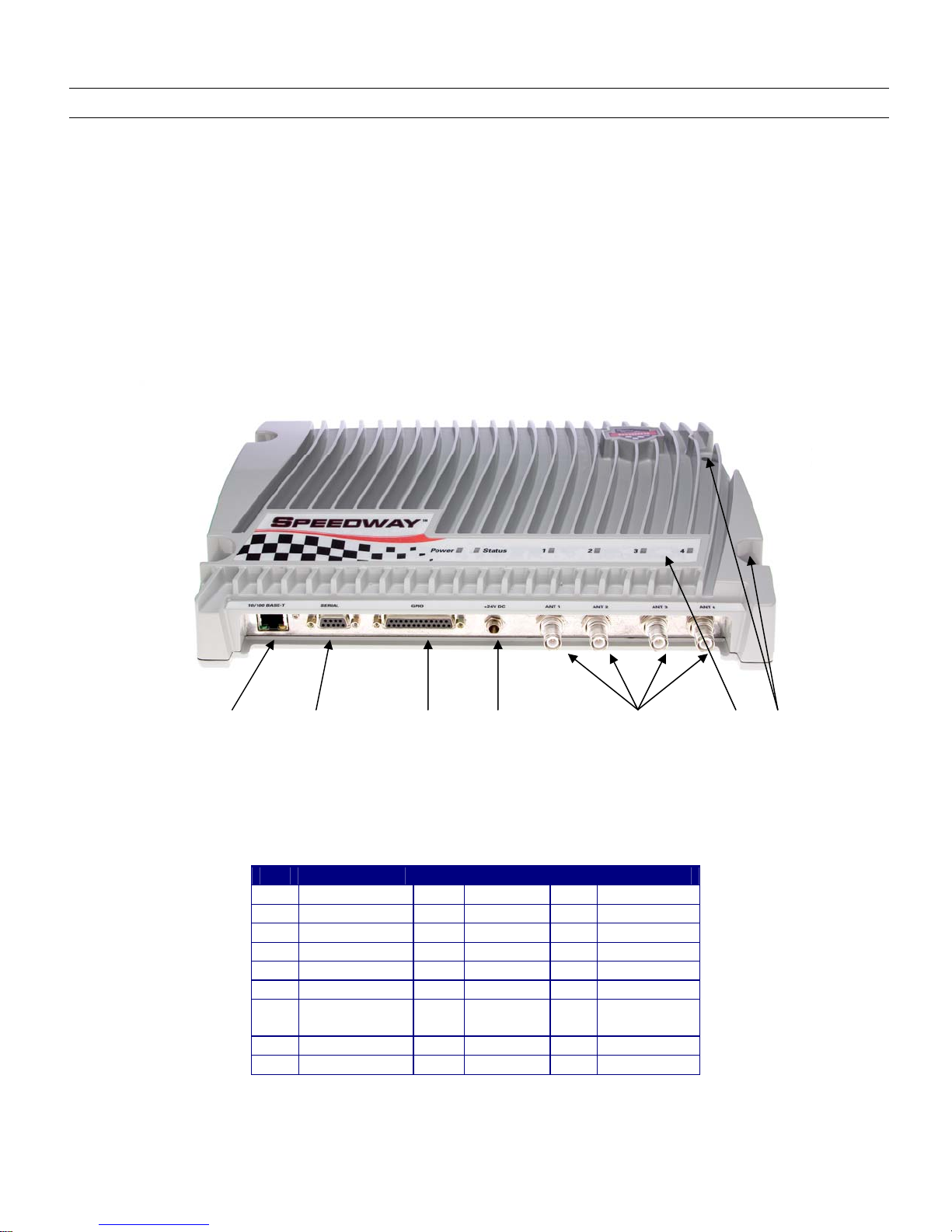
2.2. Speedway Reader I/O Ports & Status
Refer to Figure 2-1 for the Speedway reader's major ports, connectors, and status indicators, which are clearly indicated on the
unit. The Speedway reader is equipped with the following ports:
•RJ-45 Ethernet port (labeled 10/100 BASE-T)
•Four female RP-TNC RF antenna connectors (ANT1 – ANT4)
•Female DB-9 connector for serial communication (SERIAL)
•Female DB-25 connector with user I/O capability (GPIO) The GPIO contains: RS-232 serial interface, four 3.3/5V
logic inputs, and eight 3.3V logic outputs. See Table 2-2 for the pin-out, Table 2-3 for the GPIO electrical
specifications, and Figure 2-2 for the physical pin view.
Figure 2-1 Impinj Speedway Reader Port Connections
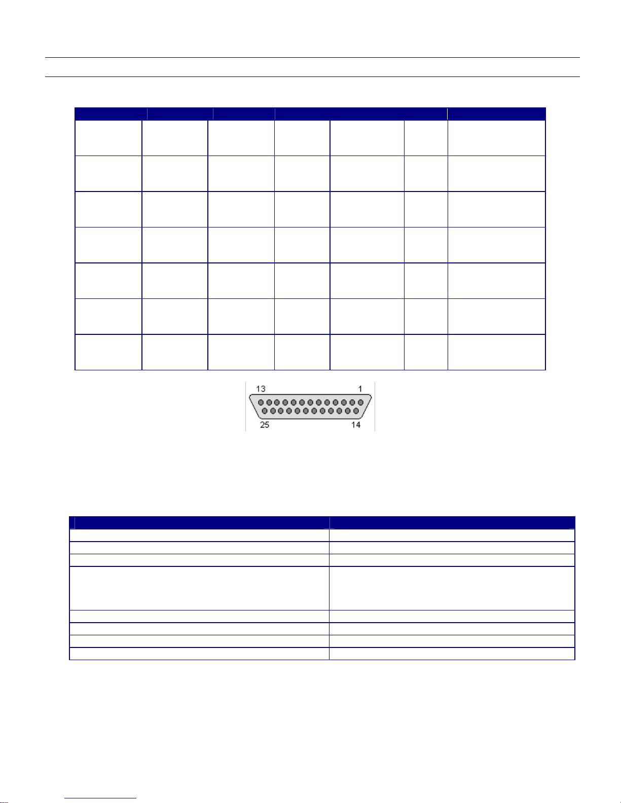
Table 2-2 DB-25 Connector Pin-Out
Pin I/O Pin I/O Pin I/O
1 No connect 10 GPIN3 19 GPOUT5
2 RS-232 RXD 11 GPIN2 20 No connect
3 RS-232 TXD 12 GPIN1 21 GPOUT6
4 RS-232 CTS 13 GPIN0 22 No connect
5 RS-232 RTS 14 GPOUT0 23 GPOUT7
6 No connect 15 GPOUT1 24 No connect
7 Signal
Ground
16 GPOUT2 25 No connect
8 No connect 17 GPOUT3
9 No connect 18 GPOUT4
Caution Pins listed in Table 1-2 as “No connect” must be left unconnected.
Mounting
Holes
RJ-45
Ethernet Jack
DB-9 Serial
Port
DB-25
GPIO Port
Power
Supply Input
RP-TNC RF Antenna
Connectors
Status
LEDs
Speedway Reader IPJ-R1000 for UHF Gen 2 RFID
9
Table 2-3 GPIO Interface Electrical Specifications
Pin Parameter Description Minimum Maximum Unit Conditions
GPIN[3:0]
VIH
HIGH-level
input
voltage
2 5 V
GPIN[3:0]
VIL
LOW-level
input
voltage
0 0.8 V
GPIN[3:0]
ILI
Input
Leakage
Current
-5 5 µA Vin=0–5V
GPIN[3:0]
VI
Input
Voltage
Range
-5 5 V No damage
GPOUT[7:0] VOH
HIGH-level
output
voltage
3 3.3 V Iout = 100 µA
GPOUT[7:0] VOL
LOW-level
output
voltage
0 0.25 V Iout = -100 µA
GPOUT[7:0] VI
Input
voltage
range
-5 5 V No damage
Figure 2-2 DB-25 Female Connector
The labeled LEDs indicate Power, Status, and antenna activity. The LEDs that correspond to the connected antenna(s)
(labeled 1, 2, 3, and 4), only light green when active (transmitting). A description of the status LED states appears in Table 2-4.
Table 2-4 LED Status Indicators
Reader Operation LED Action
Startup Continuous Red
Power-on Start Test (POST) Failure Flashing Red (~2 Hz)
Bootloader Running Off
File System Mounting Operation
(May also occur in certain upgrade scenarios to indicate the
unit is functional but in a file system operation that will take
some time to complete.)
Alternately Flashing Red/Green (1 Hz)
Speedway Reader able to Accept Mach1™ Connection Continuous Green
Speedway Reader in Active Mach1™ Connection Flashing Green (1 Hz)
Inventory in Progress with Tags in Field Flashing Orange (1 Hz)
Inventory in Progress with no Tags in Field (for 3 sec) Flashing Orange (1/3 Hz)
Note Mach1™ denotes the Speedway RFID Command Interface, used by the reader to communicate with
EPCglobal™ Generation 2 (Gen 2) RFID tags.
2.3. Mounting the Speedway Reader
When securing the unit with #10 screws via the four mounting holes, the Speedway reader may be mounted horizontally or

Speedway Reader IPJ-R1000 for UHF Gen 2 RFID
10
vertically on a stable surface where it will be safe from disturbance. Keep the unit away from direct sunlight, high humidity,
extreme temperatures, vibration, and sources of electromagnetic interference, as any combination of these conditions may
degrade performance or shorten the life of the unit.
2.4. Connecting Power
Connect the AC power plug into a suitable 100-240 VAC, 50-60 Hz power outlet. The reader’s green Power LED will light
when power is on. The reader will then begin its boot sequence (the normal boot time for the reader’s operating system is ~50
seconds). The reader will not accept commands until the boot sequence is complete.
2.5. Connecting the Antenna(s)
The Speedway reader is equipped with four (4) independent, bidirectional, full duplex TX/RX ports (monostatic).
Caution Unused antenna ports must be left unconnected; they should not be terminated.
2.5.1. FCC and Industry Canada
Warning Position reader antennas such that any personnel in the area for prolonged periods of time may safely
remain at least 25 cm from the antenna’s surface. See FCC OET Bulletin 65, “Evaluating Compliance with FCC
Guidelines for Human Exposure to Radiofrequency Electromagnetic Fields,” and FCC OET Bulletin 56, “Questions
and Answers about Biological Effects and Potential Hazards of Radiofrequency Electromagnetic Fields,” for more
details.
Warning Readers of hardware revision 2.0 (see section 2.5.1.1) and higher and running software versions 2.6.0
and higher are capable of up to 32.5 dBm conducted power on the Speedway housing RF connector
and require professional installation.
For readers of revision 1.X.X, power has been factory preset to 30 dBm to accommodate an antenna with 6 dBi composite gain
(inclusive of cabling). The Speedway reader may only be operated with Impinj-approved antennas and can radiate no more
than 36 dBm EIRP (Equivalent Isotropically Radiated Power) per FCC Part 15.247 regulations. The Speedway output power
may be increased to provide the maximum allowable EIRP subject to a maximum conducted power allowance as well. The
maximum conducted power at the antenna connector can be no more than 30 dBm. The maximum allowable output power of
the reader can be set to satisfy both the conducted and radiated maximum criteria. The expression for the maximum reader
power setting is:
Maximum power setting (in dBm)
= THE SMALLER OF
(36 – Composite Antenna Gain (in dB))
OR
(30 + Cable loss (in dB)),
where the composite antenna gain comprises the maximum linear antenna gain in dBi minus any cable loss between the reader
and antenna in dB. Approved antenna vendors, model numbers, and associated gain are listed below:
•Cushcraft Model Number S9028PCL/R (left- or right-hand CP); 6 dBi composite gain (including integrated pigtail
with RP-TNC female connector)
•Sensormatic Electronics Corp. model number IDANT20TNA25 (includes 25 foot Belden 7806A RG-58 coaxial cable
with 2.5 dB loss); 5.5 dBi composite gain
•Sensormatic Electronics Corp. model number IDANT10CNA25 (includes 25 foot Belden 7806A RG-58 coaxial cable
with 2.5 dB loss); 3.5 dBi composite gain
!
!
Speedway Reader IPJ-R1000 for UHF Gen 2 RFID
11
•Sensormatic Electronics Corp. model number IDANT10CNA06 (includes 6 foot Belden 7806A RG-58 coaxial cable
with 0.6 dB loss); 5.4 dBi composite gain
•Impinj Model Number IPJ-A0301-USA (Mini-Guardrail); -15 dBi gain
•Impinj Model Number IPJ-A0400-USA, CSL CS-777-2 (Brickyard) with 5 foot integrated pigtail to RP-TNC female
connector; 2 dBi composite gain
•Impinj Model Number IPJ-A0401-USA (Guardwall) with 6 foot integrated pigtail to RP-TNC female connector; 6 dBi
composite gain
Warning The use of any other antenna may damage the reader or adversely affect performance.
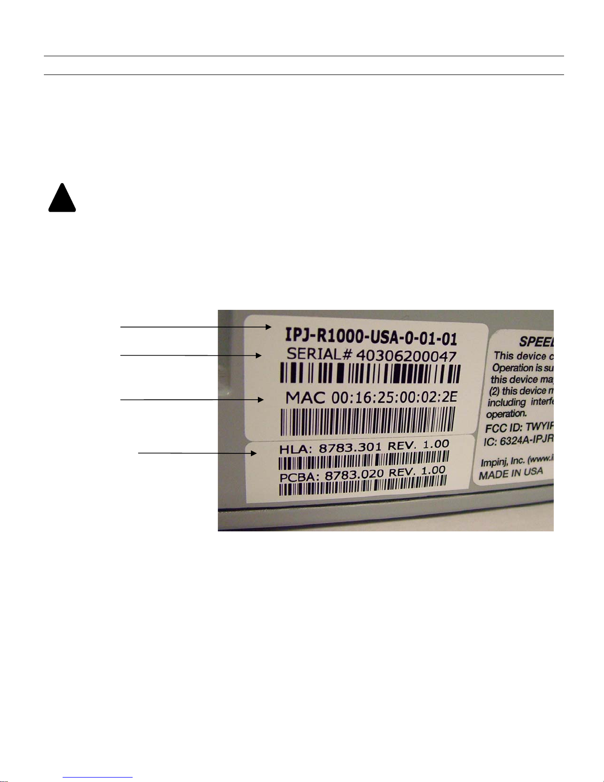
2.5.1.1. Hardware Version
Every reader has a label on the side listing the part number, the serial number, MAC address and hardware revision number
(see Figure 2-3).
Figure 2-3 Reader Labeling
2.5.2. European Economic Area
European regulations allow a maximum radiated power of 33 dBm ERP (Effective Radiated Power) for high power RFID
systems. The maximum Speedway output power is determined by the following equation:
Maximum power setting (in dBm) = 33 – Antenna Gain (in dBd) + Cable loss (in dB)
For example, for an application with an antenna gain of 6 dBd and cable loss of 2 dB, the reader output power can be set no
higher than 33-6+2 = 29 dBm. Note that it is important to apply the antenna gain expressed in dBd (dB with respect to a
dipole), which is equivalent to the isotropic antenna gain (in dBi) minus 2.15 dB. Additionally, the antenna gain used to set the
output power must be the maximum linear gain of the applicable antenna.
!
Part numbe
r
Serial numbe
r
MAC address
Hardware revision
Speedway Reader IPJ-R1000 for UHF Gen 2 RFID
12
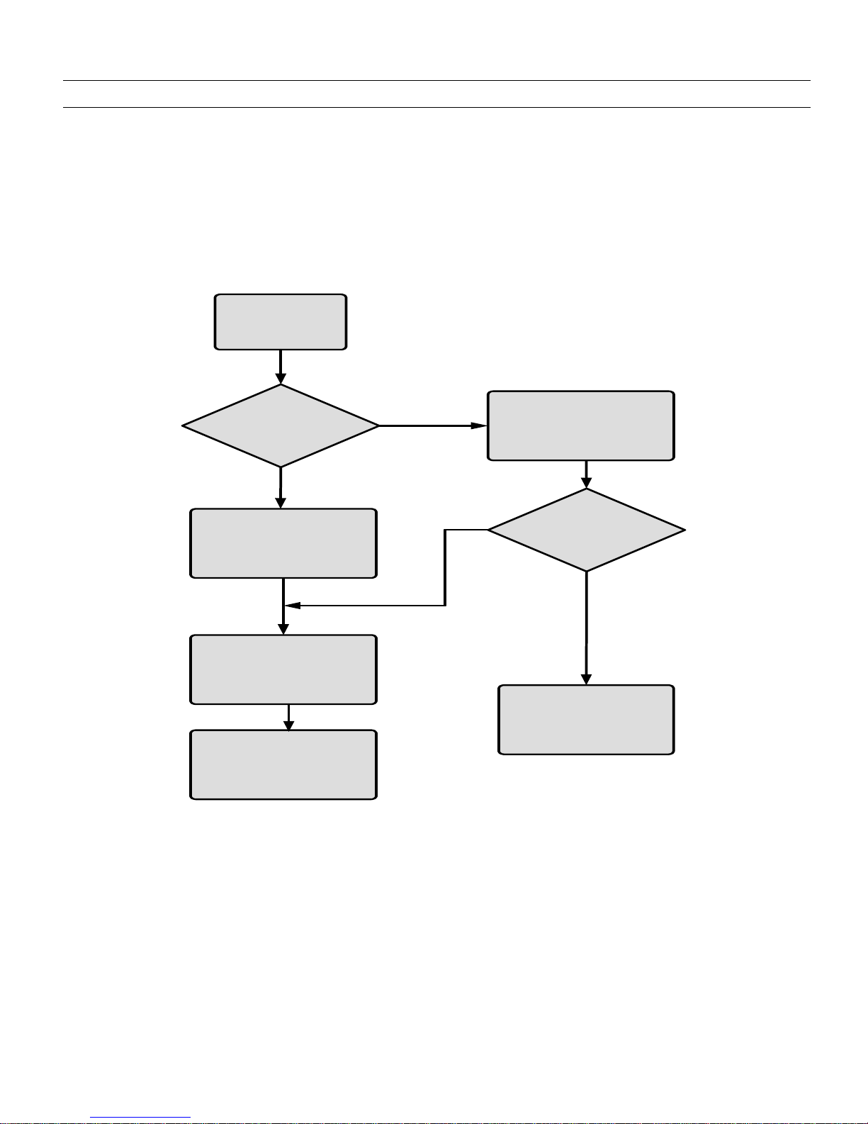
3.Communicating with the Speedway Reader
Reader connectivity and control is accomplished via either network (Ethernet, TCP/IP) or serial (RS-232) interfaces on the
Speedway unit (see Figure 3-1).
If connecting via Ethernet, see Section 3.2. If your network equipment is not compatible with the default network configuration
of the reader (DHCP), connecting via the serial interface will be necessary to establish initial command line-level
communications with the Speedway reader. If making a direct serial connection, see Section 3.1.
Configure PC to
Static IP Address
Configure Reader
IP Address
Set Up Reader
Serial Port
Yes
Yes
Look Up IP
Address of
Reader via MAC
on DHCP Server
Set Up
Network
Addressing
No
No
Connect Reader
to N etw ork
Access to
DHCP Server?
Existing DHCP
Network?
Figure 3-1 Configuration Options
Speedway Reader IPJ-R1000 for UHF Gen 2 RFID
13
3.1. Preparing Serial Connectivity
Serial communication with the reader can be used at any time in conjunction with, or in lieu of, Ethernet connectivity in order
to configure the reader. The serial interface may be necessary to establish initial communications with the Speedway reader
(via the command line interface) if your network equipment is not compatible with the default network configuration of the
reader (DHCP). In this case, the reader’s network connection can be configured using the serial port; Ethernet connectivity can
then be used for control thereafter.
Launch HyperTerminal (supplied with Microsoft Windows) or a similar communication program (such as Tera Term for
Windows or Minicom for Linux) to establish serial reader communication. Configuration settings are entered via the command
line interface (see section 4), accessed via your preferred terminal emulator, the prompt for which appears when the reader is
connected to the PC via the serial port and booted.
After connecting the Speedway reader’s serial port to the host PC’s valid/active COM port, plug the reader’s AC power unit
into a suitable 100-240 VAC, 50-60 Hz power outlet. The Power LED will illuminate when power is applied. The reader will
then begin its boot sequence. (Normal boot time for the reader’s operating system is ~50 seconds. The reader will not accept
commands until the boot sequence is complete.)
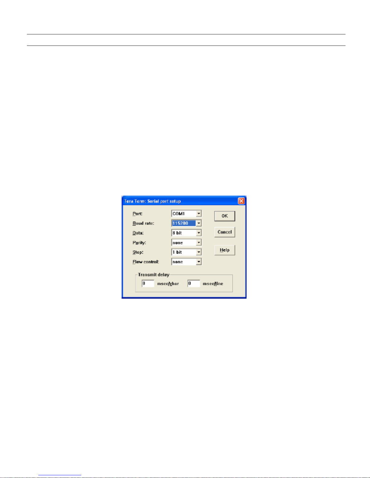
Set the communication parameters of the terminal software per Figure 3-2 (Tera Term screenshot shown).
Figure 3-2 Serial Port Configuration
Once the terminal window opens, log onto the reader by entering the established user name and password. The default login
(case-sensitive) is:
User Name: root
Password: impinj
The Speedway reader is now ready to accept command line instructions (see section 4).
Speedway Reader IPJ-R1000 for UHF Gen 2 RFID
14
3.2. Preparing Ethernet (TCP/IP) Connectivity
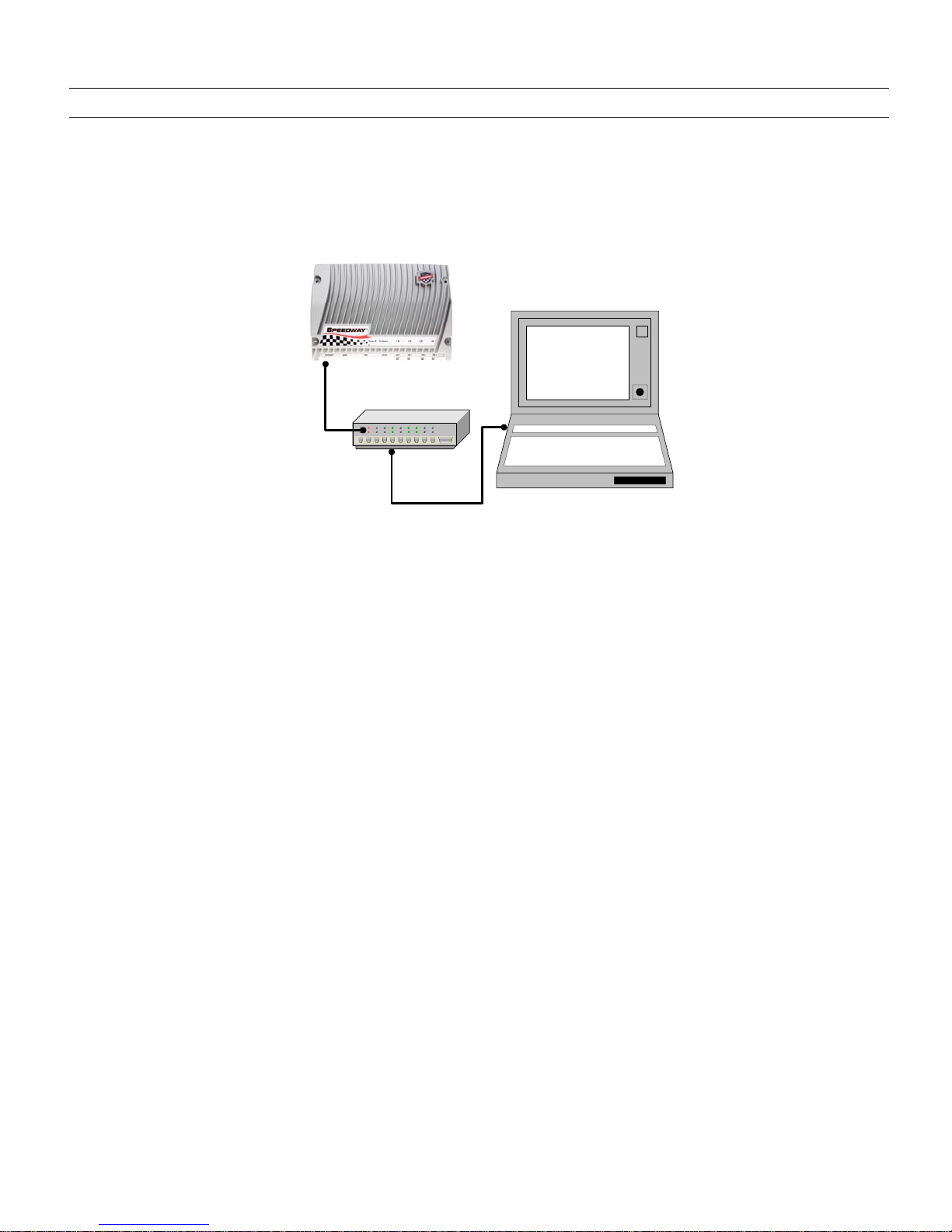
Connect the reader to your network via the Ethernet port (see Figure 3-3). If your network is capable of communicating to the
reader in its default IP configuration (DHCP), then complete and verify connectivity as described below. Note that the host
computer must be on the same subnet as the reader.
PC
Ethernet
Ethernet
Figure 3-3 Ethernet Connectivity
Connect the computer’s Ethernet port to the Speedway reader using one of the following two methods:
•Use an Ethernet router or switch with either PC IP address set to a static address within the subnet of the reader
(switch) or router’s DHCP set to provide the PC with an IP address within the reader’s subnet.
•Use a single Ethernet crossover cable to connect directly to your PC with the PC IP address set to a static value within
the subnet of the reader.
To verify correct TCP/IP connectivity ping (using the “ping” command) or traceroute (using the “traceroute” command in a
Linux environment, or the “tracert” command in a Windows environment) the reader’s IP address using the PC’s command
line interface. Once connectivity is established, open the computer’s web browser application and connect to the Speedway
reader’s hosted webpage (see Section 4), and login to complete the Speedway reader configuration. The default login (case-
sensitive) is:
User Name: root
Password: impinj
Proceed to section 4 to configure the network.
3.3. Mach1 Interface
The Speedway reader has a comprehensive RFID Command Interface, the Mach1, used by the reader to communicate with
EPCglobal™ Generation 2 (Gen 2) RFID tags. Many application providers offer software that is compatible with Mach1.
Consult your solutions provider or applications software vendor for additional information.

Speedway Reader IPJ-R1000 for UHF Gen 2 RFID
15
4.Network Configuration
The network may be configured for the Speedway reader using the Rshell command line interface (CLI), accessed via the serial
port (see section 3.1) if your system does not support DHCP.
To complete the host name, concatenate the last three bytes of the unit’s MAC address (printed on the Speedway reader
enclosure and expressed in hexadecimal, e.g., MAC 00:16:25:00:41:0C) to the word “speedway” separated by “-” (e.g.,
speedway-00-41-0C).
Shown here are the essential configuration commands; for complete information on this interface, see section 8).
To view the reader's current configuration settings, enter the following command at the prompt:
> show network summary
The reader will respond with the following (sample only; actual data will differ):
> show network summary
Status=0,'success'
ipAddressMode=dynamic
ipAddress=192.168.20.121
ipMask=255.255.255.0
gatewayAddress=192.168.20.1
broadcastAddress=192.168.20.255
hostname=speedway-00-41-0C
>
At this point, the TCP/IP configuration parameters, such as its IP status (static or dynamic) and hostname, may be changed via
the following command examples:
•To set hostname, at the prompt, enter the command:
config network hostname <HOSTNAME>
•To set static IP address, at the prompt, enter the command:
config network ip static <IP ADDRESS> <NETMASK> <GATEWAY> <BROADCAST>
•Alternatively, either of the following two versions of the config network ip static command may be used, in which
case the reader will use default values for the unspecified parameters:
config network ip static <IP ADDRESS>
config network ip static <IP ADDRESS> <GATEWAY>
•To set DHCP, at the prompt, enter the command:
config network ip dynamic
You may now continue to use the Speedway reader in serial mode or connect to the network via the Speedway reader's
Ethernet port.
Speedway Reader IPJ-R1000 for UHF Gen 2 RFID
16
5.Speedway Reader Settings
Navigate to the Speedway reader's hosted webpage. If using DHCP with DNS hostname registration enabled, connect via the
default host name by navigating the browser to http://speedway-nn-nn-nn, where nn-nn-nn represents the host name suffix.
To complete the host name entry, concatenate the last three bytes of the unit’s MAC address (printed on the Speedway reader
enclosure and expressed in hexadecimal, e.g., MAC 00:16:25:00:41:0C) to the word “speedway” separated by “-” (e.g.,
speedway-00-41-0C).
If your DHCP server does not support DNS hostname registration, the option has been turned off in Rshell, or you are using a
static IP address, navigate to the IP address assigned (e.g., http://xxx.xxx.xxx.xxx) or the host name manually specified in your
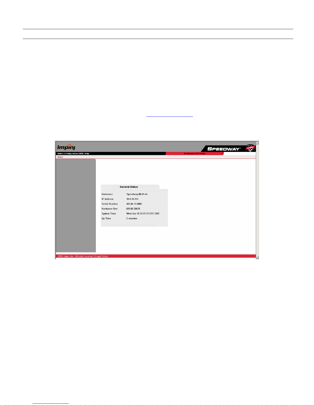
DNS server (e.g., http://hostname). You’ll then be directed to the specific Speedway unit’s homepage (see Figure 5-1), which
details the hostname, IP address, serial number, hardware revision, and system statistics information. Note that the actual GUI
appearance may vary from that shown in this User’s Guide.
Figure 5-1 Speedway Reader Homepage
The Speedway reader applet is a Java program that runs from within a web browser. The Speedway reader requires Java
Runtime Environment (JRE), version 1.4.2 or later. Note that the Windows 2000 default of JRE is 1.3.1. The latest version of
JRE can be downloaded from: http://java.com/en/download/manual.jsp
The Speedway reader applet is accessed via the RFID menu tab in the navigation bar at the top of this page. (If the applet is
opened, no other external software may connect to the reader via Mach1™.) Clicking this tab will bring up a region selection
page (see Figure 5-2).
Speedway Reader IPJ-R1000 for UHF Gen 2 RFID
17
Figure 5-2 Region Selection Page
Selecting a region will bring up a dialog box prompting the user to enter a login ID and password, the default for which is:
User name: root
Password: impinj
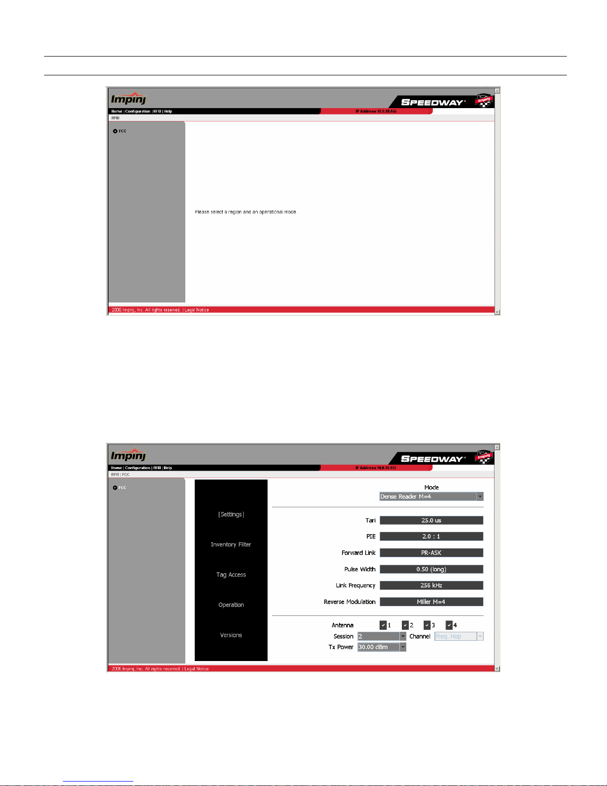
The Java applet will load and open the Settings page (see Figure 5-3).
The five user-selected fields on the Settings page include Mode, Antenna, Session, Transmit Power, and Channel, each of
which are described below.
Figure 5-3 Speedway Reader Settings Page
Mode
The reader mode is established via the Mode pull-down menu. Mode profile is a factory preset that configures the reader
according to the respective default settings of that mode. For specific usage applications of the various modes, see Table 5-1.
Speedway Reader IPJ-R1000 for UHF Gen 2 RFID
18
Table 5-1 Mode Usage
Mode Mode Description Usage
0 Maximum Throughput
Very fast read rate
Very wide spectral occupancy
Used for low interference environments where speed matters
1 Hybrid
Fast read rate
Intermediate spectral occupancy
Tolerant of some interference
2 Dense reader M=4
Intermediate read rate
Minimal spectral occupancy
Very robust to interference
3 Dense reader M=8
Half the data rate of Mode 2
Miller (M=8) may be used in extreme interference environments where tags are
stationary or moving slowly
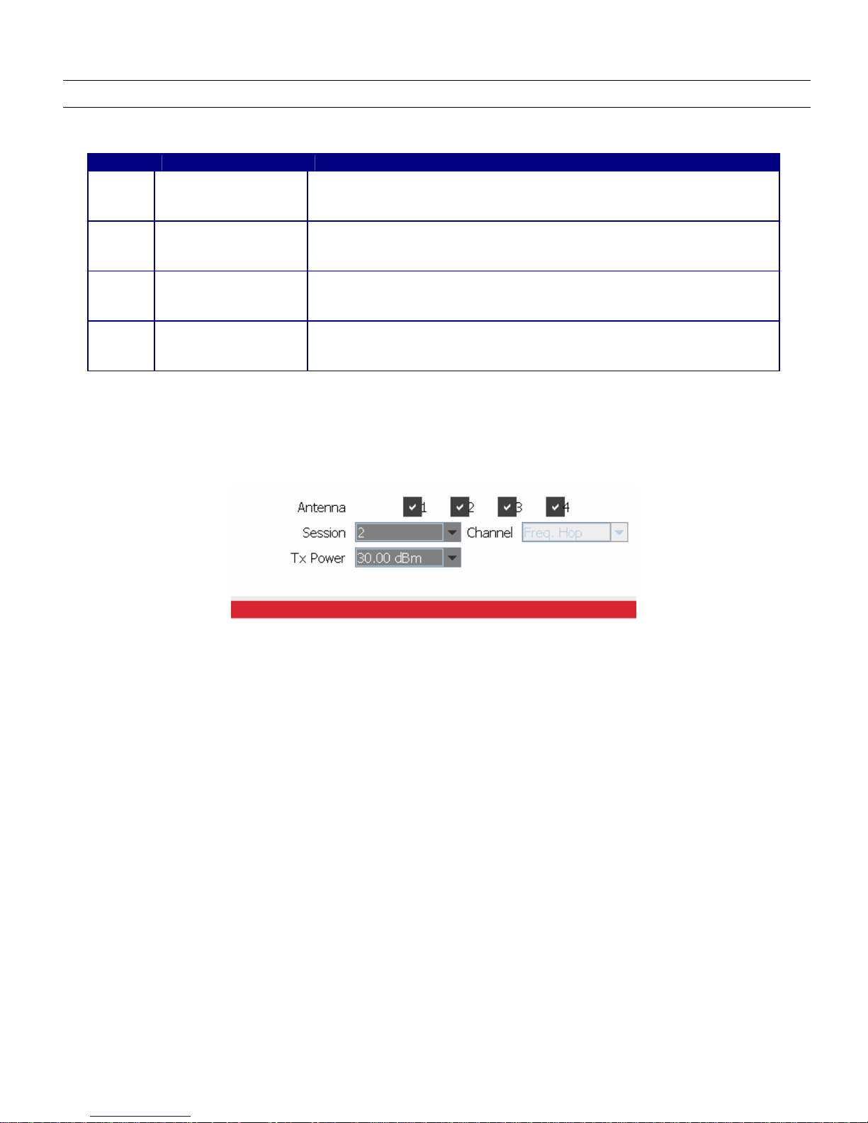
Antenna
The Speedway reader supports four (4) independent, bidirectional, full duplex TX/RX ports. Each antenna port is labeled
(ANT1−ANT4) on the Speedway unit and these designations correspond to the Antenna selection buttons that appear on the
lower third of the screen. Only those antennas activated by clicking the appropriate button(s) will be operational. (See Figure
5-4.)
Figure 5-4 Closeup of Variable Selections
Session
The reader may be assigned to one of three sessions (1−3), selectable via the Sessions pull-down menu. A function of dense-
reader mode, the use of sessions allows as many as three different readers to access the same population of tags through a time-
interleaved process. In this mode, a shelf-mounted reader in the midst of a counting operation (assigned to Session 1, for
example) may be interrupted by another reader entering the field—possibly a handheld reader—to perform its own inventory
operation (in Session 2, for example). A dock door or forklift reader (assigned to Session 3, for example) might also initiate an
inventory round. Because Gen 2 tags maintain a separate "inventoried" flag to keep track of each of these various random and
independent sessions, they're able to seamlessly resume their participation.
Transmit Power
The reader power setting is selected from the Tx Power pull-down menu. The output power ranges from 15 dBm to a
maximum of 30 dBm (in .25 dB increments), measured at the Speedway reader's antenna ports.
Channel
North America: The FCC stipulates frequency hopping across the North American spectrum allocated to UHF RFID
(902−928 MHz, with hopping occurring between 902.75−927.25 MHz in 500 KHz steps). As such, the Speedway reader does
not allow the setting of a static frequency for North American operation and the Channel is factory-set and fixed to frequency
hop.
Europe: A pulldown menu supports channel selection.
Taiwan: The NCC stipulates frequency hopping across the Taiwanese spectrum allocated to UHF RFID (922-928 MHz, with
hopping occurring between 922.25–927.75 MHz in 500 KHz steps). As such, the Speedway reader does not allow the setting of
a static frequency for North American operation and the Channel is factory-set and fixed to frequency hop.

Speedway Reader IPJ-R1000 for UHF Gen 2 RFID
19
Speedway Reader IPJ-R1000 for UHF Gen 2 RFID
20
6.Using the Speedway Reader
Once the Speedway reader settings have been established, the user may proceed directly to the Operation screen by clicking
its menu navigation button.
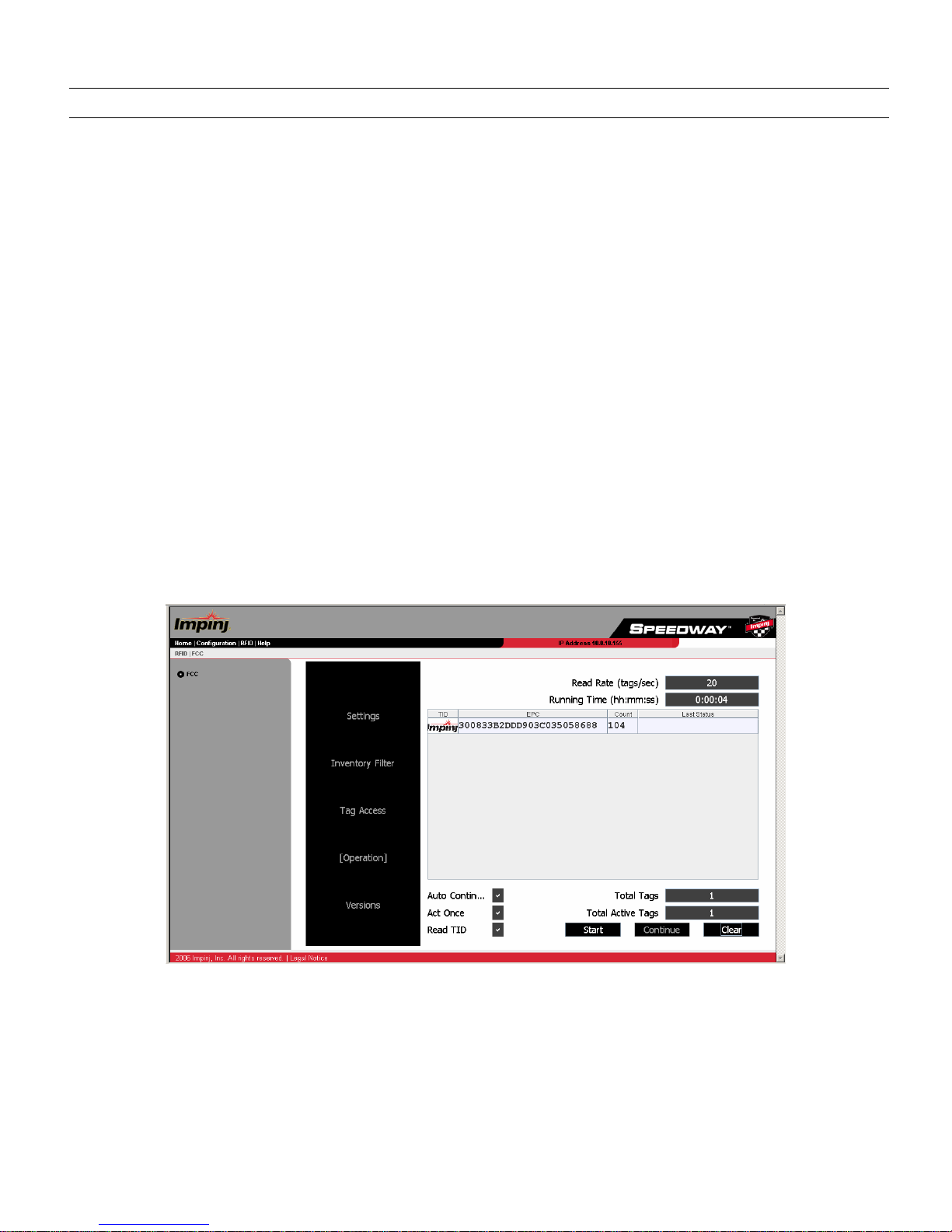
6.1. Operation Screen—Monitoring Inventory Results
From the Operation page, simply click the Start/Stop toggle button to begin reading tags within range of the reader. The Clear
button clears the results of the inventory operation that commenced with Start.
Tags being read are displayed in white fields, which fade to blue after not being seen by the reader within the last ~10 seconds.
To see all tags and their status, simply scroll the screen.
As tags are read, their EPC numbers appear in the primary window of the Operation screen. If the Read TID button on the
Operation screen has been enabled, the logo of the tag silicon manufacturer corresponding to the TID will also be displayed.
In addition to the EPC and TID, the results displayed include: Read Rate (expressed as tags/sec), Running Time (in hh:mm:ss
from last Start), Total Tags (total number of tags read), and Total Active Tags (number of tags currently in the reader's field of
view).
For more sophisticated inventory operations, the Inventory Filter and Tag Access pages allow the selection of tags according
to user-specified criteria and rules. To access the Inventory Filter, Tag Access or protocol setup menus, any currently executing
operation must be stopped.
Figure 6-1 Operation Screen
6.2. Operation Screen—Filters
If the Inventory Filter has been activated (see Section 6.3), this status will be indicated in the Operation screen view (see Figure
6-2) with the text **Inventory Filter** appearing at the top of the screen. Likewise, if the Halt Filter has been activated (see
Section 6.4), the text **Halt Filter** will appear.
Auto Continue
Other manuals for SPEEDWAY IPJ-R1000
1
Table of contents
Other impinj Card Reader manuals


