Elk ULTRAPROX ELK-106055 User manual
828-397-4200 Voice
828-397-4415 Fax
http://www.elkproducts.com
email: [email protected]
PO Box 100 • Hwy. 70W • Hildebran, NC 28637 • USA
UltraProx Weigand
Reader
ELK-106055
APPLICATION:
TheElkUltraProxWeigandReaderisacompact,
technically advanced external proximity reader
with 26 bit Weigand output for use with most
access controllers and the Elk M1 control family.
It is ideal for higher security installations and as
an alternative to remembering PIN codes.
FEATURES:
•Compatible with ELK M1 control family
•Compatible with most access controllers
•26-bit Weigand Output
•Slimline waterproof housing with epoxy potted
electronics
•User configurable inputs for the onboard buzzer
and green LED
•Compatible with Clamshell Style (Credit Card
size) Proximity Cards (ELK-M1PRC)
•Compatible with Keychain Style Proximity Fobs
(ELK-M1PRF)
•Substitutes for User Code Pin Entry
SPECIFICATIONS:
•Reader Format: 26 bit Weigand
• Nominal Read Range: ~ 3"
•Operating Voltage: 12 VDC
•Current Draw: 50 mA.
•Size: 1.9 W x 3.2" H x .9" D
Features or Specifications subject to change without notice.
03/06
ENROLLINGPROXCARDSANDFOBS
WITH M1 CONTROL
Each prox card/fob must be enrolled into a User
Code location, using the same procedures that
are used to add/change User Code PINs.
1. On the Keypad, press the center ELK key.
2. Press 6 to jump directly to Menu 06 - Change
User Codes OR Use the UP or DOWN arrow
keys to scroll to the menu.
3. Press the RIGHT arrow key to select Menu 6.
Enter a Master user code (PIN) to gain
access to this menu.
4. Use the UP or DOWN arrow keys to scroll to
the User Code location (001 to 099) where
the Prox card/fob is to be enrolled. OR enter
the three digit number, i.e., 050 for User 50.
5. Select CHG by pressing the RIGHT arrow key.
6. The keypad will display the existing 4 or 6
digit code that is programmed for this user
along with any programmed name.
7. Place a new (not previously enrolled) prox
card/fob near the UltraProx Weigand Reader.
The nominal read range is approximately 3"
from the front surface. The clam-shell type
prox cards generally have a better read range
than fobs.
8. If the keypad accepts the new prox card/fob, it
will beep 3 times and display a 12 digit code,
which is part of the ID stored in the card/fob.
If the keypad rejects the prox card/fob, it will
produce a low error tone and display:
Code Not Authorized, Redo
The reject error may be caused by:
A. The card or fob has already been enrolled
(the M1 does not allow duplicate codes)
OR
B. The facility code stored in the prox card/fob
does not match the ELK facility code. The
UltraProx Weigand Reader can only read
cards/fobs which have the matching facility
code.
9. After a prox card/fob has been enrolled into a
user code location, its capabilities are set by
the User Code Options found in Menu 02 of
the M1 Installer Level Programming. The
most common of these options are:
- Arm the M1 Control.
- Disarm the M1 Control.
- Access - Trip output to de-energize a lock **
** The activation assignment for M1 Outputs
requires the Whenever/And/Then Rules
programming of the Elk-RP Software.
The following example is a rule to activate
Output 003 for 10 seconds when a valid prox
card/fob (with Access Option enabled) is
presented at Keypad 01. The output could be
used to break or make power to a door strike.
WHENEVER Keypad 01 Access is Activated
THEN Turn On Output 003 for 10 seconds.
UltraProx Weigand
Reader
ELK-106055
InstallationInstructionsonInside
TM
CARDS AND FOBS (ordered separately)
ELK-M1PRCProxCards
•Pack of 10, White clam shell style card
•Size: 2 1/8" L x 3 3/8" H x 3/16" T
ELK-M1PRFProxFobs
•Pack of 10, Black keyring fobs
•Size: 2 1/8" L x 1 1/4" H x 1/4" T
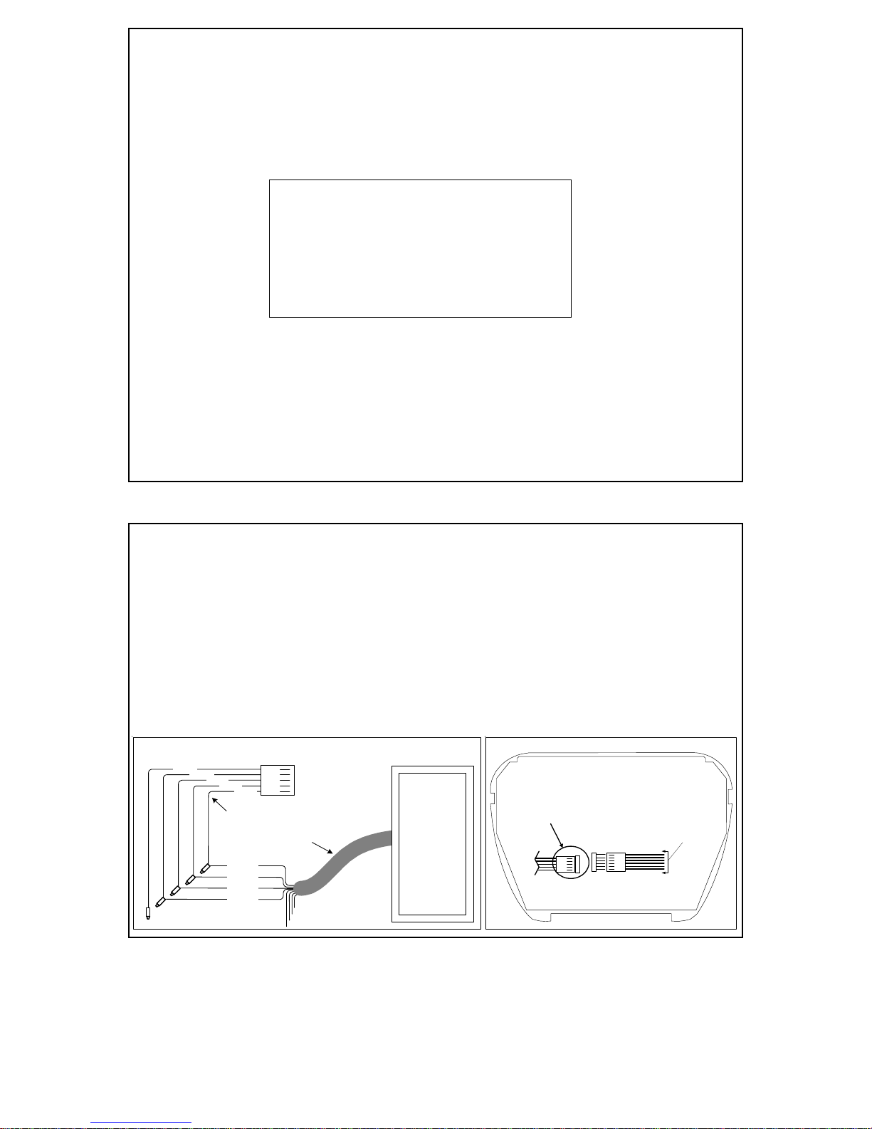
J1
J2 Connector
Back (Circuit) Side of Keypad
Six (6) conductor plug-in data bus cable
To
Proximity
Reader
Figure 2
White
Red
Black
Green
Brown Wire
Insulate (No Connection)
White Red
Black
Green
Brown
ELK-WO35A Cable Assembly
(not included) ELK-106055
UltraProx
Reader (26
bit Wiegand)
Violet
Brown
Blue
Shield }Insulate
(No Connection)
Maximum Wire
Distance = 10 ft.
Connecting an ELK-106055 Ultraprox Weigand Reader to an ELK-M1KP Keypad
(RequiresPurchaseofELK-WO35ACable)
1. Turn Off the M1 Master Power Switch.
2. Using the W035A Cable Assembly, splice wires as indicated in Figure 1.
3. Remove the M1KP Keypad from its mounting plate, disconnect the 6 pin data bus cable, and
place face down on a soft surface.
4. Locate the 5 pin male connector marked J2 (see Figure 2).
5. Plug the W035A cable into connector J2
6. Reconnect the 6 pin data bus cable to connector J1 and install the keypad onto its mounting plate.
7. Turn On the M1 Master Power Switch. Refer to the instructions for enrolling cards or fobs.
Figure 1
INSTALLATION
POWER SUPPLY
TheWeigandReader wouldnormallybesuppliedpowerfromthecontolpanelorcontrollertowhich
it is connected. Read range may be greater with a linear (non-switch mode) power supply.
ENROLLING CARDS AND FOBS
For instructions on enrolling cards and fobs, refer to the installation manual for the controller the
Weigand reader is connected to. Instructions for enrolling cards and fobs into an M1 controller can
be found on the front of this installation sheet.
Thereader is designedfor surface mountingadjacent to thedoor being controlled. Theunit is fully
sealed for indoor or outdoor use. Installation requires 2 mounting holes and a 0.3" cable hole.
WIRING
Thewiresshouldbeterminatedusingappropriate"splice"connectors(notsupplied). The piezo
beeperandthegreenLEDareinstallerconfigurable,requiriingaswitchednegativetoactivate. They
canbewiredasrequired to the controlling device.
VIOLET - Not Used
BLUE - Buzzer Control (Negative "-" Input)
BROWN - Green LED Control (Negative "-" Input)
GREEN -WeigandData 0
WHITE - Weigand Data 1
RED - Power Input +12VDC
BLACK - Power Input -12VDC Negative
SHIELD - Connected Internally to Negative
vfprox.com
117 Town Center Road
King of Prussia, PA 19406
Phone: 610.265.3380
Fax: 610.265.7830
sales@vfprox.com
Table of contents


