IMT Diamond Air DA435ELW User manual


DA435ELW: 99900917: iii
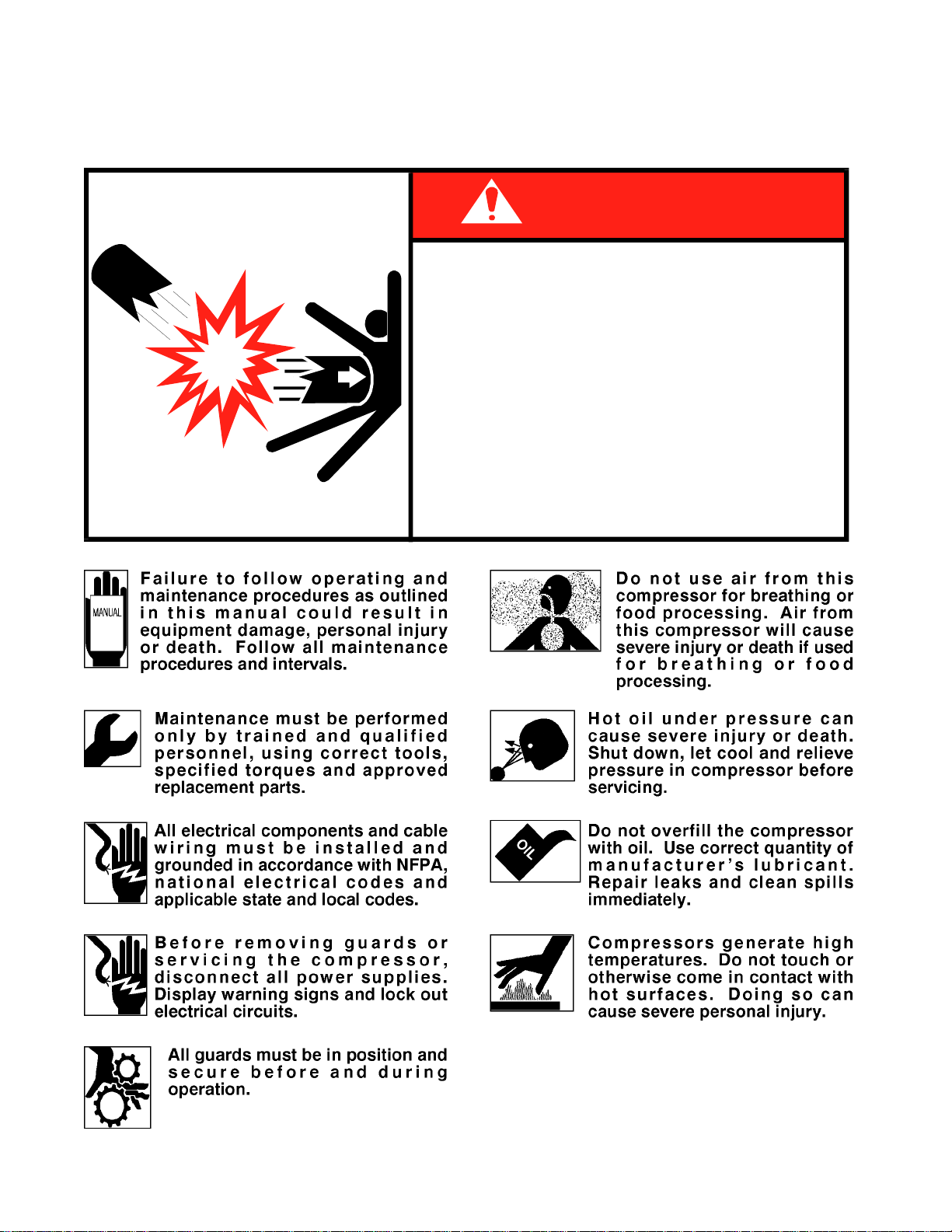
PRECAUTIONS
Read before operating your compressor!
19980223
71393886
DANGER
EXPLODINGTANK WILL CAUSE
DEATH, SERIOUS INJURY
OR PROPERTY DAMAGE
●
Drain air tank after each use to prevent
moisture build-up and corrosion which
leads to tank failure.
Assure that tank and compressor relief
valves work properly, and are at correct
pressure settings.
DO NOT modify or repair air tank.
NEVER drive vehicle with pressure in air
tank.
●
●
●


DA435ELW: 99900917: v
TABLE OF CONTENTS
PARA TITLE PAGE
Section 1. SPECIFICATIONS
GENERAL 1-1
SPECIFICATIONS 1-1
OUTSIDE DIMENSIONS 1-1
Section 2. NOT USED
Section 3. OPERATION
GENERAL 3-1
OPERATION 3-1
Section 4. MAINTENANCE & PARTS
GENERAL 4-1
ROUTINE MAINTENANCE CHECKLIST 4-1
AIR COMPRESSOR DA435ELW-PARTS (51713976) 4-2
AIR COMPRESSOR DA435ELW-DRAWING (51713976) 4-3
AIR COMPRESSOR DA435ELW-DRAWING (51713976) 4-4
REPAIR KITS 4-5
PRESSURE SWITCH KIT (51713977) 4-5
Section 5. REPAIR
5-1. GENERAL 5-1
5-2. PISTON RING REPLACEMENT 5-1
5-3. OIL PUMP REPLACEMENT 5-2
5-4. CRANKSHAFT AND BEARING REPLACEMENT 5-4
5-5. COMPRESSOR DRIVE BELT REPLACEMENT 5-5
5-6. CLUTCH REPLACEMENT 5-5
5-7. TROUBLESHOOTING 5-6
19980223


DA435ELW: 99900917: 1-119970808
SPECIFICATIONS
Bore 2-5/8"
Stroke 2-1/2"
Cylinder Configuration V4
Displacement 44 CFM*
Delivery 35 CFM*
Lubrication Oil Pump
Oil Capacity 1-1/3 qts
Cooling Water
Height 13-1/2”
Width 15”
Length 13-7/8”
Material Aluminum Alloy
Weight 87 lbs.
* @ 1400 RPM - 100 PSI
SECTION 1. SPECIFICATIONS
OUTSIDE DIMENSIONS
GENERAL
The IMT DA435ELW air compressor is a single
stage, liquid cooled, 4-cylinder, pressure lubricated
unit, with a delivery rate of 35 CFM at 1400 RPM.
The compressor is belt driven from the engine
crankshaft, through a magnetic clutch. It is engaged
and disengaged by use of an air pressure sensing,
electric switch. This pressure switch is preset at
approximately 90 PSI to engage, and 130 PSI to
disengage.
CAUTION
OPERATING THE COMPRESSOR AT 35 CFM WITH
PRESSURESGREATERTHAN130 PSIWILLSHORTEN
THE SERVICE LIFEAND VOID THE WARRANTY.
The compressor must not operate more than 6
minutes out of a 10 minute period. This will include
operating continuously for 6 minutes out of 10
minutes or operation in segments for a total of 6
minutes out of 10 minutes.


DA435ELW: 99900917: 3-119970508 SECTION 3. OPERATION
GENERAL
Each compressor is bench tested under load at the
factory to ensure proper break-in and operation.
While it is not necessary to follow any break-in
procedure, the following checks should be made
before putting the unit into service, as well as,
periodically during use.
Before start-up:
1. Check the oil level in the compressor
crankcase with the dipstick on the unit. If oil is
needed, use only IMT’s synthetic compressor oil.
2. Check the air intake filter pads on each head
to make certain that they are clean and
unobstructed. Dirty filters are a possible cause of
reduced air output. Bi-weekly checks of air
filters is recommended.
OPERATION
The system will function automatically. It will
engage the compressor clutch when the air receiver
tank pressure is below 90 psi, and disengage the
clutch when the air pressure reaches 130 psi.
CAUTION
OPERATING THIS UNIT IN EXCESS OF 1400 RPM,
WILLVOIDTHEWARRANTY,ANDWILLSHORTENTHE
NORMAL SERVICE LIFE OF THE COMPRESSOR.


DA435ELW: 4-251713976.01: 19970620
ITEM PARTNO. DESCRIPTION QTY
1. 60025012 CRANKCASE (PART OF 94) 1REF
2. 60025194 CYLINDER BLOCK 2
3. 60250270 CYLINDER HEAD 2
4. 60025193 PULSATION TANK 1
5. 70733069 REED VALVEASM 2
6. 73073030 DIPSTICK 1
7. 70014613 DIPSTICK TUBE 1
8. 60120238 OIL SCREEN TUBE (PART OF 94) 1REF
9. 60120289 OIL SCREEN (PART OF 94) 1REF
10. 72066008 OIL SCREEN CLAMP (PART OF 94) 1REF
11. 72053090 PIPE NIPPLE 1/2NPT X CLOSE 1
12. 51705310 BREATHER CAP ASM(INCL:95,96) 1
13. 72063050 WASHER 5/16 LOCK (PART OF 94) 5REF
14. 72053403 PLUG 3/8NPT SH (PART OF 94) 1REF
15. 72053413 PLUG 3/8NPT SQHD (PART OF 94) 1REF
16. 70039300 IDENTIFICATION PLATE 1
17. 72063001 WASHER 1/4 FLAT 12
18. 70014626 AIR INTAKE RETAINER 8
19. 76393803 AIR INTAKE FILTER 8
20. 72062001 NUT 5/16-18 HEX 12
21. 72060063 CAP SCR 7/16-14X1-1/4 HHGR5 4
22. 72062036 NUT 5/16-24 HEX 12
23. 76039111 GASKET 2
24. 72053403 PIPE PLUG 3/8NPT SH 6
25. 70024122 WASHER 5/16 FLAT COPPER 12
26. 72063052 WASHER 7/16 LOCK 4
27. 72063050 WASHER 5/16 LOCK 1
28. 72063001 WASHER 1/4 WRT 2
29. 72060005 CAP SCR 1/4-20X1-1/4 HHGR5 2
30. 72053404 PLUG 1/2NPT SH 1
31. 7Q072212 O-RING 8
32. 76392642 HEAD GASKET 2
33. 76392641 GASKET-CYL/VALVEPLATE 2
34. 76392119 GASKET-CYL/SPACER 2
35. 70029293 SPACER-CYL BLOCK 2
36. 60106933 CAP 2
37. 72063049 WASHER 1/4 LOCK 2
38. 72066537 CABLE CLAMP 2
39. 70394571 PLUG 2
40. 72661487 DRIVE PIN 3
41. 76393107 O-RING 2
42. 72066426 BALL (PART OF 97) 2REF
43. 70029593 INSERT (PART OF 97) 2REF
44. 7Q073017 O-RING (PART OF 97) 2REF
45. 72601708 STUD 5/16-18X3-1/2 12
53. 76392550 FOAM FILTER 4
54. 70732444 CLUTCH HARDWARE 1
55. 70056437 PULLEY-1 GROOVE .63" REF
70056304 PULLEY-2 GROOVE .50" REF
70056441 PULLEY-6 GROOVE SERPENTINE REF
70056442 PULLEY-7 GROOVE SERPENTINE REF
CONTINUED
DA435ELW AIR COMPRESSOR
(51713976-1)
ITEM PARTNO. DESCRIPTION QTY
56. 77044419 COIL 1
57. 76039119 SEAL (PART OF 91) 1REF
58. 60025007 FRT BRG HSG (PART OF 91) 1REF
59. 70055011 FRT BRG CUP (PART OF 91) 1REF
60. 70055012 FRT BRG CONE PART OF 93) 1REF
61. 60108748 CRANKSHAFT (PART OF 93) 1REF
62. 72066267 WOODRUFF KEY #6 1
63. 70055009 REAR BRG CONE (PART OF 93) 1REF
64. 60101269 OIL PUMP COLLAR (PART OF 93) 1REF
65. 72066307 DRIVE PIN (PART OF 93) 1REF
66. 70055010 REAR BRG CUP (PART OF 92) 1REF
67. 60025005 REAR BRG HSG (PART OF 92) 1REF
68. 70014583 COIL SPRING 1
69. 60101505 SLEEVE 1
70. 70051006 OIL PUMP 1
71. 60250501 PUMP COVER 1
73. 72053411 PIPE PLUG 1/8NPT SQHD 2
74. 72060731 CAP SCR 5/16-18X3/4 SH
(PART OF 94) 5REF
75. 72060731 CAP SCR 5/16-18X3/4 SH 4
76. 51029283 CONNECTING ROD 4
77. 51029285 PISTON ASM (INCL:78,79,100) 4
78. 70014627 WRIST PIN (PART OF 77) 4REF
79. 72066018 RETAINING RING (PART OF 77) 8REF
80. 70014600 OIL RING (PART OF 88) 4REF
81. 70014599 COMPRESSION RING(PART OF 88) 8REF
82. 76039092 GASKET-REAR BRG .006 2AR
76039094 GASHET-REAR BRG .010 2AR
76039144 GASKET-REAR BRG .020 2AR
76039143 GASKET-REAR BRG .015 2AR
83. 76039093 PUMP COVER GASKET 1
84. 76039112 FRT BRG HSG GASKET 2REF
87. 72060025 CAP SCR 5/16-18X1HHGR5
(PART OF 94) 5REF
88. 51014947 RING SET (INCL:80,81) 1
91. 51705709 FRT BRG HSG (INCL:57-59)
(PART OF 94) 1REF
92. 51705710 REAR BRG HSG (INCL:66,67)
(PART OF 94) 1REF
93. 51705661 CRANKSHAFT ASM(INCL:60,61,63-65)
(PART OF 94) 1REF
94. 51714001 CRANKSHAFT/CASE ASM 1
95. 60107276 CAP-MODIFIED (PART OF 12) 1REF
96. 70048080 BREATHER (PART OF 12) 1REF
97. 51714023 INSERT ASM (INCL:42-44,98,102) REF
98. 70029468 SHIM (PART OF 97) 2REF
99. 70039124 DECAL-OIL FILL 1
100. 70029062 PISTON (PART OF 77) 4REF
101. 72601060 STUD 5/16-24X2 NC GR5 12
102. 76393085 O-RING (PART OF 97) 2REF


DA435ELW: 4-551713977.01: 19971022
REPAIR KITS
GASKET KIT - 51393640
7Q072212 O-RING - CYL HEAD 8
76039092 GASKET-REAR BRG HSG .006 2
76039093 GASKET-PUMP COVER 1
76039094 GASKET-REAR BRG HSG .010 2
76039111 GASKET-CYL BLOCK BOTTOM 2
76039112 GASKET-FRT BRG HSG 2
76039119 SEAL 1
76039143 GASKET-REAR BRG HSG .015 2
76039144 GASKET-REAR BRG HSG .020 2
76392119 GASKET-CYL BLOCK 2
76392642 GASKET-REED VALVE/HEAD 2
76392641 GASKET-REEDVALVE/CLY 2
CRANKSHAFT KIT - 51705743
51705742 CRANKSHAFT ASM 1
51705661 CRANKSHAFT MACH 1REF
72066297 WOODRUFF KEY 1REF
70055010 BEARING-REAR CUP 1
70055011 BEARING-FRT CUP 1
70055012 BEARING-FRT CONE 1REF
70055009 BEARING-REAR CONE 1REF
72066307 DRIVE PIN 1REF
60101269 OIL PUMP COLLAR 1REF
PISTON RING SET - 51014947
70014599 COMPRESSION RING 8
70014600 OIL RING 4
ITEM PARTNO. DESCRIPTION QTY
1. 77041532 PRESSURE SWITCH 1
2. 72532952 BRASS INSERT 4
3. 89034176 AIR LINE 1/4" (10 FT) 1
4. 72531827 REDUCER BUSHING 3/8-1/2NPT 2
5. 72531042 ELBOW 1/8-1/4NPT 90° 3
PRESSURE SWITCH KIT (51713977)


DA435ELW: 99900917: 5-1
SECTION 5. REPAIR
19970313
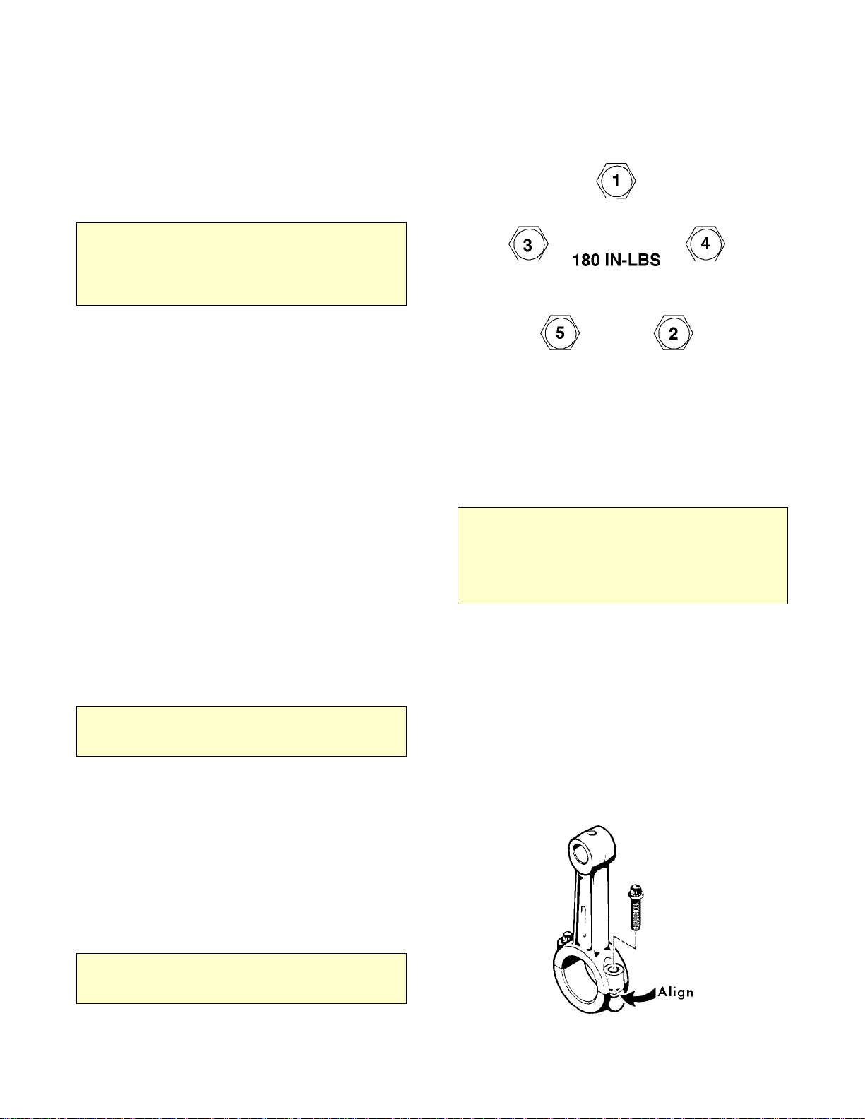
FIGURE E-2. CYLINDER HEAD TORQUE
SEQUENCE
FIGURE E-1. PISTON RING
ORIENTATION
5-1. GENERAL
This section describes the disassembly and assembly
procedures for the air compressor. In all cases,
remove the compressor from the welder before
proceeding with disassembly. Refer to the parts
drawing in section 4 of this manual for parts
locations.
5-2. PISTON RING REPLACEMENT
1. Remove the pulsation tank.
2. Unscrew the head bolts and remove the heads.
NOTE
A RUBBER FACED MALLET WILL HELP WHEN
REMOVING THE HEAD. TAP THE SIDES OF THE
HEAD CAREFULLY UNTIL THE HEAD IS LOOSE.
LIFT OFF THE HEADS.
3. Remove the cylinder bolts. Tap the sides of the
cylinder several times to break it loose from the
gasket. Rock the cylinder back and forth and lift
until it is free. Lift it off the pistons.
4. Use a single edged razor blade, or sharp putty
knife, to remove the old gasket material.
CAUTION
DO NOTALLOW THE GASKET MATERIAL TO FALL
INTO THE CRANKCASE. DO NOT NICK THE HEAD,
CYLINDER, OR CRANKCASE MATING FACES
WHILE REMOVING THE OLD GASKET. REMOVE
ALL OF THE OLD GASKET MATERIAL TO PROVIDE
A SMOOTH, CLEAN SURFACE FOR THE NEW
GASKET. FAILURE TO FOLLOW THIS PROCEDURE
MAY RESULT IN THE NEED TO RESEAL THE UNIT
LATER.
5. Hone the cylinder to break the glaze and to
remove the buildup at the top of the cylinders.
6. Measure the inside diameter of the cylinder for
roundness and excessive wear. The bore should be
2.625" (0.0025" tolerance). If the bore is oversized,
the cylinder must be replaced.
7. With a ring expander, remove the compression
and oil rings.
8. With the ring expander, install the new ring kit.
Make certain that the oil ring is on the bottom and
the beveled inside edge of the compression ring is
toward the top of the piston.
9. Position the cylinder base gasket on the crankcase.
Use a few drops of oil to hold it in position. Install
the cylinder block spacer and gasket on the
crankcase.
10. Rotate the rings so that the gaps of the three
rings are 120° apart. Lightly lubricate the inside of
the cylinder. Rotate the crankshaft so that a piston is
at the top of the stroke. Compress the rings with a
ring compressor, and slide the cylinder over the
piston. Repeat for the other piston.
CAUTION
DO NOT LUBRICATE THE RINGS. USE A LIGHT
LUBRICANT, SUCH AS WD-40 ONLY, ON THE
CYLINDER WALLS. OILING THE RINGS WILL
PREVENT THEM FROM SEATING AND CAUSE
EXCESSIVE OIL CONSUMPTION.

DA435ELW: 99900917: 5-219970508
11. Slide the cylinder down until it mates with the
crankcase. Start all cylinder mounting bolts, until
they are snug. Torque the bolts to 180 in-lbs in the
sequence shown. Do not torque to the full 180 in-
lbs all at once. Torque in 25-50 in-lb increments.
NOTE
NO GASKET SEALER IS TO BE USED ON IMT REED
VALVE COMPRESSOR GASKETS.
12. Position the gaskets and valve plate on top of the
cylinder. Position the head on thecylinder and turn
studs finger tight.
NOTE
INSTALL THE REED VALVE PLATE WITH THE IMT
LOGO UP AND WORD “EXHAUST” TOWARD THE
PULSATION TANK.
NOTE
TO THIS POINT, STUDS SHOULD STILL BE FINGER
TIGHTAND NUTS INSTALLED ON STUDS.
13. Push the heads up toward each other and tighten
center two nuts on each head to 140 in-lbs (12 ft-
lbs).
14. Torque the remaining nuts to 140 in-lbs (15 ft-
lbs) per Figure E-2.
15. Install new O rings between heads and
pulsation tank.
16. Set pulsation tank into place and finger tighten
bolts.
17. Cross tighten the pulsation tank to 180 in-lbs (15
ft-lbs).
18. Torque per Figure E-2, all head nuts to 240 in-
lbs (15 ft-lbs) plus or minus 10 in-lbs, in 25-40 lb
increments.
19. Re-torque after 15 or 20 minutes have passed,
per Figure E-2, all head nuts to rating above.
NOTE
YOU MUST DOUBLE CHECK THE TORQUE OF
EVERY NUTAND BOLT.
20. Install the compressor, connect the wiring and
the air lines.
21. Be sure all tools, welder parts, or anything else
loose are removed from compressor before startup.
Follow startup procedures listed in owners manual.
Test the unit.
CAUTION
REMOVE FINGERS FROM FAN AREA.
22. After 10 hours of operation, wait for unit to
cool and re-torque all head bolts to
recommended torque shown in Figure E-2.
NOTE
IF PRESSURE FAILS TO BUILD AND THE
COMPRESSOR IS EXCESSIVELY NOISY, CHECK
THE VALVE PLATE. IT MAY HAVE BEEN INSTALLED
UPSIDE DOWN.
5-3. OIL PUMP REPLACEMENT
1. Remove the existing oil pump cover by
removing four 5/16" machine head cap screws. A
spring behind the oil pump will push the pump
partially out as these screws are loosened.
NOTE
BE CERTAIN TO NOTE THE LOCATION OF THE OIL
PORT HOLE IN BOTH THE GASKET AND THE
COVER. IT IS IMPORTANT THEYARE ALIGNED
WITH THE PORT ON THE CRANKCASE (BOTTOM)
FOR RE-ASSEMBLY.
2. With a single edged razor blade, or sharp putty
knife, remove the old gasket material. Take care
not to damage the machined surfaces.
3. Remove the oil pump so you are able to see
inside the rear bearing housing to locate the drive
pin. The drive pin should be protruding from the
drive collar approximately 1/8".
NOTE
THE NOTCH IN THE OUTSIDE (ROTOR) OF THE
PUMP MUST FIT AROUND THIS PIN DURING
ASSEMBLY. IF NOT, THE PIN AND/OR PUMP WILL
BE DAMAGED WHEN THE CAP SCREWSARE
TIGHTENED.
4. Using a marker, mark the location of the pin on
outside of bearing housing. Doing so will assist in
alignment of parts at re-assembly. Make certain the
crankshaft is not turned after this step.

DA435ELW: 99900917: 5-319970508
Re-assemble as follows:
5. To hold the parts in alignment at assembly,
screw two 5/16" studs into two diagonal holes in the
rear of the bearing housing. Slide the gasket into
position, making certain the oil port hole is on the
bottom.
6. Hold the pump cover in the vertical position
with flat side on top, behind the compressor.
7. Locate the step machined at the front of the oil
pump port plate. The pump cover has 2 stop pins and
a third pin to prevent incorrect installation. Position
these three pins into the machined area.
8. While keeping the port plate in place against the
cover, rotate the outside (rotor) of pump to align the
notch with the mark for the drive pin, which was
applied previously.
9. Slide the pump into the housing and the cover
onto the studs up against the pump. Pressure from
the spring behind the pump will be noticed.
10. Using even pressure on the cover, attempt to
push the cover to make contact with bearing
housing. This process may require several attempts
with minor adjustments to align all parts.
13. Once it is possible to make contact with the
bearing housing, using hand pressure only, and there
remains spring pressure in return, hold the cover
tight against the bearing housing using one hand,
and screw in two cap screws using the other hand.
14. Do not tighten these two screws until after
removing the studs and inserting the other two cap
screws.
15. Tighten the cap screws in a criss-cross pattern
and torque to 180 in-lbs.
16. Install the air compressor in the welder. Connect
the air lines and wiring.
CAUTION
DO NOT RUN COMPRESSOR UNTIL CERTAIN
THERE IS OIL PRESSURE. DOING SO WILL
SERIOUSLY DAMAGE THE COMPRESSOR
17. Check for oil pressure by removing the 1/4" pipe
plug on the side of the pump cover. Very briefly,
start the compressor and stop immediately. If oil
does not squirt out of this hole in 1 or 2 quick tries,
the oil pump may be pinched or misaligned. If so,
repeat steps 1-9. If oil pressure is present, replace the
pipe plug as the compressor is ready to be run.
Check the compressor oil pressure gauge located on
the welder’s lower control panel. It should move
from zero to approximately 50 psi on initial start-up.
MACHINED STEP LOCATION STOP LOCATIONS
DA435ELW: 99900917: 5-4
5-4. CRANKSHAFT AND BEARING
REPLACEMENT
If it is necessary to replace the crankshaft, related
components must also be replaced. Replace both
bearings, both races, the key, pump collar and pump
drive pin.
NOTE
DEPENDING ON THE CONDITION OF THE
CRANKSHAFT, BEARING MAY BE REPLACED
WITHOUT REPLACING THE CRANKSHAFT.
REPLACE THE BEARING RACES WHENEVER THE
BEARINGS ARE REPLACED.
1. Remove the pulsation tank, both heads,
cylinders, and pistons. Refer to the instructions in
section 5, paragraph 2.
2. Remove the bolts on the connecting rods, and
lift them out. Reassemble the connecting rods to be
certain that the matched parts remain together on the
same crankshaft journals.
3. Remove the pump cover, oil pump, sleeve,
spring, and rear bearing housing.
4. Remove the clutch and pulley assembly, and the
front bearing housing.
5. Pull the crankshaft from he crankcase.
6. Remove all gasket material with a single edged
razor blade, or sharp putty knife.
CAUTION
DO NOT GOUGE THE MACHINED SURFACES
WHEN REMOVING THE GASKETS. THIS MAY
CAUSE LEAKS.
7. Press the bearing races out of the bearing
housing.
8. Press the tapered roller bearings off of the
crankshaft if only the bearings are being replaced. If
the crankshaft is to be replaced, discard the entire
assembly.
9. Press the new bearings into position.
NOTE
THE CRANKSHAFT SHOULD HAVE NEW
BEARINGS INSTALLED. IF NOT, PRESS THE NEW
BEARINGS INTO POSITION ON THE CRANKSHAFT.
19970429 10. Generously oil the front bearing race and install
the front bearing housing with gasket. Torque the
bolts to 180 in-lbs. Torque the bolts as shown in the
pattern below.
FIGURE E-3. BEARING HOUSING
TORQUE SEQUENCE
FIGURE E-4. ROD ALIGNMENT
11. Slide the crankshaft into the crankcase.
Generously lubricate the bearing race and install the
rear bearing housing and gaskets.
NOTE
GASKET KITS ARE SUPPLIED WITH TWO (2) EACH
OF .006, .010, .015, AND .020 GASKETS. USE
THESE REAR BEARING GASKETS IN ANY
COMBINATION AND QUANTITY TO LIMIT ALL PLAY
FRONT TO REAR, BUT STILL ALLOW THE
CRANKSHAFT TO TURN FREELY.
12. Install the oil pump as indicated in Section 5-3.
13. Install the connecting rods. Thoroughly oil the
crankshaft and rods before installing them. When
installing the rods, make certain that the tabs are
aligned on the same side of the rod as shown below.
14. Install the pistons, rings, heads and pulsation
tank.
Table of contents
Other IMT Air Compressor manuals


Popular Air Compressor manuals by other brands

Behringer
Behringer Multicom Pro MDX4400 user manual

Briggs & Stratton
Briggs & Stratton 74000 Operator's manual

CVS
CVS RKL 160 Mounting instructions

Full Boar
Full Boar V-TWIN FBACVT-5030U Original instructions

Air Techniques
Air Techniques AERO100 operating instructions

Craftsman
Craftsman evolv 921.167500 Operator's manual


ABAC
ABAC Air Compressor Instructions for use manual

Mars Air Systems
Mars Air Systems L-2254 Installation and operation

Neilsen
Neilsen CT1619 Original instructions

KUSSMAUL
KUSSMAUL AUTO-PUMP 091-9B-4-AD instruction manual

Quincy Compressor
Quincy Compressor Industrial Series instruction manual

Atlas Copco
Atlas Copco G 18 Instruction book