IMT CAS2545 Instruction Manual

Printed on 19 February, 2007
Manual Part No. 99904145
IMT CAS2545 Air Compressor
Operation, Maintenance and Spare Parts
Revised 20070220
IOWA MOLD TOOLING CO., INC.
PO Box 189
Garner, IA 50438
Tel: 641-923-3711 FAX: 641-923-2424
Website: http://www.imt.com
Copyright © 2007 Iowa Mold Tooling Co., Inc.
All rights reserved
No part of this publication may be reproduced, stored in a retrieval system, or transmitted in any
form or by any means, electronic, mechanical, photocopying, recording or otherwise without the
prior written permission of Iowa Mold Tooling Co., Inc.
Iowa Mold Tooling Co., Inc. is an Oshkosh Truck Corporation Company.


i
Contents
Revisions .................................................................................................................................................... iii
Compressor Introduction 5
Compressor Safety........................................................................................................................................7
Safety Decals.....................................................................................................................................8
Warning & Caution Decals................................................................................................................9
Instruction Decals............................................................................................................................10
CAS2545 System Description & Specifications.........................................................................................11
CAS2545 Performance Data.......................................................................................................................12
CAS2545 Performance Charts....................................................................................................................13
CAS2545 Component Identification...........................................................................................................16
Installation 17
Compressor Installation Notes....................................................................................................................17
Compressor Installation (99904153)...........................................................................................................18
Compressor Installation, Telescopic Top (99904166) ................................................................................19
Electrical Installation ..................................................................................................................................21
Electrical Installation (Non-IMT Application) (77441157) (Effective 3-15-05) ........................................22
Cooler Installation (99903573)...................................................................................................................23
Decal Installation (99904154).....................................................................................................................26
Compressor Mounting Locations (99903712) ............................................................................................28
Operation 29
Compressor Terminology ...........................................................................................................................29
Description of Components ........................................................................................................................30
Compressor Operation Test ........................................................................................................................33
Compressor Start-Up & Shut-Down...........................................................................................................33
Sub-Zero Temperature Operating Instructions ...........................................................................................35
Maintenance & Repair 37
Maintenance Schedule ................................................................................................................................38
CAS2545 Maintenance Procedures ............................................................................................................39
Lubricant Recommendations ......................................................................................................................45
Relay Module..............................................................................................................................................46
Flash Recovery Procedure ..........................................................................................................................47
Compressor Troubleshooting......................................................................................................................49
Parts 53
Parts Ordering Information.........................................................................................................................53
CAS2545 Recommended Spare Parts List..................................................................................................53
Compressor Assembly (99904093).............................................................................................................54
99904093-2 Drawing.......................................................................................................................54

ii Contents
99904093-3 Drawing.......................................................................................................................56
99904093-4 Drawing.......................................................................................................................57
99904093-5 Drawing.......................................................................................................................59
99904093-6 Drawing.......................................................................................................................61
99904093-7 Drawing.......................................................................................................................63
99904093 Complete Parts List ........................................................................................................64
Oil Separator Block Spare Parts .................................................................................................................67
Compressor Spare Parts..............................................................................................................................68
Electrical Schematic (77441156)................................................................................................................69
Hydraulic Schematic (99904155) ...............................................................................................................70

Contents iii
Revisions
DATE LOCATION DESCRIPTION
20070115 99904166,
99903712
ECN 10334 - ADDED TELE TOP INSTALLATION INSTRUCTIONS
99904093 ADDED PART NUMBERS PER PAGE
20070220 99904093,
99904148,
99904154
ECN 10382 - UPDATE AFTER PILOT BUILD


5
This volume provides information on the installation, operation, and repair of IMT hydraulic air
compressors. In addition to reading the manual, it is your responsibility to become familiar with
government regulations, hazards, and the specific operation of your equipment. Use caution
and common sense while operating and maintaining the equipment and follow all safety
procedures and regulations. Treat this equipment with respect and service it regularly.
MODIFICATIONS
Modifications to your equipment must be performed with IMT approved accessories, parts and
optional equipment. If in doubt about the safety, compatibility, or appropriateness of any
modifications, contact IMT prior to making those modifications. DO NOT alter or modify any
safety device! All safety devices must be inspected, tested and maintained in proper working
condition.
Note that decals regarding safety and operation are considered safety equipment. They must be
maintained just as any other safety device. Decals must be kept clean and legible to the
operator, operational personnel, and bystanders as specified in the decal section of this manual.
DO NOT remove, disable, or disregard any safety device attached to your equipment.
The equipment owner and/or designated employee is responsible for informing all operators,
maintenance personnel, and others involved in equipment operation about the safe operation
and maintenance of the equipment. If questions arise concerning safe operation, contact IMT or
your IMT distributor for clarification.
WARRANTY
Warranty of this unit will be void on any part of the unit subjected to misuse due to overloading,
abuse, lack of maintenance and unauthorized modifications. No warranty - verbal, written or
implied - other than the official, published IMT new machinery and equipment warranty will be
valid with this unit.
NOTICE TO THE OWNER / USER
If your equipment is involved in a property damage accident, contact your IMT distributor
immediately and provide them with the details of the accident and the serial number of the
equipment. If an accident involves personal injury, immediately notify your distributor and IMT
Technical Support at:
IOWA MOLD TOOLING CO., INC.
500 HWY 18 WEST
GARNER, IA 50438
641 - 923 - 3711
SECTION 1
Compressor Introduction

6 IMT CAS2545 Air Compressor Manual Part No. 99904145
WARNING
READ YOUR MANUAL!! FAILURE TO READ, UNDERSTAND AND FOLLOW ANY SAFETY
PROCEDURES APPLICABLE TO YOUR EQUIPMENT MAY RESULT IN EQUIPMENT
DAMAGE, SERIOUS INJURY, OR DEATH.
Three means are used throughout this manual to gain the attention of personnel. They are
NOTEs, CAUTIONs and WARNINGs and are defined as follows:
NOTE
A NOTE is used to either convey additional information or to provide further emphasis for a
previous point.
CAUTION
A CAUTION is used when there is the very strong possibility of damage to the equipment or
premature equipment failure.
WARNING
A WARNING is used when there is the potential for personal injury or death.
Treat this equipment with respect and service it regularly for a safer working environment and
longer equipment life.

Section 1 Compressor Introduction 7
Compressor Safety
AIR COMPRESSOR SAFETY PRECAUTIONS
Safety is basically common sense. While there are standard safety rules, each situation has its
own peculiarities that cannot always be covered by rules. Through experience and common
sense, you are in the best position to ensure your safety. Lack of attention to safety can result in
accidents, personal injury, reduction of efficiency and worst of all, loss of life. Watch for safety
hazards. Correct them promptly. Use the following safety precautions as a general guide to safe
operation:
WARNING
All units are shipped with a detailed Operators and Parts Manual. This Manual contains vital
information for the safe use and effective operation of this unit. Carefully read the Operators
Manual before starting the unit. Failure to adhere to the instructions could result in SERIOUS
BODILY INJURY or PROPERTY DAMAGE.
Make sure all protective covers and guards are in place, and that the canopy / doors are
closed during operation.
Be very cautious in using this machine in flammable gas risk areas. Use in these areas may
require additional safety equipment such as gas detectors, exhaust spark arrestors and shut-
off valves, depending on local regulations of the level of risk involved.
Relieve pressure from the entire system before attempting to service the compressor or
removing any compressor parts.
Do not attempt to service any part while machine is operating.
Ensure adequate ventilation when releasing discharge air into a confined space.
WARNING
Check the compressor sump oil level only when the compressor is not operating and system
is completely relieved of pressure. Open service valve to ensure relief of system air pressure
when performing maintenance on compressor air/oil system.
FAILURE TO COMPLY WITH THIS WARNING MAY CAUSE DAMAGE TO PROPERTY AND
SERIOUS BODILY HARM.
Do not operate the compressor at pressure or speed in excess of its rating as indicated in
“Compressor Specifications”.
Periodically check all safety devices for proper operation.
Do not play with compressed air. Pressurized air can cause serious injury. Avoid bodily
contact with compressed air.

8 IMT CAS2545 Air Compressor Manual Part No. 99904145
Exercise cleanliness during maintenance and when making repairs. Keep dirt away from
parts by covering parts and exposed openings.
DANGER
Do NOT use IMT compressor systems to provide breathing air. Such usage, whether
supplied immediately from the compressor source, or supplied to breathing tanks for
subsequent use, can cause serious bodily injury. Air discharged from the compressor may
contain carbon monoxide or other contaminants.
IMT disclaims any and all liabilities for damage or loss due to personal injuries, including
death, and/or property damage including consequential damages from using any IMT
compressors for breathing air.
Do not disconnect or bypass safety circuit system.
Do not install safety devices other than authorized IMT replacement devices.
Close all openings and replace all covers and guards before operating compressor unit.
Do not leave tools, rags, or loose parts on the compressor or drive parts.
Do not use flammable solvents for cleaning parts.
Keep combustibles out of and away from the compressor and any associated enclosures.
Use hearing protection around the compressor. The compressor produces loud noises
which, over extended exposure, can cause hearing loss.
The owner, lessor, or operator of the compressor are hereby notified and forewarned that any
failure to observe these safety precautions may result in damage or injury.
IMT expressly disclaims responsibility or liability for any injury or damage caused by failure to
observe these specified precautions or by failure to exercise that ordinary caution and due care
required when operating or handling the compressor, even though not expressly specified
above.
Safety Decals
A compliment of warning decals are supplied with each unit. These decals must be affixed to the
unit after it has been painted, trimmed, and undercoated, etc. and prior to being put into service.
The decal placement should ensure decals are clearly visible to the user and service personnel.
All decals for the IMT CAS2545 Air Compressor can be ordered on a decal sheet, part number
95720760.

Section 1 Compressor Introduction 9
Warning & Caution Decals
WARNING
Do not operate with
cover removed.

10 IMT CAS2545 Air Compressor Manual Part No. 99904145
Instruction Decals
AIR
ENABLE
FAN
HYD SOL
HI-TEMP
POWER
HIGH TEMP / RESET
8500 RPM MAX
LIFT HOOK
COMP. OIL TEMP
TANK
PRESSURE
AIR FILTER
SERVICE
INDICATOR
OIL
DRAIN
FILL OIL BETWEEN
MINIMUM AND
MAXIMUM LEVELS.
USE IMT ROTARY SCREW
COMPRESSOR FLUID ONLY.
1. CHECK FLUID LEVEL COLD WITH
TRUCK OFF AND PARKED ON LEVEL
GROUND.
2. FLUID LEVEL MUST BE MAINTAINED
BETWEEN MINIMUM AND MAXIMUM
AS INDICATED IN FIGURE.
3. CHECK OIL LEVEL BEFORE
STARTING COMPRESSOR.
4. CHECK OIL LEVEL AFTER EVERY
100 HOURS OF OPERATION. REFER TO
MANUAL FOR PROCEDURE.
OIL FILL
MAX
MIN
In addition to these instruction decals, the CAS2545 air compressor is marked with a serial
number tag at the bottom of the back of the unit.

Section 1 Compressor Introduction 11
CAS2545 System Description & Specifications
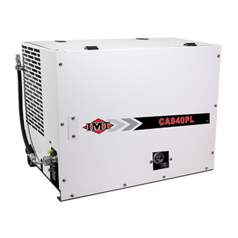
The IMT CAS2545 air compressor is a single-stage, air-cooled, rotary screw, pressure
lubricated, hydraulically driven unit designed for mobile or industrial applications. The
compressor provides high pressure air for use in air tools, tire service trucks, and other mobile or
stationary compressed air needs.
The compressor includes an oil-flooded, rotary screw-type design, a compressor inlet system, a
capacity control system, a lubricating oil system, and a discharge system in addition to basic
instrumentation. The instrumentation includes a temperature gauge, an hourmeter, a hi-temp
warning indicator, an oil level sightglass, and an air restriction indicator. All instrumentation is on
the front panel of the compressor. The air delivery rate of the unit is 45 cfm at 100 psi.
CAUTION
Operating the compressor at pressures above 150 psi will shorten the service life and void the
product warranty.
The unit has openings for cooling air intake on each end. Free airflow on all sides is desirable.
The front and rear of the compressor cannot be blocked.
SPECIFICATIONS
Power Source Hydraulic motor
Dimensions 20" W x 33" L x 24.5" H
Delivery See performance charts.
Cooling Oil cooler
Fan Diameter 16"
Operating Speed See performance charts.
Lubrication Oil pump
Oil Capacity 3.75 quarts
Max. Compressor Oil
Temp.
240° F
Max. Hydraulic Oil Temp. 180° F
Weight 290 lb wet
Normal Flow (gpm) See charts.
Normal Operating
Pressure
1850 psi
Maximum Pressure 2400 psi
Ambient Operating
Temp.
0° - 120° F
* Add 2-5/8" to height for air filter cap.
Specifications subject to change without prior notice.

12 IMT CAS2545 Air Compressor Manual Part No. 99904145
CAS2545 Performance Data
FLOW (cfm) @ 100 psi
25 30 35 40 45
Input Power (hp) 6.3 7.6 8.9 10.2 11.7
Compressor Speed (rpm) 4960 5747 6064 7083 7906
Hydraulic Motor Speed (rpm) 1905 2207 2329 2720 3036
Hydraulic Motor Flow (gpm) 6 7 8 9 10
Hydraulic Motor Pressure (psi) 1800 1850 1900 1950 2000
Hydraulic Motor Torque (ft-lb) 17.4 18.0 20.0 19.8 20.2
FLOW (cfm) @ 125 psi
25 30 35 40 45
Input Power (hp) 7.2 8.4 11.3 12.5 15.8
Compressor Speed (rpm) 4929 5717 7074 7882 8437
Hydraulic Motor Speed (rpm) 1893 2196 2717 3027 3240
Hydraulic Motor Flow (gpm) 6 7 9 10 11
Hydraulic Motor Pressure (psi) 2050 2050 2150 2150 2200
Hydraulic Motor Torque (ft-lb) 19.9 20.0 21.8 21.8 22.9
FLOW (cfm) @ 150 psi
25 30 35 40
Input Power (hp) 9.2 10.5 12.1 15.3
Compressor Speed (rpm) 5700 6028 7063 8413
Hydraulic Motor Speed (rpm) 2189 2315 2713 3231
Hydraulic Motor Flow (gpm) 7 8 9 11
Hydraulic Motor Pressure (psi) 2250 2250 2300 2381
Hydraulic Motor Torque (ft-lb) 21.4 23.8 23.4 24.8

Section 1 Compressor Introduction 13
CAS2545 Performance Charts

14 IMT CAS2545 Air Compressor Manual Part No. 99904145

Section 1 Compressor Introduction 15

16 IMT CAS2545 Air Compressor Manual Part No. 99904145
CAS2545 Component Identification
TEMPERATURE
GAUGE
HYDRAULIC
SOLENOID
TEMPERATURE
SWITCH
LIGHTED
PUSHBUTTON
SWITCH
HOURMETER
MAIN
POWER
BODY
INTERFACE
RELAY
MODULE
5LBSWITCH
20 LB SWITCH
FAN
TEMPERATURE
SWITCH
FAN
THERMOVALVE
OIL FILTER
COALESCER

17
Compressor Installation Notes
Satisfactory installation depends upon the ability of the installer. Refer to the installation drawing
below for the foundation plan for the IMT CAS2545 air compressor installation. When installing,
choose a location that will permit top access to service the unit. The required clearance is 28-
inches. Compressor performance is optimum with a level installation. The maximum tilt allowed
is 20°. You do not need to use isolators with installation - the gasket material is sufficient.
Use hydraulic connections and hoses of proper size. Smaller hoses and fittings will reduce
compressor performance. IMT recommends the following:
• Pressure Hose: 12 (3/4") rated at 3125 PSI (100R2)
• Return Hose: 12 (3/4") rated at 300 PSI (100R4)
• Air Discharge Hose: 3/4" air hose rated at 250 psi and 185° F
SECTION 2
Installation

18 IMT CAS2545 Air Compressor Manual Part No. 99904145
Compressor Installation (99904153)
5
2
3
1
6
SEE
INSET
FRONT
OF SIDEPACK
INSET DRAWING
BLACK - TO
CHASSIS GROUND
CONNECTORS TO
DOMINATOR HARNESS
RED-TO BATTERY
POWER (+12VDC)
WITH 25A FUSE
USE WIRING HARNESS 77441158
AIR OUT
3/4" NPT
HYD OIL IN
(12 JIC)
HYD OIL OUT
(12 JIC)
5/8" THREADS
FOR LIFT EYE
NOTE:
1 WHEN INSTALLING IN CONJUNCTION WITH A HYDRAULIC AFTER-COOLER, THE MINIMUM SPACE
BETWEEN THE COOLER AND THE COMPRESSOR IS 10".
99904153 PARTS LIST
ITEM PART # DESCRIPTION QUANTITY
1. 76396381 GASKET-MOUNT COMPRESSOR 2
2. 72063051 WASHER .38 LOCK 6
3. 76392821 WASHER-BONDED PLTD .38 6
5. 72060047 CAP SCR .38-16X 1.25 HH GR5 Z 6
6. 99904093 COMPRESSOR ASSEMBLY 1
NEW 20061129
Table of contents
Other IMT Air Compressor manuals
Popular Air Compressor manuals by other brands
Ingersoll-Rand
Ingersoll-Rand IRN37-160K-CC Operation and maintenance manual
Rolair
Rolair D2002HPV5 owner's manual
Devair
Devair HDI-01 installation guide

Ozito
Ozito 40L 2.5HP instruction manual

Alkin
Alkin W32 Series Instruction manual & parts book
Becker
Becker DT 4.25 Translation of the operating instructions
