Inalto ICG905WS User manual

MODEL CODE/S
ICG905WS
USER MANUAL INALTO.HOUSE
A HIGHER LEVEL OF COOKING
90cm
Gas Cooktop
—

2 Welcome
4 Preface
5 General Safety
7 Installation Safety
8 Safety During Use
10 Safety During Maintenance
11 Your Cooktop
14 Cooking Tips
15 Cleaning and Maintenance
17 Operation Instructions
18 Installation
26 Troubleshooting
27 Purchase Details
27 Your Receipt
28 Warranty Information
Welcome!
Residentia Group Pty Ltd
ACN. 600 546 656
165 Barkly Avenue
Burnley, Victoria
Australia 3121
—
Applico Ltd
635 Great South Road
Penrose, Auckland 1061
New Zealand
Congratulations on purchasing your new appliance!
The InAlto brand is proudly distributed within Australia by Residentia
Group Pty Ltd and within New Zealand by Applico Ltd.
Please refer to the warranty card at the rear of this manual for
information regarding your product’s parts and labour warranty, or
visit online at:
– www.residentia.group
– www.applico.co.nz
– www.inalto.house
Both Residentia Group & Applico are customer obsessed and our
Support Teams are there to ensure you get the most out of your
appliance. Should you want to learn more about recommended usage,
the various features of your appliance, and importantly taking care of
the unit when cleaning, our Support Teams are here to help.
Telephone Contacts:
– AU: 1300 11 4357
– NZ: 0800 763 448
It is important that you read through the following use and care
manual thoroughly to familiarise yourself with the installation and
operation requirements of your appliance to ensure optimum
performance.
Again, thank you for choosing an InAlto appliance and we look
forward to being of service to you.
Contents
4 5
Preface General Safety
Preface
Thank you for choosing our gas cooktop.
To use this appliance correctly and prevent any potential risk, read these instructions
before using the appliance.
Keep these instructions in a place where you can find them easily.
If you are unsure of any of the information contained in these instructions, please contact
our customer care centre.
The manufacturer shall not be responsible for any damages to persons or property caused
by incorrect installation or use of the appliance.
The appliance has been certified for use in countries other than those marked on the
appliance.
The manufacturer also reserves the right to make any modifications to the products as may
be considered necessary or useful, also in the interests of the user, without jeopardising
the main functional and safety features of the products themselves.
The appliance is designed for a domestic environment and not a commercial one.
1
Safety Instructions
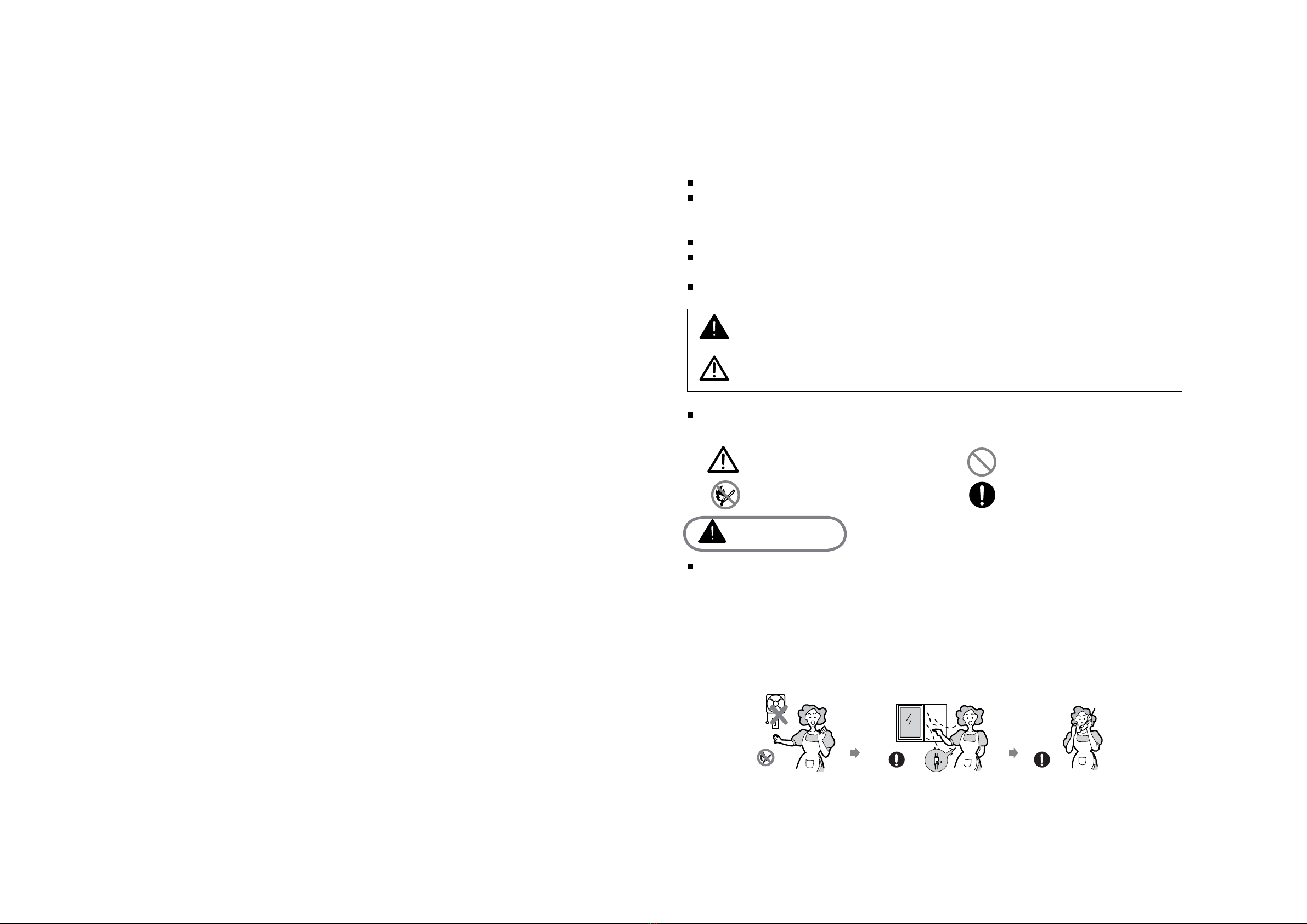
Danger/Warning
Caution Neglect of this mark may result in minor personal injury
or property damage.
Caution No Access
No Fire Tool Must Do
Danger
- Do not turn on the light.
- Do not switch on/off any electrical appliance and do not touch any electric plug.
- Do not use a telephone.
1Stop using the product and close the middle valve.
2 Open the window to ventilate.
3Contact our service centre by using a phone outside.
ci l ragnet torfol lems(kaelsagehtl lemsnacuoytahtos,natpacremsniatnocsagleufehT*
or egg) even where only 1/1000 of the gas is in the air.
The following marks are used in the Instruction Manual
as follows:
3
If gas seems to leak,take the actions as follow:
Neglect of this mark may result in severe personal injury
or death.
Please take the time to read this Instruction Manual before installing or using the appliance.
7KLVLQVWUXFWLRQERRNOHWPXVWEHNHSWZLWKWKHDSSOLDQFHIRUDQ\IXWXUHUHIHUHQFH.
If the appliance is sold or transferred to another person,ensure the booklet is passed on to
the new user.
7KHPDQXIDFWXUHUGHFOLQHVDQ\OLDELOLW\VKRXOGWKHVHVDIHW\PHDVXUHVQRWEHREVHUYHG
TKHIROORZLQJPDUNVDUHPDGHWREHHDVLO\XQGHUVWRRGVRWKDW\RXFDQSUHYHQWDQ\
accident caused by misuse in advance, and use the appliance more conveniently.
RHDGWKHIROORZLQJFRQWHQWVWKRURXJKO\DQGHQVXUH\RXXQGHUVWDQGWKHP.
6 7
General Safety
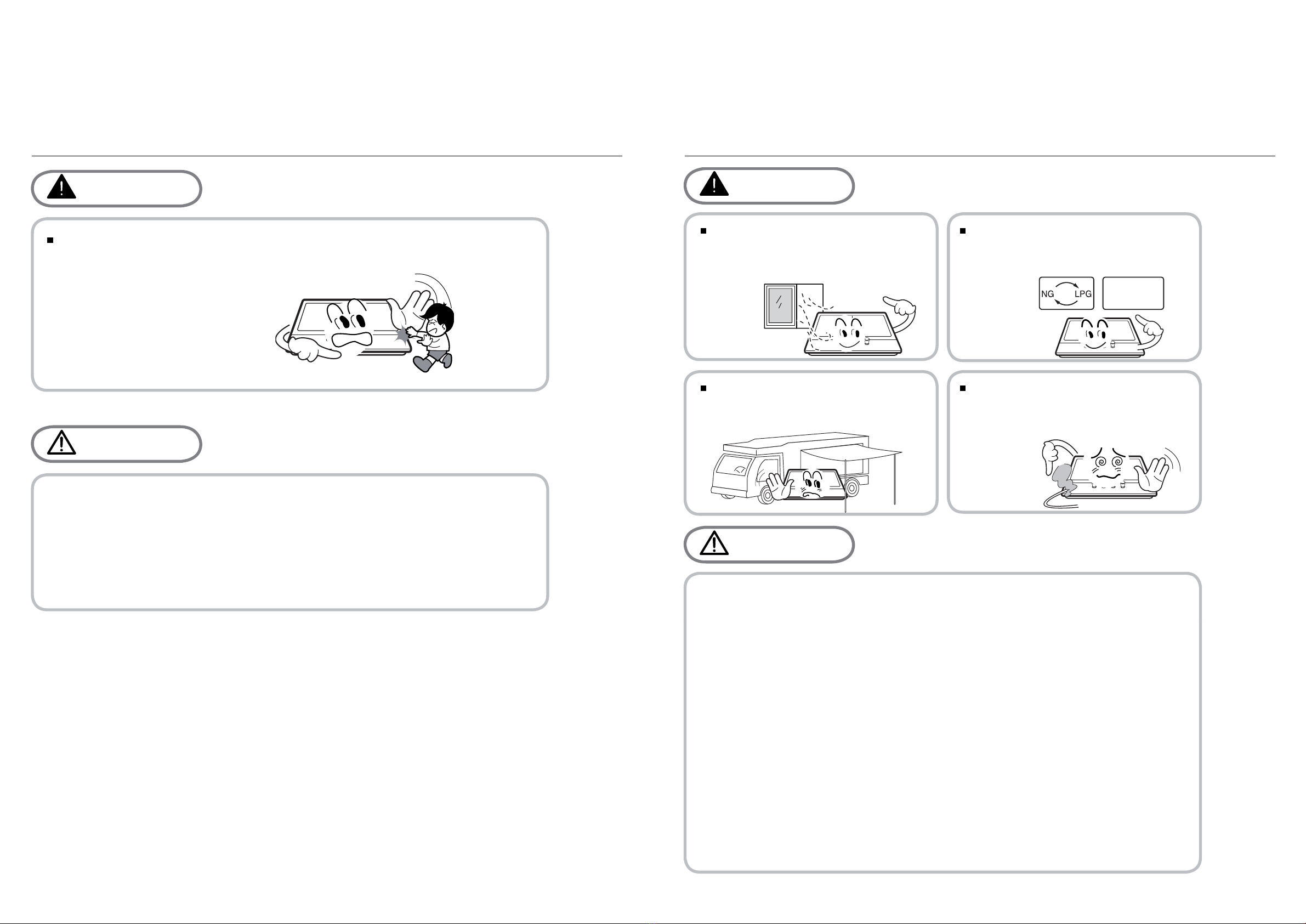
Child and People Safety
Do not allow children to play near or with the appliance.
The appliance gets hot when it is in use.
Children should be kept away until it has cooled.
Warning
Caution
5
Ŷ7KLVDSSOLDQFHLVGHVLJQHGWREHRSHUDWHGE\DGXOWV
Ŷ&KLOGUHQFDQDOVRLQMXUHWKHPVHOYHVE\SXOOLQJSDQVRUSRWVRIIWKHDSSOLDQFH
Ŷ7KLVDSSOLDQFHLVQRWLQWHQGHGIRUXVHE\FKLOGUHQRURWKHUSHUVRQVZKRVHSK\VLFDO
VHQVRU\RUPHQWDOFDSDELOLWLHVRUODFNRIH[SHULHQFHDQGNQRZOHGJHSUHYHQWVWKHP
from using the appliance safety without supervision or instruction by a responsible
person to ensure that they can use the appliance safety.
Installation Safety
Installation
Warning
This appliance shall be installed in
accordance with regulations in force
and only used in a well ventilated
space.
Prior to installation,ensure that the
gas and electrical supply complies
with the type stated on the rating
plate.
Where this appliance is installed in
marine craft or in caravans, it should
not be used as a space heater.
The gas pipe and electrical cable
must be installed in such a way that
they do not touch any parts or the
appliance.
Caution
4
220V-240V
Ŷ7KLVDSSOLDQFHVKRXOGEHLQVWDOOHGE\DTXDOL¿HGWHFKQLFLDQRULQVWDOOHU
Ŷ7KHDGMXVWPHQWFRQGLWLRQVIRUWKLVDSSOLDQFHDUHVWDWHGRQWKHODEHORUGDWDSODWH
Ŷ5HPRYHDOOSDFNDJLQJEHIRUHXVLQJWKHDSSOLDQFH
Ŷ$IWHUXQSDFNLQJWKHDSSOLDQFHPDNHVXUHWKHSURGXFWLVQRWGDPDJHGDQGWKDWWKH
connection cord is in perfect condition. Otherwise, contact the dealer before
installing the appliance.
Ŷ7KHDGMDFHQWIXUQLWXUHDQGDOOPDWHULDOVXVHGLQWKHLQVWDOODWLRQPXVWEHDEOHWR
ZLWKVWDQGDPLQLPXPWHPSHUDWXUHRIÛ&DERYHWKHDPELHQWWHPSHUDWXUHRIWKH
room it is located in, whilst in use.
Ŷ,QWKHHYHQWRIEXUQHUÀDPHVEHLQJDFFLGHQWDOO\H[WLQJXLVKHGWXUQRIIWKHEXUQHU
control and do not attempt to re-ignite the burner for at least one minute.
Ŷ
The use of a gas cooking appliance results in the production of heat and moisture in the
room in which it is installed. Ensure that the kitchen is well ventilated: keep natural
YHQWLODWLRQKROHVRSHQRULQVWDOODPHFKDQLFDOYHQWLODWLRQGHYLFHPHFKDQLFDOH[WUDFWRUKRRG
Ŷ3URORQJHGLQWHQVLYHXVHRIWKHDSSOLDQFHPD\FDOOIRUDGGLWLRQDOYHQWLODWLRQIRU
H[DPSOHRSHQLQJRIDZLQGRZRUPRUHHIIHFWLYHYHQWLODWLRQIRUH[DPSOHLQFUHDVLQJ
the level of mechanical ventilation where present.
Do not use this appliance
as a space heater.
This appliance is not suitable for installation with aftermarket lids or covers.
Installation
Warning
This appliance shall be installed in
accordance with regulations in force
and only used in a well ventilated
space.
Prior to installation,ensure that the
gas and electrical supply complies
with the type stated on the rating
plate.
Where this appliance is installed in
marine craft or in caravans, it should
not be used as a space heater.
The gas pipe and electrical cable
must be installed in such a way that
they do not touch any parts or the
appliance.
Caution
4
220V-240V
Ŷ7KLVDSSOLDQFHVKRXOGEHLQVWDOOHGE\DTXDOL¿HGWHFKQLFLDQRULQVWDOOHU
Ŷ7KHDGMXVWPHQWFRQGLWLRQVIRUWKLVDSSOLDQFHDUHVWDWHGRQWKHODEHORUGDWDSODWH
Ŷ5HPRYHDOOSDFNDJLQJEHIRUHXVLQJWKHDSSOLDQFH
Ŷ$IWHUXQSDFNLQJWKHDSSOLDQFHPDNHVXUHWKHSURGXFWLVQRWGDPDJHGDQGWKDWWKH
connection cord is in perfect condition. Otherwise, contact the dealer before
installing the appliance.
Ŷ7KHDGMDFHQWIXUQLWXUHDQGDOOPDWHULDOVXVHGLQWKHLQVWDOODWLRQPXVWEHDEOHWR
ZLWKVWDQGDPLQLPXPWHPSHUDWXUHRIÛ&DERYHWKHDPELHQWWHPSHUDWXUHRIWKH
room it is located in, whilst in use.
Ŷ,QWKHHYHQWRIEXUQHUÀDPHVEHLQJDFFLGHQWDOO\H[WLQJXLVKHGWXUQRIIWKHEXUQHU
control and do not attempt to re-ignite the burner for at least one minute.
Ŷ
The use of a gas cooking appliance results in the production of heat and moisture in the
room in which it is installed. Ensure that the kitchen is well ventilated: keep natural
YHQWLODWLRQKROHVRSHQRULQVWDOODPHFKDQLFDOYHQWLODWLRQGHYLFHPHFKDQLFDOH[WUDFWRUKRRG
Ŷ3URORQJHGLQWHQVLYHXVHRIWKHDSSOLDQFHPD\FDOOIRUDGGLWLRQDOYHQWLODWLRQIRU
H[DPSOHRSHQLQJRIDZLQGRZRUPRUHHIIHFWLYHYHQWLODWLRQIRUH[DPSOHLQFUHDVLQJ
the level of mechanical ventilation where present.

8 9
Safety During Use Safety During Use
During Use
Ŷ'RQRWVSUD\DHURVROVLQWKHYLFLQLW\RI
this appliance while it is in operaiton. ‘ ’ position when not in use.
Caution
7
Ŷ 'RQRWXVHRUVWRUHÀDPPDEOH materials
in the storage drawer near this
appliance.
Ŷ3HULVKDEOHIRRGSODVWLFLWHPVDQG
aerosols may be affected by heat and
should not stored above or below the
appliance.
Ŷ(QVXUHWKHFRQWURONQREVDUHLQWKH
This appliance is intended for domestic cooking only.It is not designed for commercial
or industrial purposes.
Prolonged intensive use of the appliance may call for additional ventilation,for example
opening of a window, or increasing the level of mechanical ventilation where present.
Ŷ8VHKHDWUHVLVWDQWSRWKROGHUVRUJORYHVZKHQKDQGOLQJKRWSRWVDQGSDQV
Ŷ'RQRWOHWSRWKROGHUVFRPHQHDURSHQÀDPHVZKHQOLIWLQJFRRNZDUH
Ŷ7DNHFDUHQRWWROHWSRWKROGHUVRUJORYHVJHWGDPSRUZHW DVWKLVFDXVHVKHDWWRWUDQVIHU
WKURXJKWKHPDWHULDOTXLFNHUZLWKWKHULVNRIEXUQLQJ\RXUVHOI
ŶOQO\HYHUXVHWKHEXUQHUVDIWHUSODFLQJSRWVDQGSDQVRQWKHP'RQRWKHDWXSDQ\HPSW\
is made of glass-cracked, switch off the appliance to avoid defeat electrocution.
Ŷ 7RPLQLPLVHWKHSRVVLELOLW\RIEXUQVLJQLWLRQRIÀDPPDEOHPDWHULDOVDQGVSLOODJHWXUQ
FRRNZDUHKDQGOHVWRZDUGWKHVLGHRUFHQWHURIWKHWRSSODWHZLWKRXWH[WHQGLQJRYHU
adjacent burners.
Ŷ$OZD\VWXUQEXUQHUFRQWUROVRIIEHIRUHUHPRYLQJFRRNZDUH
Ŷ&DUHIXOO\ZDWFKIRRGVEHLQJIULHGDWDKLJKÀDPHVHWWLQJ
Ŷ$OZD\VKHDWIDWVORZO\DQGZDWFKDVLWKHDWV
Ŷ)RRGVIRUIU\LQJVKRXOGEHDVGU\DVSRVVLEOH)URVWRQIUR]HQIRRGVRUPRLVWXUHRQIUHVK
Ŷ:KHQXVLQJJODVVFRRNZDUH PDNHVXUHLWLVGHVLJQHGIRUWRSSODWHFRRNLQJ
If the surface
using the appliance.
Do not use a tea towel or similar materials in place of a pot holder.Such cloths can
catch fire on a hot burner.
foods can cause hot fat to bubble up and over the sides of the pan.
Never try to move a pan of hot fat,especially a deep fat fryer.Wait until the fat is
completely cool.
pots or pans.
Ŷ1HYHUXVHSODVWLFRUDOXPLQLXPIRLOGLVKHVRQWKHDSSOLDQFH
Ŷ:KHQXVLQJ RWKHUHOHFWULFDODSSOLDQFHV HQVXUHWKHFDEOHGRHVQRWFRPHLQWRFRQWDFWZLWK
the appliance surfaces of the cooking appliance.
Ŷ,I\RXKDYHDQ\PHFKDQLFDOSDUWVHJDQDUWL¿FDOKHDUWLQ\RXUERG\FRQVXOWDGRFWRUEHIRUH
During Use
Warning
The use of a gas cooking appliance
results in the production of heat and
moisture in the room in which it is
installed. Ensure that the kitchen is
well ventilated : keep natural
ventilation holes open or install a
mechanical ventilation device
(mechanical
extractor hood).
Never leave the appliance unattended
when cooking.
Burner
panel is not designed to operate from
an external timer or separate remote
control system.
6
Ŷ2QO\XVHWKHDSSOLDQFHIRUSUHSDULQJ
food.
LQcontact with water. Do not operate
this appliance with wet hands.
Ŷ'RQRWXVHWKLVDSSOLDQFHLILW comes
Ŷ7KHKHDWLQJDQGFRRNLQJVXUIDFHVRI
the appliance become hot when they
are in use, take all due precautions.
Ŷ'RQRWXVHODUJHFORWKVWHDWRZHOVRU
similar as the ends could touch the
ÀDPHVDQGFDWFK¿UH
Ŷ8QVWDEOHRUPLVVKDSHQSDQVVKRXOG
not be used on the appliance as they
can cause an accident by tipping or
spillage.

10 11
Cleaning and Service
Environmental Information
unusable, by cutting off the cable.
disposed with other household wastes at the end of its working life. To prevent
possible harm to the environment or human health from uncontrolled waste disposal,
please separate this from other types of wastes and recycle it responsibly to promote
the sustainable reuse of material resources.
agents.
Warning
and cooled.
clean the appliance.
or serviced by an authorised Service
Engineer and only genuine approved
spare parts should be used.
Caution
8
Ŷ1HYHUXVHDEUDVLYHRUFDXVWLFcleaning Ŷ 7KLVDSSOLDQFHVKRXOGRQO\EHrepaired
Ŷ%HIRUHDWWHPSWLQJWRFOHDQWKHDSSOLDQFHLWVKRXOGEHGLVFRQQHFWHGIURPWKHPDLQV
Ŷ<RXVKRXOGQRWXVHDVWHDPMHWRUDQ\RWKHUKLJKSUHVVXUHFOHDQLQJHTXLSPHQWWR
Ŷ$IWHULQVWDOODWLRQSOHDVHGLVSRVHRIWKHSDFNDJLQJ
with due regard to safety and the environment.
Ŷ:KHQGLVSRVLQJRIDQROGDSSOLDQFHPDNHLW
Ŷ7KLVPDUNLQJVKRZQRQWKHSURGXFWRULWVOLWHUDWXUHLQGLFDWHVWKDWLWVKRXOGQRWEH
Ŷ+RXVHKROGXVHUVVKRXOGFRQWDFWHLWKHUWKHUHWDLOHUZKHUHWKH\SXUFKDVHGWKLVSURGXFW
RUWKHLUORFDOJRYHUQPHQWRI¿FHIRUGHWDLOVRIZKHUHDQGKRZWKH\FDQWDNHWKLVLWHP
for environmentally safe recycling.
Ŷ%XVLQHVVXVHUVVKRXOGFRQWDFWWKHLUVXSSOLHUDQGFKHFNWKHWHUPVDQGFRQGLWLRQVRI
WKHSXUFKDVHFRQWUDFW7KLVSURGXFWVKRXOGQRWEHPL[HGZLWKRWKHUFRPPHUFLDO
wastes for disposal.
Correct Disposal of This Product
(Waste Electrical & Electronic Equipment)
Safety During
Maintenance Your Cooktop
Model: ICG905WS
Product Dimensions (H, W, D): 860mm, 510mm, 90mm
Electric supply: 220-240Vac, 50Hz-60Hz, 2W
Burners: 1 × Triple-Crown
1 × Rapid
2 × Semi-rapid
1 × Auxiliary
∑Qn 11.1kW
Top Plate: Stainless Steel
Ignition Device: Continuous Ignition Type
Gas Connection: G1/2 thread

12 13
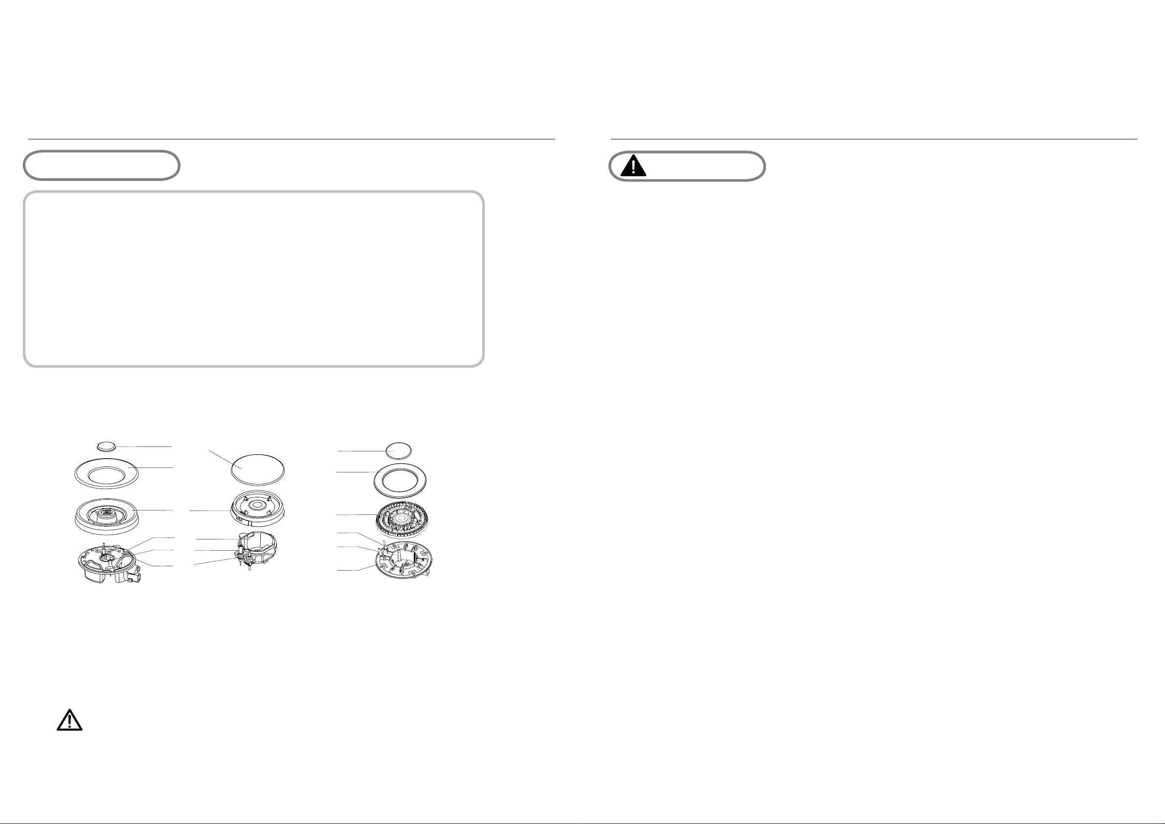
A
How to Use the appliance
ccessories
Description of the appliance
Black circle: gas off
Large flame: maximum setting
Small flame: minimum setting
Automatic ignition with flame failure safety device
10
Bracket (4) Sponge (4)
Screw
(4)
Elbow
(1) Auxiliary pan support (1)
(5)
Instruction
Manual (1)
Voltage regulator valve (1)
Pressure joint(1)
The appliance is fitted with a flame failure safety device on each burner, which
is designed to stop the flow of gas to the burner head in the event of the flame
going out.
Injector
The minimum setting is at the end of the anti-clockwise rotation of the control handle.
All operation positions must be selected between the maximum and minimum position.
The symbol on the control panel,next to the control handle will indicate which burner it
operates.
7KHIROORZLQJV\PEROVZLOODSSHDURQWKHFRQWUROSDQHOQH[WWRHDFKFRQWUROKDQGOH
Your CooktopYour Cooktop
Accessories The control panel
How to use the appliance
How to Use the appliance
Automatic ignition with flame failure safety device
The appliance is fitted with a flame failure safety device on each burner, which
is designed to stop the flow of gas to the burner head in the event of the flame
going out.
To ignite a burner:
o Press in the control knob of the burner that you wish to light and turn it
anti-clockwise to the maximum position.
o If youkeep the control knob depressed, the automatic ignition for the
burner will operate.
o
oAfter this 15-second interval, to regulate the flame you should continue
turning the control knob anti-clockwise until the flame is at a suitable level.
The operating position MUST be at a position between the maximum and
minimum position.
oTo switch the burner off, turn the control knob fully clockwise to the gas
off position.
oIn case of power failure, the burners can be lit by carefully using a match.
11
You should hold down the control knob for 15 seconds after the flame on
the burner has lit. If after 15s the burner has not lit, stop operating the
device and open the compartment door and/or wait at least 1 min before
attempting a further ignition of the burner.
Model: ICG905WS
A
How to Use the appliance
ccessories
Description of the appliance
Black circle: g
as off
Large flame:
maximum setting
Small flame
: minimum setting
Automatic ignition with flame failure safety device
10
Bracket (4) Sponge (4)
Screw
(4)
Elbow
(1) Auxiliary pan support (1)
(5)
Instruction
Manual (1)
Voltage regulator valve (1)
Pressure joint(1)
The appliance is fitted with a flame failure safety device on each burner, which
is designed to stop the flow of gas to the burner head in the event of the flame
going out.
Injector
The minimum setting is at the end of the anti-clockwise rotation of the control handle.
All operation positions must be selected between the maximum and minimum position.
The symbol on the control panel,next to the control handle will indicate which burner it
operates.
7KHIROORZLQJV\PEROVZLOODSSHDURQWKHFRQWUROSDQHOQH[WWRHDFKFRQWUROKDQGOH
12
Black circle: gas off
Large flame: maximum setting
Small flame: minimum setting
Automatic ignition with flame failure safety device
10
Bracket (4) Sponge (4)
Screw
(4)
Elbow
(1) Auxiliary pan support (1)
(5)
Instruction
Manual (1)
Voltage regulator valve (1)
Pressure joint(1)
The appliance is fitted with a flame failure safety device on each burner, which
is designed to stop the flow of gas to the burner head in the event of the flame
going out.
Injector
The minimum setting is at the end of the anti-clockwise rotation of the control handle.
All operation positions must be selected between the maximum and minimum position.
The symbol on the control panel,next to the control handle will indicate which burner it
operates.
7KHIROORZLQJV\PEROVZLOODSSHDURQWKHFRQWUROSDQHOQH[WWRHDFKFRQWUROKDQGOH
Your Cooktop
Accessories
How to use the appliance
cle: g
as off
maximum setting
ame
: minimum setting
ignition with flame failure safety device
10
Auxiliary (1)
ure safety device on each burner, which
he burner head in the event of the flame

14 15
Cooking Tips
Cleaning
and Maintenance
Safety and Energy saving advice
- The diameter of the bottom of the pan should correspond to that of the burner.
BURNERS
200mm 240mm
200mm 240mm
160mm
NO YES
120mm 160mm
180mm
12
Triple-Crown
Rapid
Semi-Rapid
Auxiliary
PANS
min. max.
Do not use small diameter cookware on large
burners.
The flame should never come up the sides of
the cookware.
Avoid cooking without a lid or with the
lid half off
-as this wastes energy
Do not use a pan with a convex or
concave bottom.
Do not place cookware on one side of a
burner,as it could tip over.
Do not use cookware with a large diameter
on the burners near the controls,which when
placed on the middle of the burner may
touch the controls or be so close to them
that they increase the temperature in this
area and may cause damage.
Never place cookware directly on top of the
burner.
Do not place anything,eg.flame
tamer,asbestos mat,between pan and pan
support as serious damage to the appliance
may result.
Do not use excessive weight and do not
hit the cooktop with heavy objects.
Always use cookware that is
suitable for each burner, to avoid
wasting gas and discolouring the
cookware.
Place a lid on the cookware.
Only use pots,saucepans and
frying pans with a thick,flat
bottom.
Always place the cookware right
over the burners,not to one
side.
Place the cookware on top of
the trivet.
Handle cookware carefully when
they are on the burner.
Ŷ'RQRWXVHFRRNZDUH
WKDW
RYHUODSVWKHHGJH of the
burner.
It is not recommended to use roasting pans,frying pans or grill stones
heated simultaneously on several burners because the resulting heat
build-up may damage the appliance.
Do not touch the top plate and trivet whilst in use for a certain period
after use.
As soon as a liquid starts boiling,turn down the flame so that it will
barely keep the liquid simmering.
Cleaning and Maintenance
Soft cloth
Neutral Detergent
Nylon Brush
13
Edible Oil
Abrasive
Detergent
Thinner/Benzene
Metal Brush
Acidic/Alkali
Ŷ7DNHRIIWKH3DQVXSSRUW
Ŷ&OHDQWKHVHDQGWKHFRQWUROKDQGOHVZLWKDGDPSFORWKZDVKLQJXSOLTXLGDQGZDUP
water. For stubbon soiling, soak beforehand.
Ŷ'U\HYHU\WKLQJZLWKDFOHDQVRIWFORWK
3DQVXSSRUW&RQWUROKDQGOHV
Ŷ5HJXODUO\ZLSHRYHUWKHWRSSODWHXVLQJDVRIWFORWKZHOO
LQZDUPZDWHUWR
ZKLFKDOLWWOHZDVKLQJXSOLTXLGKDVEHHQDGGHG
Ŷ'U\WKHWRSSODWHWKRURXJKO\DIWHUFOHDQLQJ
Ŷ7KRURXJKO\UHPRYHVDOW\IRRGVRUOLTXLGVIURPWKHKREDVVRRQDVSRVVLEOHWRDYRLG
the risk of corrosion.
Ŷ6WDLQOHVVVWHHOSDUWVRIWKHDSSOLDQFHPD\EHFRPHGLVFRORXUHGRYHUWLPH7KLVLV
normal because of the high temperatures. Each time the appliance is used these
parts should be cleaned with a product that is suitable for stainless steel.
7RSSODWH
Ŷ &OHDQLQJRSHUDWLRQVPXVWRQO\EHFDUULHGRXWZKHQWKHDSSOLDQFH is
completely cool.
Ŷ7KHDSSOLDQFHVKRXOGEHGLVFRQQHFWHGIURP\RXUPDLQVVXSSO\EHIRUH
FRPPHQFLQJDQ\FOHDQLQJSURFHVV
Ŷ&OHDQWKHDSSOLDQFHUHJXODUO\SUHIHUDEO\DIWHUHDFKXVH
Ŷ$EUDVLYHFOHDQHUVRUVKDUSREMHFWVZLOOGDPDJHWKHDSSOLDQFHVXUIDFH
\RXVKRXOGFOHDQLWXVLQJZDWHUDQGDOLWWOHZDVKLQJXSOLTXLG
16 17
Operation Instructions
Cleaning
and Maintenance
Cleaning and Maintenance
14
212
33
44
57
66
75
1.Place the flame spreader ( 4 ) on to the burner cup ( 5 ) so that the ignition device
and the flame supervision device extend through their respective holes in the flame
spreader.The flame spreader must click into place correctly.
2.Position the burner lid ( 1,2,3 ) onto the flame speader ( 4 ) so that the retaining pins
fit into their respective recesses.
Ŷ5HPRYHWKHEXUQHUOLGVDQG)ODPH6SUHDGHUVE\SXOOLQJWKHPXSZDUGVDQGDZD\
from the top plate.
Ŷ6RDNWKHPLQKRWZDWHUDQGDOLWWOH detergent or washing up liqui.
Ŷ$IWHUFOHDQLQJDQGZDVKLQJWKHPZLSHDQGGU\WKHPFDUHIXOO\0DNHVXUHWKDWWKH
ÀDPHKROHVDUHFOHDQDQGFRPSOHWHO\GU\
Ŷ:LSHWKH¿[HGSDUWVRIWKHEXUQHUFXSZLWKDGDPSFORWKDQGGU\DIWHUZDUGV
Ŷ*HQWO\ZLSHWKHLJQLWLRQGHYLFHDQGÀDPHVXSHUYLVLRQGHYLFHZLWKDZHOOZUXQJRXW
cloth and wipe dry with a clean cloth.
Ŷ%HIRUHSODFLQJWKHEXUQHUVEDFNRQWKHWRSSODWHPDNHVXUHWKDWWKHLQMHFWRULVQRW
blocked.
%851(56
ʄ5HDVVHPEOHWKH$X[LOLDU\6HPL5DSLG5DSLGDQG
7ULSOH&URZQEXUQHUVDVIROORZV
5HSODFHSDUWVLQWKHFRUUHFWRUGHUDIWHUFOHDQLQJ
'RQRWPL[XSWKHWRSDQGERWWRP
7KHORFDWLQJSLQVPXVW¿WH[DFWO\LQWRWKHQRWFKHV
Warnings
Using instructions
15
Ŷ'RQRWPRGLI\WKLVDSSOLDQFH
Ŷ7KLVDSSOLDQFHPXVWEHLQVWDOOHGE\DQDXWKRULVHGWHFKQLFLDQRU
LQVWDOOHU
Ŷ3ULRUWRLQVWDOODWLRQHQVXUHWKDWWKHORFDOGLVWULEXWLRQFRQGLWLRQV
QDWXUHRIWKHJDVDQGJDVSUHVVXUHDQGWKHDGMXVWPHQWRIWKH
DSSOLDQFHDUHFRPSDWLEOH
Ŷ7KHDGMXVWPHQWFRQGLWLRQVIRUWKLVDSSOLDQFHDUHVWDWHGRQWKHODEHO
RUGDWDSODWH
Ŷ7KLVDSSOLDQFHLVQRWFRQQHFWHGWRDFRPEXVWLRQSURGXFWVHYDFXDWLRQ
LQVWDOODWLRQUHJXODWLRQV3DUWLFXODUDWWHQWLRQ VKRXOG
EH JL YHQ WRWKH
UHOHYDQWUHTXLUHPHQWVUHJDUGLQJYHQWLODWRQ
Ŷ%HIRUHLQVWDOOLQJWXUQRIIWKHJDVDQGHOHFWULFLW\VXSSO\WRWKH
DSSOLDQFH
Ŷ$OODSSOLDQFHVFRQWDLQLQJDQ\HOHFWULFDOFRPSRQHQWVPXVWEHHDUWKHG
Ŷ(QVXUHWKDWWKHJDVSLSHDQGHOHFWULFDOFDEOHDUHLQVWDOOHGLQVXFKD
ZD\WKDWWKH\GRQRWWRXFKDQ\SDUWVRIWKHapplianceZKLFK
may EHFRPHKRW
Ŷ*DVSLSHRUFRQQHFWRUVKRXOGQ¶WEHEHQWRUEORFNHGE\DQ\RWKHU
DSSOLDQFHV
Ŷ&KHFNWKHGLPHQVLRQVRIWKHDSSOLDQFHDVZHOODVWKHGLPHQVLRQVRI
WKHJDSWREHFXWLQWKHNLWFKHQXQLW
Ŷ7KHSDQHOVORFDWHGDERYHWKHZRUNVXUIDFHGLUHFWO\QH[WWRWKH
DSSOLDQFHPXVWEHPDGHRIQRQÀDPPDEOHPDWHULDO%RWKWKHVWUDWL
¿HGVXUIDFLQJDQGWKHJOXHXVHGWRVHFXUHLWVKRXOGEHKHDWUHVLVWDQW
WRSUHYHQWGHWHULRUDWLRQ
Ŷ7XUQRQDSSOLDQFHWDSDQGOLJKWHDFKEXUQHUV
&KHFNIRUDFOHDUEOXHÀDPHZLWKRXW\HOORZWLSSLQJ
,IEXUQHUVVKRZVDQ\DEQRUPDOLWLHVFKHFNWKHIROORZLQJ
%XUQHUOLGRQFRUUHFWO\
)ODPHVSUHDGHUSRVLWLRQHGFRUUHFWO\
%XUQHUYHUWLFDOO\DOLJQHGZLWKLQMHFWRUQLSSOH
Ŷ$IXOORSHUDWLRQDOWHVWDQGDWHVWIRUSRVVLEOHOHDNDJHVPXVWEHFDUULHG
RXWE\WKH¿WWHUDIWHUinstallation
Ŷ7KHÀH[LEOHKRVHVKDOOEH¿WWHGLQVXFKDZD\WKDWLWFDQQRWFRPHLQWR
FRQWDFWZLWKDPRYHDEOHSDUWRIWKHKRXVLQJXQLWDQGGRHVQRWSDVV
WKURXJKDQ\VSDFHVXVFHSWLEOHRIEHFRPLQJFRQJHVWHG
GHYLFH,WVKRXOG be installed and connected in accordance with current
Grease cranes produced at the factory to meet the requirement of all
life hob.
Ŷ
18 19
InstallationInstallation
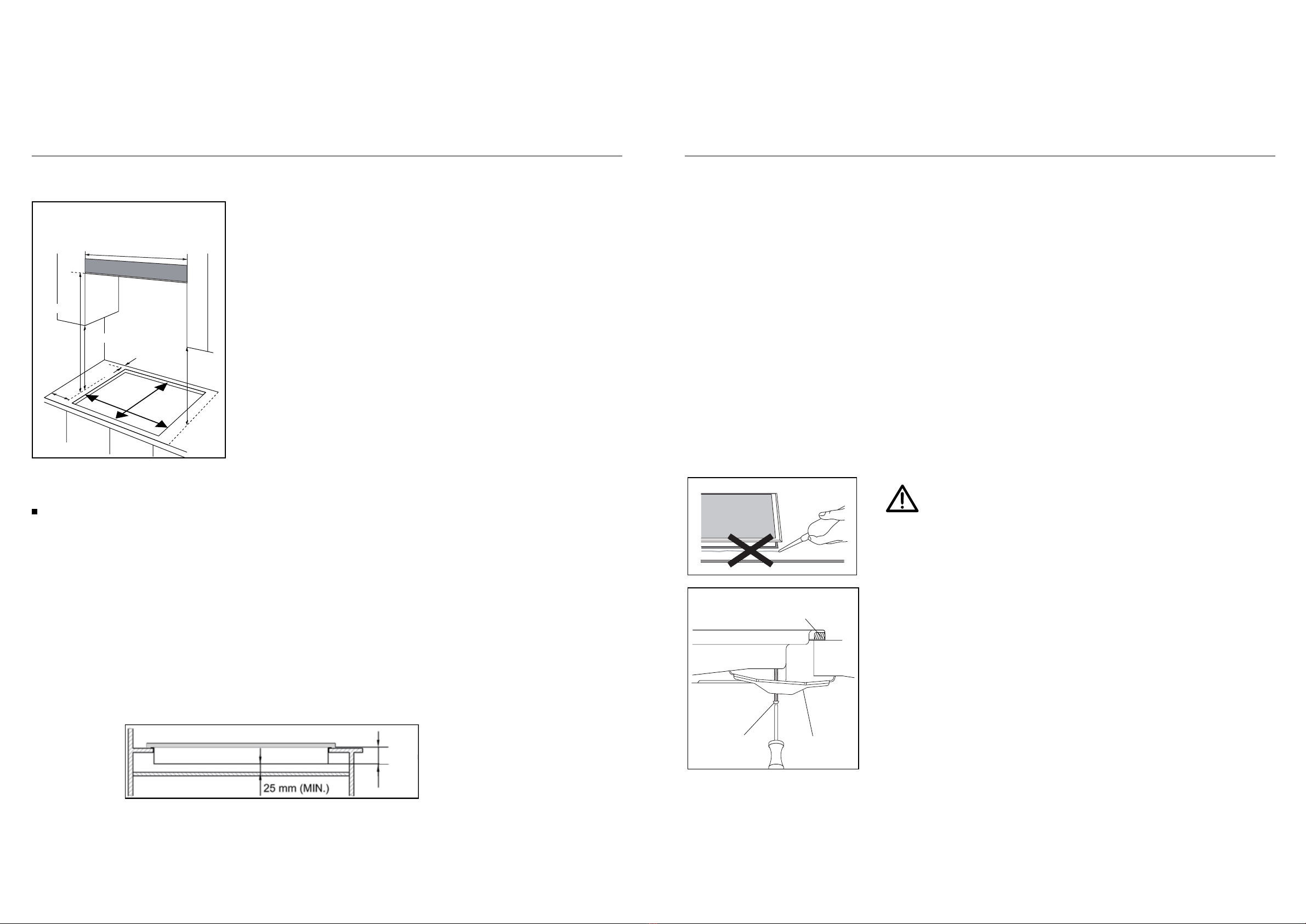
Positioning
The edges of the hob must be a minimum distance of mm from a side or
rear wall.
700 mm between the highest point of the hob surface (including the burners)
and the underside of any horizontal surface directly above it.
400 mm between the hob surfaces, providing that the underside of the
horizontal surface is in line with the outer edge of the hob. If the underside of
the horizontal surface is lower than 400 mm, then it must be at least 50 mm
away from the outer edges of the hob.
50 mm clearance around the appliance and between the hob surface and any
combustible materials.
45 mm
60
You must have a gap of at least 25 mm and at most 74 mm between
the underneath of the appliance and any surface that is below it.
16
o
o
o
o
o
CLEARANCES REQUIRED
WHEN FITTING THE HOB
WITH A COOKER HOOD ABOVE
600 mm
700mm
400mm
400mm
FO 0813
60mm
in
0
.
0mm
M
2
This appliance is to be built into a kitchen unit or 600mm worktop,providing
the following minium distances are allowed;
- An oven must have forced ventilation to install a hob above it.
- Check the dimensions of the oven in the installation manual.
- The cut out size must obey the indication.
4
73
mm
553mm
Installing the appliance
Sponge
Bottom view
The thickness of the sponge is 3 mm.
The width of the sponge is 10 mm.
of the screws.There are one set of screw holes in each
corner of the hob (H) .
Slightly tighten a screw (C) through the bracket (B) so
that the bracket is attached to the hob, but so that you
can still adjust the position
.
.2 Carefully turn the hob back over and then gently lower
it into the aperture hole that you have cut out.
.3 On the underneath of the hob, adjust the brackets into
a position that is suitable for your worktop.
Then fully tighten the screws (C) to secure the hob into
position.
(A) SEALING STRIP
(C) SCREW (B) BRACKET
17
Remove the pan supports, the burner lid
and flame spreader and carefully turn the
appliance upside down and place it on a
cushioned mat.
Take care that the Ignition devices and
flame supervision devices are not damaged
in this operation.
2. Apply the sponge provided around the
edge of the appliance.
3.
1.
Do not leave a gap in the sealing agent or
overlap the thickness.
3ODFHWKHEUDFNHW %RYHUWKHKROHVWKDWPDWFKWKHVL]H
7KLVZLOOPDNHLWGLI¿FXOWWRUHPRYHWKH
DSSOLDQFHIURPWKHDSHUWXUHLQIXWXUH
SDUWLFXODUO\LILWQHHGVWREHVHUYLFHG
Do not use a silicon sealant to seal the
appliance against the aperture.
Positioning
The edges of the hob must be a minimum distance of mm from a side or
rear wall.
700 mm between the highest point of the hob surface (including the burners)
and the underside of any horizontal surface directly above it.
400 mm between the hob surfaces, providing that the underside of the
horizontal surface is in line with the outer edge of the hob. If the underside of
the horizontal surface is lower than 400 mm, then it must be at least 50 mm
away from the outer edges of the hob.
50 mm clearance around the appliance and between the hob surface and any
combustible materials.
45 mm
60
You must have a gap of at least 25 mm and at most 74 mm between
the underneath of the appliance and any surface that is below it.
16
o
o
o
o
o
CLEARANCES REQUIRED
WHEN FITTING THE HOB
WITH A COOKER HOOD ABOVE
900mm
700mm
400mm
400mm
FO 0813
60mm
490mm
in
0
.
0mm
M
2
This appliance is to be built into a kitchen unit or 600mm worktop,providing
the following minium distances are allowed;
- An oven must have forced ventilation to install a hob above it.
- Check the dimensions of the oven in the installation manual.
- The cut out size must obey the indication.
815mm
Model: ICG905WS
Installing the appliance
Sponge
Bottom view
The thickness of the sponge is 3 mm.
The width of the sponge is 10 mm.
of the screws.There are one set of screw holes in each
corner of the hob (H) .
Slightly tighten a screw (C) through the bracket (B) so
that the bracket is attached to the hob, but so that you
can still adjust the position
.
.2 Carefully turn the hob back over and then gently lower
it into the aperture hole that you have cut out.
.3 On the underneath of the hob, adjust the brackets into
a position that is suitable for your worktop.
Then fully tighten the screws (C) to secure the hob into
position.
(A) SEALING STRIP
(C) SCREW (B) BRACKET
17
Remove the pan supports, the burner lid
and flame spreader and carefully turn the
appliance upside down and place it on a
cushioned mat.
Take care that the Ignition devices and
flame supervision devices are not damaged
in this operation.
2. Apply the sponge provided around the
edge of the appliance.
3.
1.
Do not leave a gap in the sealing agent or
overlap the thickness.
3ODFHWKHEUDFNHW %RYHUWKHKROHVWKDWPDWFKWKHVL]H
7KLVZLOOPDNHLWGLI¿FXOWWRUHPRYHWKH
DSSOLDQFHIURPWKHDSHUWXUHLQIXWXUH
SDUWLFXODUO\LILWQHHGVWREHVHUYLFHG
Do not use a silicon sealant to seal the
appliance against the aperture.
20 21
InstallationInstallation
Gas Connection Gas Connection
Gas Connection
18
Keep away from inflammable materials around appliance.
Before work, put on gloves.
CAUTION
Cool off the appliance for a while right after using appliance for your safety
because you can get burners by high temperature from the appliances.
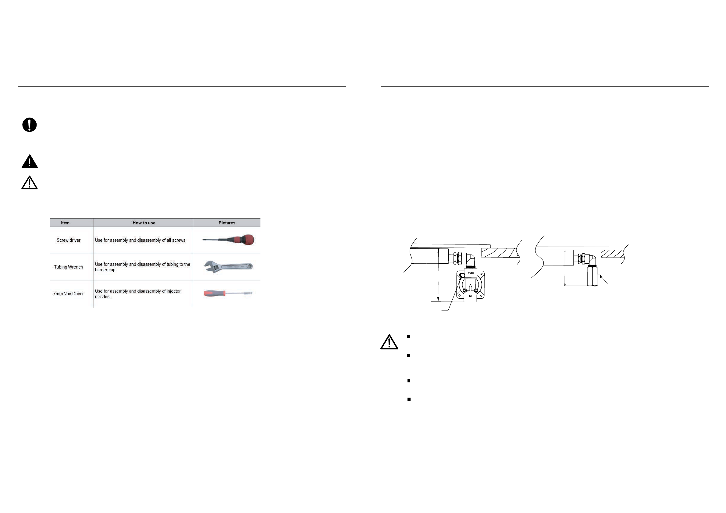
B: Look tightly a replaceable gas-type fitting onto the main gas tube.
Turn off power for safety and appliance protection. Close middle valve to
prevent gas leakage.
Most of the tools that you might need are shown below. Some are optional.
Replacement of gas-type fitting
Tool: Open-end wrench
Steps for operation:
A: Disassemble with a wrench the gas-type fittings from main gas tube.
When you disassemble/assemble gas connection, use 2 spanners. One for fixing gas
connection elbow, the other for tightening gas hose.
Ŷ7KLVDSSOLDQFHPXVWEHLQVWDOOHGDQGFRQQHFWHGLQDFFRUGDQFHZLWKLQVWDOOD
WLRQUHJXODWLRQVLQIRUFHLQWKHFRXQWU\LQZKLFKWKHDSSOLDQFHLVWREHXVHG
Ŷ7KLVDSSOLDQFHLVVXSSOLHGWRUXQRQQDWXUDOJDVRQO\DQGFDQQRWEHXVHGRQ
DQ\RWKHUW\SHRIJDVZLWKRXWPRGL¿FDWLRQ&RQYHUVLRQIRUXVHRQ/3*DQG
RWKHUJDVHVPXVWRQO\EHXQGHUWDNHQE\DTXDOL¿HGSHUVRQ
Gas Connection
Statutory requirements
This installation must conform with the following:
■Manufacturer’s Installation instructions
■Local Gas Fitting Regulations
■Municipal Building Codes
■Refer to AS/NZS 5601.1 for Gas Installations
■S.A.A. Wiring Code
■Local Electrical Regulations
■Any other statutory regulations
Preparing to install
Refer to AS/NZS 5601.1 for piping size details. These built-in cooktops are intended to
be inserted in a benchtop cutout. Only an officially authorised technician should
connect the appliance. Before you begin, turn off the gas and electricity supply.
19
A full operational test and a test for possible leakages must be
carried out by the fitter after installation.
Access to the whole length of the connection hose must be possible
and the gas hose must be replaced before its use before the end of
service life (indicated on the hose.)
Before Leaving-Check all connections for gas leaks with soap and
water.
DO NOT use a naked flame for detecting leaks. Ignite all burners both
individually and concurrently to ensure correct operation of gas
valves, burners and ignition. Turn gas taps to low flame position and
observe stability of the flame for each burner individually and all
together. Adhere the duplicate data plate to an accessible location
near the hotplate. When satisfied with the hotplate, please instruct
the user on the correct method of operation. In case the appliance
fails to operate correctly after all checks have been carried out, refer
to the auth orised service provider in your area.
Natural gas connection
95
115
LPG gas connection
pressure test point
pressure test point
22 23
InstallationInstallation
Gas Connection Gas Specification
Where a flexible hose assembly is used, ensure it is
approved to AS/NZS 1869, Class B. Any hose assembly
used must be restrained from accidental contact with
the flue outlet of an under bench oven.
This hose assembly shall be suitable for connection to a
fixed consumer piping outlet located as follows:
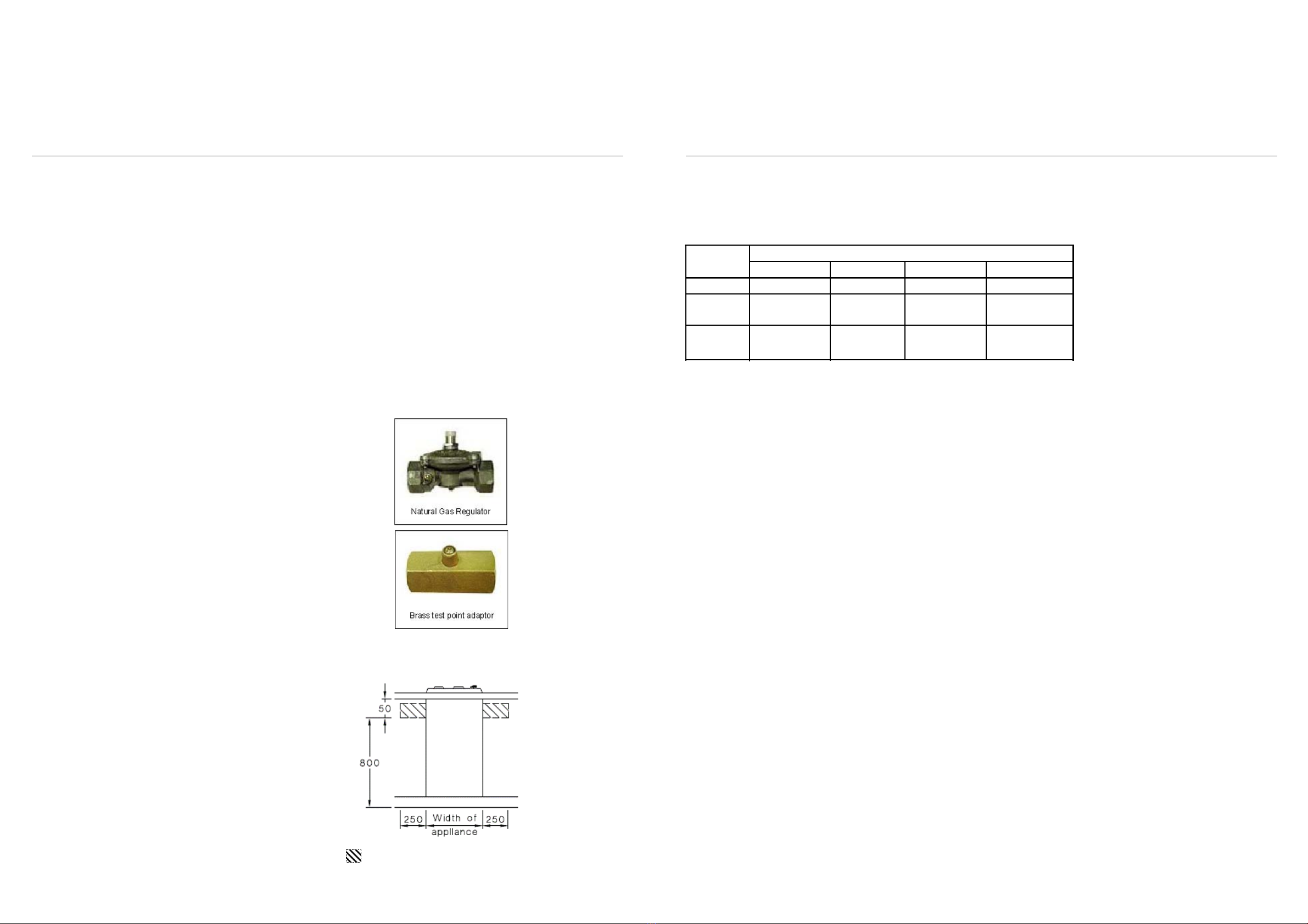
Hotplates at a point 800 mm to 850 mm above the floor
and in the region outside the width of the appliance to a
distance of 250 mm.
After connecting to gas, check for leaks using soapy
solution, never a naked flame. Inlet connection region for flexible hose
Gas Connection
Install in accordance with relevant gas standards and/or codes of
practice applicable.
Connect the elbow fitting to the appliance gas manifold
connection, and check that seals between the elbow and
manifold connection are in placeand in good condition.
For Natural gas: connect the natural gas appliance
regulator (pictured opposite) with integral test point using
approved gas thread tape or compound to the elbow
fitting.
For Universal LPG: connect the brass test point adaptor
(pictured opposite) using approved gas thread tape or
compound to the elbow fitting.
Ensure the supply connection point, test point and natural gas
regulator adjustment screw (for Natural gas installation) are
accessible for testing and/or adjustment with the hotplate in
the installed position.
20
■
■
■
Flexible Hose: If installing with a hose assembly, it must comply with AS/NZS
1869,10mmID,class B or D,no more than 1mm long and installed in
accordance with AS/NZS 5601.1.
Ensure that the hose does not contact the hot surfaces of the
hotplate,oven,dishwasher or any other appliance that may be installed
underneath or next to the hotplate.The hose should not be subjected to abrasion,
kinking or permanent deformation and should be able to be inspected along its
entire length with the cooktop in the installed position. Unions compatible with
the hose fittings must be used and all connections tested for gas leaks.The
supply connection point shall be accessible with the appliance installed.
WARNING: Ensure that the hose assembly is restrained from accidental contact
with the flue outlet of an underbench oven.
Gas Connection
Model: ICG905WS
Gas Specification
21
Wok burner Rapid burner Semi-rapid Auxiliary-rapid
10.8MJ/h 6.3MJ/h 3.6MJ/h
0.88 0.68 0.53
1.50 1.12 0.83
12.96MJ/h
0.97
1.60
Heat input and orifice size marked(mm)
Gas type &
pressure
Propand
2.75kPa
Natural Gas
1.0kPa
Auxiliary
ULPG
24 25
InstallationInstallation
Electrical Connection Gas Adjustment
Electrical Connection
- Green/yellow = Earth
- Blue = Neutral
- Brown = Live
22
■ This appliance is designed to be connected to a 220-240V, 50Hz-60Hz AC electricity supply.
Ŷ7KHZLUHZKLFKLVFRORXUHGJUHHQDQG\HOORZPXVWEHFRQQHFWHG
WRWKHWHUPLQDOZKLFKLVPDUNHGZLWKWKHOHWWHU(RUE\WKHHDUWK
V\PERO
ʄ:,5
When the power cord is damaged it must be replaced by the manufacturer to produce,
customer service agent or similarly qualified personnel.
,1*',$*5$0
Ŷ7KLVDSSOLDQFHPXVWEHHDUWKHG
Ŷ7KHZLUHVLQWKHPDLQVOHDGDUHFRORXUHGLQDFFRUGDQFHZLWKWKHIROORZLQJFRGH
Switch 1
Switch 2
AC INPUT
Switch 3
Switch 4
IGNITION
L
E
N
Model: ICG905WS
Wiring Diagrams
Electrical Connection
- Green/yellow = Earth
- Blue = Neutral
- Brown = Live
22
■ This appliance is designed to be connected to a 220-240V, 50Hz-60Hz AC electricity supply.
Ŷ7KHZLUHZKLFKLVFRORXUHGJUHHQDQG\HOORZPXVWEHFRQQHFWHG
WRWKHWHUPLQDOZKLFKLVPDUNHGZLWKWKHOHWWHU(RUE\WKHHDUWK
V\PERO
ʄ:,5
When the power cord is damaged it must be replaced by the manufacturer to produce,
customer service agent or similarly qualified personnel.
,1*',$*5$0
Ŷ7KLVDSSOLDQFHPXVWEHHDUWKHG
Ŷ7KHZLUHVLQWKHPDLQVOHDGDUHFRORXUHGLQDFFRUGDQFHZLWKWKHIROORZLQJFRGH
Switch 1
Switch 2
AC INPUT
Switch 3
Switch 4
IGNITION
L
E
N
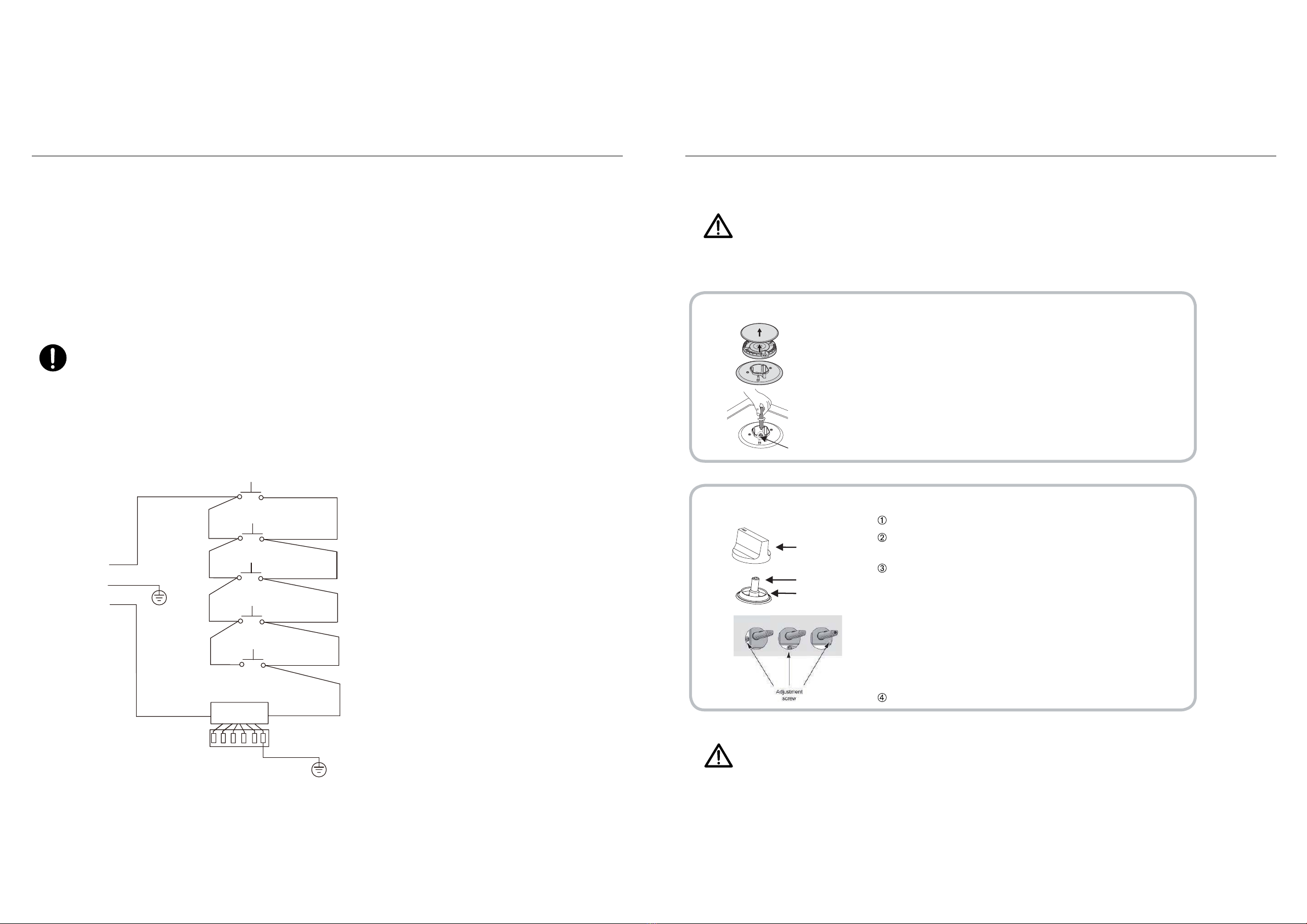
Gas adjustment
1
2
Injector
Control handle
Tap
Sealing ring
23
Remove the pan support, Burner lid and Flame spreader.
Unscrew the injector using a 7mm box spanner and
replace it with the stipulated injector for new gas
supply. Carefully reassemble the all components.
After injectors are replaced, it is advisable to strongly
tighten the injector in place.
Adjustment of minimum level of the flame.
Turn the taps down to minimum.
-
Remove the knob from the tap and place a small
bladed screwdriver in the centre of the tap shaft.
The correct adjustment is obtained when the flame
has a length of about 3 - 4 mm.
-
For butane
/ propane gas, the adjusting screw must
Make sure that the flame does not go out by
quickly turning from maximum flow to minimum
flow. If it does then remove the control knob and
make further adjustments to the gas flow, testing it
again once the adjustment has been made.
Repeat this process for each one of the gas taps.
be tightly screwed in.
Refit the control knob.
Ŷ7DNHSUHFDXWLRQVRQWKHRSHUDWLRQVDQGDGMXVWPHQWVWREHFDUULHGRXWZKHQ
FRQYHUWLQJIURPRQHJDVWRDQRWKHU
Ŷ$OOZRUNPXVWEHFDUULHGRXWE\DTXDOL¿HGWHFKQLFLDQ
Ŷ%HIRUH\RXEHJLQWXUQRIIWKHJDVDQGHOHFWULFLW\VXSSO\WRWKHDSSOLDQFH
-
Ŷ
%HIRUHSODFLQJWKHEXUQHUV
EDFNRQWKHWRSSODFHPDNHVXUH
WKDWWKHLQMHFWRULV
QRWEORFNHG
FDUULHGRXWDIWHUJDVFRQYHUVLRQ
VXFKDVVRDSZDWHURUJDV
DTXDOL¿HGWHFKQLFLDQRULQVWDOOHU
KDVWRPDUN³9´RQWKHULJKWJDV
FDWHJRU\
WRPDWFKZLWKWKH
VHWWLQJ
LQUDWLQJSODWH
5HPRYHWKHSUHYLRXV
VHWWLQJ³9´PDUN
LQWKHHYHQWRIDPDOIXQFWLRQ
FKDQJHWKHZKROHWDS
Ŷ
$IXOORSHUDWLRQDOWHVWDQGDWHVW
IRUSRVVLEOHOHDNDJHVPXVWEH
Ŷ
$IWHUFRPSOHWLQJFRQYHUVLRQ
GHWHFWRU
Change the injector of the burners.
ŶDo not dismantle the tap shafe:
24
Installation
Electrical Connection
- Green/yellow = Earth
- Blue = Neutral
- Brown = Live
22
■ This appliance is designed to be connected to a 220-240V, 50Hz-60Hz AC electricity supply.
Ŷ7KHZLUHZKLFKLVFRORXUHGJUHHQDQG\HOORZPXVWEHFRQQHFWHG
WRWKHWHUPLQDOZKLFKLVPDUNHGZLWKWKHOHWWHU(RUE\WKHHDUWK
V\PERO
Ŷ7KHZLUHVLQWKHPDLQVOHDGDUHFRORXUHGLQDFFRUGDQFHZLWKWKHIROORZLQJFRGH
Wiring Diagrams
Switch 1
Switch 2
AC INPUT
Switch 3
Switch 4
IGNITION
L
E
N
Switch 5
-
When the power cord is damaged it must be replaced by the manufacturer to produce,
customer service agent or similarly qualified personnel.
23
Ŷ7KLVDSSOLDQFHPXVWEHHDUWKHG

26 27
Troubleshooting
Trouble shooting
Not ignited
No Spark. Check the electricity supply.
Badly ignited
The gas supply is closed.
The ignition plug is contaminated
with alien substance.
Noise made when
combusted and ignited
Flame goes out
when in use.
Yellow Flame
Different gas is used. Check the gas used.
Unstable Flame
Gas Smell
Wipe alien substance with a
dry cloth.
Gas leakage Stop using the product and
close the middle valve.Open
the window to ventilate.
Contact our service centre by
using a phone outside.
24
Repairs should be performed by a licensed technician only.Improper repair may result in
considerable danger to you and others.
The burner lid is badly assembled. Assemble the lid correctly.
The gas supply is not completely
open.
Open the gas supply
completely.
The burners are wet. Dry the burners lids carefully.
The holes in the flame spreader
are clogged. Clean the flame spreader.
The burner lid is badly assembled. Assemble the burner lid
correctly.
The flame supervision device is
contaminated with alien substance.
Open the gas supply
completely.
The burner lid is badly assembled. Assemble the lid correctly.
Clean the flame supervision
device.
Product being cooked has boiled
over and extinguished the flame.
Turn off burner knob.Wait one
minute and reignite zone.
A strong draught may have blown
the flame out.
Please turn off zone and check
cooking area for draught such
as open windows.Wait one
minute and reignite zone
The holes in the flame spreader
are clogged. Clean the flame spreader.
The burner lid is badly assembled. Assemble the burner lid
correctly.
Ŷ+RZHYHUVRPHPLQRUSUREOHPVFDQEHUHVROYHGDVIROORZV
Problem Probable cause Solution
Ŷ,ISUREOHPLVQRWVROYHGSOHDVHFRQWDFWFXVWRPHUFDUH centre.
For future reference, please record the following information which can be found on the rating plate and the date of
purchase which can be found on your sales invoice.
STORE DETAILS
STORE NAME
|
ADDRESS
|
TELEPHONE
|
PURCHASE DATE
|
PRODUCT DETAILS
MODEL NO.
|
SERIAL NO.*
|
Purchase Details
to this page
Attach your receipt

28 29
AUSTRALIAN WARRANTY TERMS & CONDITIONS
APPLIANCES
This document sets out the terms and conditions of the
product warranties for Residentia Group Appliances. It is
an important document. Please keep it with your proof of
purchase documents in a safe place for future reference
should you require service for your Appliance.
1. IN THIS WARRANTY
(a) ‘acceptable quality’ as referred to in clause 10 of this
warranty has the same meaning referred to in the
ACL;
(b) ‘ACL’ means Trade Practices Amendment (Australian
Consumer Law) Act (No.2) 2010;
(c) ‘Appliance’ means any Residentia Group product
purchased by you accompanied by this document;
(d) ‘ASR’ means Residentia Group authorised service
representative;
(e) ‘Residentia Group’ means Residentia Group Pty Ltd of
165 Barkly Avenue Burnley VIC, ACN 600 546 656 in
respect of Appliances purchased in Australia;
(f ) ‘major failure’ as referred to in clause 10 of this
warranty has the same meaning referred to in the ACL
and includes a situation when an Appliance cannot
be repaired or it is uneconomic for Residentia Group,
at its discretion, to repair an Appliance during the
Warranty Period;
(g) ‘Warranty Period’ means:
(i) where the Appliance is used for personal,
domestic or household use (i.e. normal
single family use) as set out in the instruction
manual, the Appliance is warranted against
manufacturing defects for 36 months,
following the date of original purchase of
the Appliance;
(h) ‘you’ means the purchaser of the Appliance not
having purchased the Appliance for re-sale, and
‘your’ has a corresponding meaning.
2. This warranty only applies to Appliances purchased
and used in Australia and is in addition to (and does
not exclude, restrict, or modify in any way) any
non-excludable statutory warranties in Australia.
3. During the Warranty Period Residentia Group or its
ASR will, at no extra charge if your Appliance is readily
accessible for service, without special equipment
and subject to these terms and conditions, repair or
replace any parts which it considers to be defective.
Residentia Group or its ASR may use remanufactured
parts to repair your Appliance. You agree that any
replaced Appliances or parts become the property
of Residentia Group. This warranty does not apply
to light globes, batteries, filters or similar perishable
parts.
4. Parts and Appliances not supplied by Residentia
Group are not covered by this warranty.
5. You will bear the cost of transportation, travel and
delivery of the Appliance to and from Residentia
Group or its ASR. If you reside outside of the service
area, you will bear the cost of:
(a) travel of an authorised representative;
(b) transportation and delivery of the Appliance to and
from Residentia Group or its ASR, in all instances,
unless the Appliance is transported by Residentia
Group or its ASR, the Appliance is transported at
the owner’s cost and risk while in transit to and from
Residentia Group or its ASR.
6. Proof of purchase is required before you can make a
claim under this warranty.
7. You may not make a claim under this warranty unless
the defect claimed is due to faulty or defective parts
or workmanship. Residentia Group is not liable in the
following situations (which are not exhaustive):
(a) the Appliance is damaged by:
(i) accident
(ii) misuse or abuse, including failure to properly
maintain or service
(iii) normal wear and tear
(iv) power surges, electrical storm damage or
incorrect power supply
(v) incomplete or improper installation
(vi) incorrect, improper or inappropriate operation
(vii) insect or vermin infestation
(viii) failure to comply with any additional instructions
supplied with the Appliance;
(b) the Appliance is modified without authority from
Residentia Group in writing;
(c) the Appliance’s serial number or warranty seal has
been removed or defaced;
(d) the Appliance was serviced or repaired by anyone other
than Residentia Group, an authorised repairer or ASR.
8. This warranty, the contract to which it relates and the
relationship between you and Residentia Group are
governed by the law applicable where the Appliance
was purchased.
9. To the extent permitted by law, Residentia Group
excludes all warranties and liabilities (other than as
contained in this document) including liability for any
loss or damage whether direct or indirect arising from
your purchase, use or non use of the Appliance.
10. For Appliances and services provided by Residentia
Group in Australia, the Appliances come with a
guarantee by Residentia Group that cannot be
excluded under the Australian Consumer Law. You
are entitled to a replacement or refund for a major
failure and for compensation for any other reasonably
foreseeable loss or damage. You are also entitled
to have the Appliance repaired or replaced if the
Appliance fails to be of acceptable quality and the
failure does not amount to a major failure. The benefits
to you given by this warranty are in addition to your
other rights and remedies under a law in relation to the
Appliances or services to which the warranty relates.
11. At all times during the Warranty Period, Residentia
Group shall, at its discretion, determine whether repair,
replacement or refund will apply if an Appliance has a
valid warranty claim applicable to it.
12. To enquire about claiming under this warranty, please
follow these steps:
(a) carefully check the operating instructions, user manual
and the terms of this warranty;
(b) have the model and serial number of the Appliance
available;
(c) have the proof of purchase (e.g. an invoice) available;
(d) telephone the numbers shown below.
13. You accept that if you make a warranty claim,
Residentia Group and its ASR may exchange
information in relation to you to enable Residentia
Group to meet its obligations under this warranty.
IMPORTANT
Before calling for service, please ensure that the steps in
point 12 have been followed.
Telephone contact
► Service: Please call 1300 11 HELP (4357)
The Australian Consumer Law requires the inclusion of the following statement with this warranty:
Our goods come with guarantees that cannot be excluded under the Australian Consumer Law. You are entitled to a
replacement or refund for a major failure and for compensation for any other reasonably foreseeable loss or damage.
You are also entitled to have the goods repaired or replaced if the goods fail to be of acceptable quality and the failure
does not amount to a major failure.
Warranty Information

30 31
NEW ZEALAND WARRANTY TERMS & CONDITIONS
APPLIANCES
To help care for your investment, be sure to register your
appliance online. Registration will help you if you need to
arrange service in the future, and serves as a record of
your purchase – including critical information like model
number and serial number – that you can refer to at any
time.
Simply visit the below website, or ask your retailer
for help:
https://inalto.house/nz/registration
WARRANTY:
These products are covered by a warranty for a period
of 24 months from the date of purchase, subject to the
following conditions*. The warranty covers rectification
free of charge of any fault arising from defective materials
or components, or faulty workmanship or assembly.
* The conditions above mentioned are:
1. That the purchaser carefully follows all instructions
packed with the product;
2. That the purchaser and/or installer carefully follows
the installation instructions provided and complies
with electrical wiring regulations, gas and/or
plumbing codes;
3. That the purchaser carefully follows instructions
provided in the owner’s handbook relating to the
proper use and care of the product and does not use
the product for any purpose other than the domestic
use for which it has been designed;
4. Commercial use of the product for professional or
industrial purposes will void this warranty.;
5. That the product was purchased and installed in New
Zealand;
6. That this warranty does not extend to:
a) optional glass lids for hobs apart from claims
which relate to mechanical or physical damage
thereof at the date of purchase;
b) ‘consumable’ parts such as light bulbs or
filters;
c) damage to ceramic glass caused by liquid
or solid spill-overs, lack of maintenance,
or impact;
d) damage to surface coatings caused by
cleaning or maintenance using products not
recommended by the owner’s handbook;
e) defects caused by normal wear and tear,
accident, negligence, alteration, misuse or
incorrect installations;
f) a product dismantled, repaired or serviced by
any serviceman other than an authorised service
agent;
g) a product not in possession of the original
purchaser;
h) damage caused by power outages or surges
i) damage caused by pests (eg. rats, cockroaches
etc.)
7. That if the product is a freestanding microwave
oven or small appliance it must be returned to the
dealer/ retailer for servicing. These products, unless
stated otherwise, have a 12 month warranty from
original date of purchase with 24 months on the
microwave magnetron; Waste disposers have a 12
month warranty.
8. The provision of service under this warranty is
limited by a 25km boundary from the retailer where
the product was purchased except for microwaves.
Such travelling outside of these limits will incur
commercial cost to be paid by you, regulated by the
number of kilometres travelled beyond the 25km limit
(50km return trip). Microwaves are to be delivered
to the nearest authorised service agent by the
customer.
Please refer to your user manual for any further conditions
that may apply to your specific model.
Nothing herein contained shall be construed in any way
as excluding or limiting your rights under the Consumer
Guarantees Acts 1993.
For Service please visit www.applico.co.nz/service or
contact the dealer/retailer from whom you purchased the
product from or call the 0800 number listed below. If you
are unable to establish the date of purchase, or the fault is
not covered by this warranty, or if the product is found to
be in working order, you will be required to bear all service
call charges.
Registration of this warranty constitutes acceptance of the
terms and conditions of this warranty.
Should you require any assistance, please call Customer
Services on 0800 763 448.
Distributed by Applico Ltd.
www.applico.co.nz
July 2019
After registering your appliance online, we recommend
you fill out the below information for your reference and
keep this warranty card in a
safe place.
THIS WARRANTY IS VALID IN NEW ZEALAND ONLY.
This page
is intentionally
left blank

A HIGHER LEVEL OF COOKING
—
WWW.INALTO.HOUSE
—
Table of contents
Other Inalto Cooktop manuals

Inalto
Inalto ICC604K.1 User manual

Inalto
Inalto ICC302K User manual

Inalto
Inalto ICC302K.1 User manual

Inalto
Inalto ICG905W User manual

Inalto
Inalto ICI30T.1 User manual

Inalto
Inalto IE62T User manual

Inalto
Inalto Esatto EE60T User manual

Inalto
Inalto ICGW71 User manual

Inalto
Inalto ICC604K User manual

Inalto
Inalto ICI302K.1 User manual

Inalto
Inalto ICGG604W User manual

Inalto
Inalto ICC604TB.1 User manual

Inalto
Inalto ICI30T.1 User manual

Inalto
Inalto ICC302K.1 User manual

Inalto
Inalto ICC60T User manual

Inalto
Inalto ICI603K.1 User manual

Inalto
Inalto ICGG302W User manual

Inalto
Inalto IE60T User manual

Inalto
Inalto IE92T User manual

Inalto
Inalto II65T User manual


