Inax SATIS DV-218-VH-W User manual

PCW-1115-W(08100)
Installation Manual
DV-218-VH-W (GBC-941SU-AY)
●Use an receptacle with a maximum rating of AC 220 V and 1200 W.
●The length of the power cord is 1.2 m.
Install the receptacle so that it is within reach of the power cord and high enough from the oor so that water won't splash on it.
●Be sure to install a ground (Class 3 ground terminal construction).
* Ask an electrical contractor to install the wiring.
* Do not insert the power plug in the receptacle until installation is completely nished.
Doing so may cause system failure.
Power Supply
●
Be sure to connect the water supply parts to the potable water line.
If surface water, industrial water or well water is used, it may cause
deterioration of electrical and mechanical parts and lead to accidents.
Water Supply
Water Pressure
●The minimum operating water pressure when 20 L/min. is
owing is 0.1 MPa {1.0 kgf/cm2} or greater. The maximum water
pressure is 0.75 MPa {7.5 kgf/cm2} under hydrostatic pressure.
Even if other xtures are used simultaneously, a supply water
pressure of 0.1 MPa {1.0 kgf/cm2} or greater and less than 0.75
MPa {7.5kgf/cm2} is required. If this minimum water pressure is
not reached, pressure will be insufcient to operate the product’s
cleaning functions.
●The amount of space required for this toilet is shown in the following diagram.
At least 400 mm of clear space is required in front of the toilet in order for the
open/close function of the non-touch toilet seat lid to operate correctly.
Minimum Installation Clearance
BE SURE TO FOLLOW
THESE PRECAUTIONS AND
INSTRUCTIONS
These safety precautions are essential for safe
installation and use of the product.
Please read the precautions thoroughly before
installing the product.
Explanation of Terms and Symbols
Absolutely do not allow anyone except
an authorized service technician to
disassemble, repair or modify this product.
*There is danger of electric shock, or re, causing injury.
DON'T
DISASSEMBLE
Do not use any power supply other
than AC 220 V. Do not use any
other method to connect the plug to
an improperly congured receptacle.
*Use of exceeding the rated voltage could cause re.
FORBIDDEN
Thoroughly insert the power plug to
the power point.
* Otherwise, it may cause re or electrify
the user.
OBSERVE
Lead water from a system that
provides drinkable water. If dirt or
impure substances clogs the strainer,
install a lter to the water inlet.
OBSERVE
Do not use a receptacle that is loose and
in which the plug does not t snugly.
*There is danger of electric shock or re.
FORBIDDEN
Do not install or leave the main
body or remote controller in a
constantly humid location or
location where water, liquid or
splash may affect them.
FORBIDDEN
Do not pull out or insert the power
plug with wet hands.
*There is danger of electric shock.
NO WET
HAND
Do not pour water or cleanser
inside or on the body and remote
control, or on the power plug.
*There is danger of electric shock or re.
DON'T POUR
WATER
●
When removing the strainers, be sure
to close the water shutoff valve.
●
When installing the strainers, tighten if
fully until the line is hidden by the body.
*Household articles may get wet if there is water leakage.
OBSERVE
Porcelain is breakable.
●
Before installation, make sure the toilet
bowl is not cracked or otherwise damaged.
●
When installation is completed, check the toilet to
make sure it has not been damaged during the
installation work.
*Damaged parts could cause injury or water
leakage and soaking in the bathroom.
OBSERVE
If freezing weather is anticipated
before handing the product to the
customer, keep the water drained out.
*Freeze damage may cause water leakage or
damage household articles.
OBSERVE
Be sure to adjust the water shutoff
valve and check for water leakage
after installation.
*Household articles may get wet if there is water leakage.
OBSERVE
Make sure that the earth wire is
properly xed.
*Otherwise it may electrify the user in case
of malfunction or a short circuit.
*Consult your electrician if there is no earth terminal
around the power point.
EARTH
Do not nick, damage, carve, bend unduly, pull
on, twist, bind or place heavy objects on top of
the power cord, or pinch it between two objects.
*The above could damage the electrical conductors
and cause electric shock or re.
FORBIDDEN
1050 or more
425
400 or more
(mm)
700 or
more
WARNING···
CAUTION ···
NOTE ···
Indicates a potentially hazardous situation which, if not avoided,
could result in death or serious injury.
Indicates a potentially hazardous situation which, if not avoided,
may result minor or moderate injury or in damage to other
property.
Indicates a potentially hazardous situation, if not avoided, may
result in damage to other product.
WARNING CAUTION

Fasten the supply water line securely so that there is no looseness.
* If it is loose, there is danger of water leakage.
Fasten the supply water line securely!
Manual Set
*The deodorizing cartridge has already
been installed in the product.
Toilet Seat (Body)
Side Panel (left) Side Panel (right)
Batteries (2)
Wood Screw
Plastic Anchor
Water Shutoff
Valve
Water Supply
Pipe
Hemispherical
Face Plate
Water Supply Hose
(400 mm)
Bracket
Remote Control
Unit
Parts Check (Make sure all the parts are included in the packing box.)
Clip
AY Bolts for
Mounting Parts
Washer
Mounting Base
Adjuster
(Contained in the bottom
of the toilet bowl)
Flange
Gasket
Flange Nut
Washer
T-bolt
Mounting Nut
Decorator Caps (Large)
Nut
Washer
AY Bolts for Anchoring the Toilet
Washer
Installation Pattern Paper
Toilet
Fixing Fastener
(pre-attached to the
toilet bowl)
Available on request
600mm Part No.:322-1050
800mm Part No.:322-1049
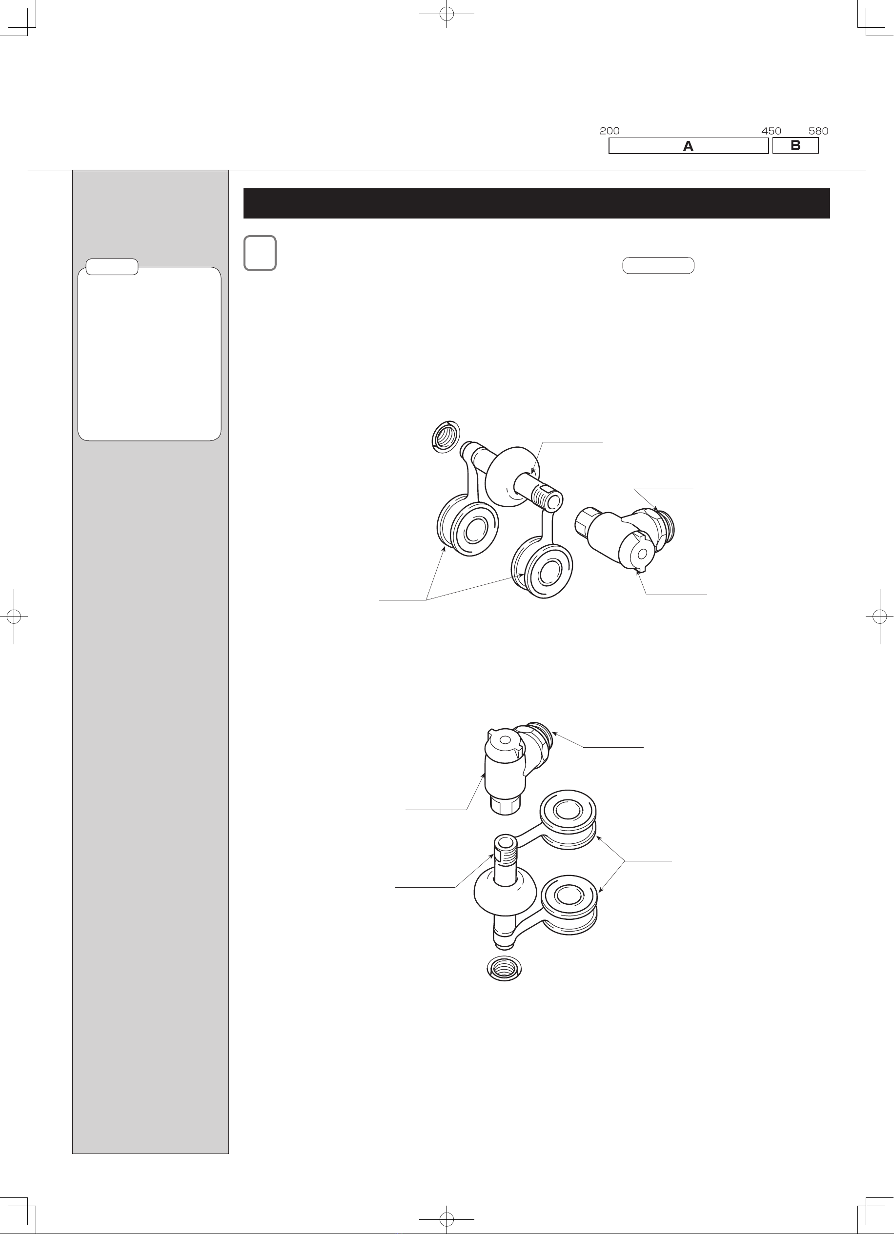
Names of Parts
Shower Strainer
Toilet Seat
Water
Shutoff Valve
Power Plug
Shutoff Valve
Flush Lever
Toilet Strainer
(See gure below.)
Body
Water Supply Hose
Toilet Lid
Remote Control Unit
Nozzle (for posterior)
Mounting Base
Nozzle (for bidet)
Shower Strainer
(See gure below.)
Toilet Strainer
Drain Socket
Adjuster
Flange
Rating Label
Caution
Label
To your bottom-right from the front of the body
●Carry out the construction in order beginning with the water shutoff
valve, then proceeding to the body.
●Make sure the distance to the
soil pipe is within a range of
200 and 580 mm. Match up
the adjuster with the distance
to the soil pipe, then cut it and
connect it securely using PVC
cement.
What is the distance to the soil pipe?
Positioning of water supply and drain pipes
Existing soil pipe
200 ~ 580
Adjuster
100
100
280
200~580
280
300 or more
330
Drain pipe
(VP100, VU100, VP75, or VU75)
Water supply 1/2B
(in case of supply from the wall)
Water supply 1/2B (in case of supply from the oor)
Remote
Control Unit
Light Receptor
If the remote control unit is
mounted on the left side wall
If it is necessary to mount the remote controller on the wall opposite to the remote controller receptor,
be sure to conrm that it can receive signals from the installation location before mounting it.
If there is a washstand or other object installed on the side where the remote controller receptor is
located and the remote controller needs to be mounted at a considerable distance from the toilet, the
Satis may not be able to pick up remote controller signals. In such a case, install a screen that can
reect the signals within 1300 mm from the center of the toilet.
*Please prepare the screen on site.
The screen should be at least 1100 mm high and be wide enough to reach the position where the
remote controller is mounted. (However, depending on the wall nish, color and other conditions, the
size of the screen may differ somewhat, so please check to determine the best size.)
As much as possible, install the remote controller on the wall on
the side where the remote controller receptor is located.
Remote Control Unit Mounting Location
If the remote control unit is
mounted on the right side wall
1300 mm or less
Screen
Light Receptor Remote
Control Unit
Installation
Installing the Water Shutoff Valve
After nishing the walls and oor, install the water supply pipe and water shutoff valve.
*When installing the water shutoff valve on the water supply pipe, wind some sealing material around the threads,
such as seal tape.
*Tighten the water shutoff valve fully using tools.
中水_止水栓床.eps
In the case of water supply from the oor
Water Shutoff
Valve
Seal Tape
Water Supply
Pipe
Water Supply
Outlet
中水_止水栓壁.eps
Seal Tape
In the case of water supply from the wall
Water Supply
Pipe
Water Supply
Outlet
Water Shutoff
Valve
Please note that the following installation steps 4 to 7 varies depending on the distance
between the wall and the centre of the soil pipe.
If the distance is between 200 and 450mm, go to section A.
If the distance is between 451 and 580mm, go to section B.
Distance between the wall and the centre of the soil pipe
See NOTE 1.
Do not get your hand
caught in the water shutoff
valve or step on it.
It could cause the pipe to
become unstable or damage
it, causing water leakage.
There is danger of marring
the wall or the oor.
Install the water supply
outlet in the proper direction
so that the water shutoff
valve won't cause bending
of the water supply hose.
●
*
*
●
NOTE 1
●Please read this installation manual carefully in order to install the product
correctly.
●Be sure to perform trial operation after installation.
●Be sure to hand this manual, User's Manual, and a warranty card to the customer.
Explain how to use the product when you hand it over to the customer.
NOTE
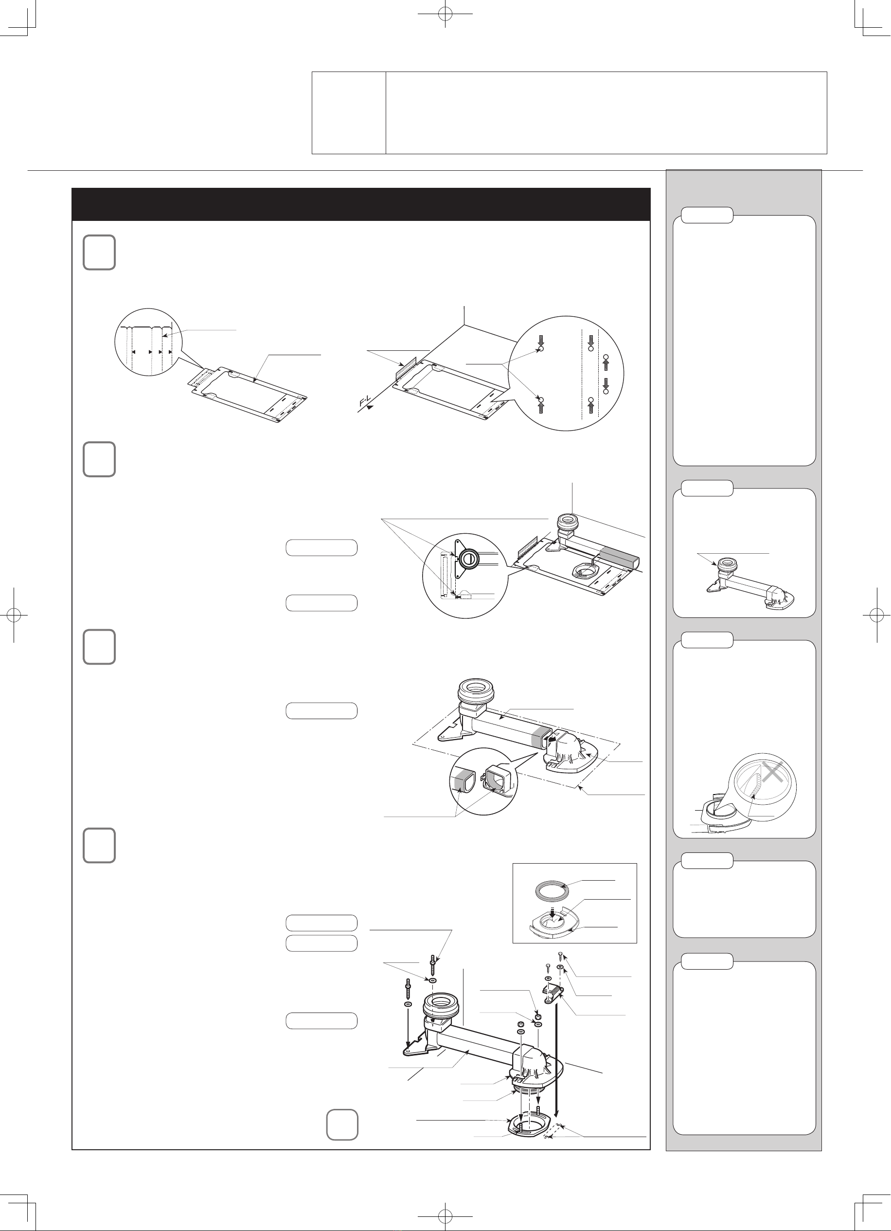
Positioning the Mounting Base
(1) Fold the installation pattern paper along
the perforated line "2".
5
5
1
2
3
4
1
2
3
4
1234
B
B
C
C
長さ合わせライン
アジャスター部 固定部材側
壁側
壁側
固定部材側
長さ合わせライン
アジャスター部
A
Perforated
Line "2"
Installation
Pattern Paper
(2) Touch the wall with the pattern paper and mark the C holes
(mounting holes for the mounting base) on the paper.
B
B
C
C
長さ合わせライン
アジャスター部 固定部材側
壁側
壁側
固定部材側
長さ合わせライン
アジャスター部
A
B
B
C
C
A
C Holes
Installation
Pattern Paper
Position the adjuster along the line as instructed "Position the rear
end of the drain socket along this line when you cut the drain adjuster"
on the pattern paper as shown in the diagram on the right. Cut the
adjuster in the centre of the ange that has been already xed.
See NOTE 2.
*If you make a longer cut on the adjuster, the toilet bowl will be positioned
closer to the wall. In that case, interference may occur between the
functioning parts and the wall, which prevents the installation.
See NOTE 3.
Cutting the Drain Adjuster
B
B
C
C
長さ合わせライン
アジャスター部 固定部材側
壁側
壁側
固定部材側
長さ合わせライン
アジャスター部
A
長さ合わせライン
アジャスター部
長さ合わせライン
アジャスター部
便器及び排水の仕様によりミシン目の折り位置が異なります。
施工説明書をご確認の上、正しく施工を行ってください。
壁側
壁側
Position the rear end of the drain
socket along this line when you cut
the drain adjuster.
排水ソケットガスケット取付.eps
Marked Holes
AY Bolts for
Anchoring the Toilet
Drain Adjuster
Gasket
Drain Outlet
Flange
Washer
Flange
Gasket
Existing Flange
T Bolt
Fixing Part
Washer
AY bolts for the
mounting base
Washer
Flange Nut
06M038 ソケット接着.eps
Drain Adjuster
Level Surface
Flange
Insertion Margin
Bonding the Drain Adjuster with the Flange
Apply adhesive agent on the contacting parts of the
drain adjuster and the ange and connect them.
See NOTE 4.
Fixing the Drain Adjuster, Flange and Mounting Base
(1) Mount the gasket to the draining outlet of the
ange and x them on the existing ange with
washers and ange nuts.
See NOTE 5.
See NOTE 6.
(2) Fix the drain socket with washers and the AY
bolts for xing a toilet bowl.
Drill prepared holes (dia 11, depth 55) and use
the AY bolts.
See NOTE 6.
(3) Align the mounting base with the marked spots
and x it with the AY bolts for the mounting base.
Drill prepared holes (dia 11, depth 55) and use
the AY bolts.
to
Distance between the wall and the centre of the soil pipe: 200 - 450mm
When you x the drain socket
on the oor, make sure that
the oor is not sloping or
uneven. If the drain adjuster
is xed on an inverse slope,
it may cause ushing
malfunction or clogging.
When you x the socket with
ange nuts, make sure not to
clench them too much.
Otherwise it may damage
the ange, which may cause
water leakage.
●
●
*
NOTE 6
If the existing bolts and
nuts, etc. on the ange are
corroded, use the T-bolts,
ange nuts, and washers
provided with the Satis.
●
NOTE 5
Never drop the drain
adjuster or ange on the
oor by mistake.
It may cause water leakage
from the damaged part.
After cutting the adjuster,
insert it into the ange
tentatively to see if the
adjuster length is correct.
Insufcient insertion will
cause the toilet installation
position to shift, resulting in
defective work.
Vertically cut the adjuster.
If it is cut askew, it may cause
water or odour leakage.
Do not leave burr on the
adjuster after cutting it.
It may case water or leakage.
●
*
●
*
●
*
●
*
NOTE 2
Make sure the adjuster and
ange are properly bonded.
Look in the bottom of the
ange and check if the adjuster
is thoroughly inserted.
If they are not adequately
bonded, it may cause water
or odour leakage.
●
*
NOTE 4
Gap
If you wrongly cut or bond
the adjuster, order the
following part number.
●
NOTE 3
CF-340SG-SET

Distance between the wall and the centre of the soil pipe: 451 - 580mm
Cutting the Drain Adjuster
Cut the drain adjuster for 100mm as shown in the
diagram on the right.
*If you make a longer cut on the adjuster, the toilet
bowl will be positioned closer to the wall. In that case,
interference may occur between the functioning parts
and the wall, which prevents the installation.
See NOTE 2.
06M038 アジャスター切断(d).eps
100mm
Bonding the Drain Adjuster with the Flange
Apply adhesive agent on the contacting parts of the
drain adjuster and the ange and connect them.
When connecting the drain socket with the adjuster,
t the concave part with the convex part.
See NOTE 3. See NOTE 4.
06M038 ソケット接着.eps
Drain Adjuster
Level Surface
Flange
Insertion
Margin
Fixing the Drain Adjuster and Flange
(1) Mount the gasket to the draining outlet of the
ange and x them on the existing ange with
washers and ange nuts.
See NOTE 5. See NOTE 6.
(2) Fix the drain socket with washers and the AY
bolts for xing a toilet bowl.
Drill prepared holes (dia 11, depth 55) and use
the AY bolts.
Align the installation pattern paper with the rear end
of the drain adjuster and mark the C holes (mounting
holes for the mounting base) on the pattern paper.
Drill prepared holes (dia 11, depth 55) and use AY
bolts.
Fixing the Mounting Base
C穴
C穴
E穴
E穴
長さ合わせライン
アジャスター部 固定部材側
壁側
壁側
固定部材側
長さ合わせライン
アジャスター部
B穴
A穴
B
B
C
C
A
便器及び排水の仕様によりミシン目の折り位置が異なります。
施工説明書をご確認の上、正しく施工を行ってください。
壁側
壁側
Fixing Part
Washer
C Holes
AY Bolts for Anchoring the Toilet
to
フランジ部固定.eps
Existing Flange
Flange
Gasket
AY Bolts for Anchoring the Toilet
Washer
Flange Nut
Washer
Drain Adjuster
排水ソケットガスケット取付.eps
Gasket
Drain Outlet
Flange
When you x the drain socket
on the oor, make sure that
the oor is not sloping or
uneven. If the drain adjuster
is xed on an inverse slope,
it may cause ushing
malfunction or clogging.
When you x the socket with
ange nuts, make sure not to
clench them too much.
Otherwise it may damage
the ange, which may cause
water leakage.
●
●
*
NOTE 6
If the existing bolts and
nuts, etc. on the ange are
corroded, use the T-bolts,
ange nuts, and washers
provided with the Satis.
●
NOTE 5
Never drop the drain
adjuster or ange on the
oor by mistake.
It may cause water leakage
from the damaged part.
After cutting the adjuster,
insert it into the ange
tentatively to see if the
adjuster length is correct.
Insufcient insertion will
cause the toilet installation
position to shift, resulting in
defective work.
Vertically cut the adjuster.
If it is cut askew, it may cause
water or odour leakage.
Do not leave burr on the
adjuster after cutting it.
It may case water or leakage.
●
*
●
*
●
*
●
*
NOTE 2
Make sure the adjuster and
ange are properly bonded.
Look in the bottom of the
ange and check if the adjuster
is thoroughly inserted.
If they are not adequately
bonded, it may cause water
or odour leakage.
●
*
NOTE 4
Gap
If you wrongly cut or bond
the adjuster, order the
following part number.
●
NOTE 3
CF-340SG-SET
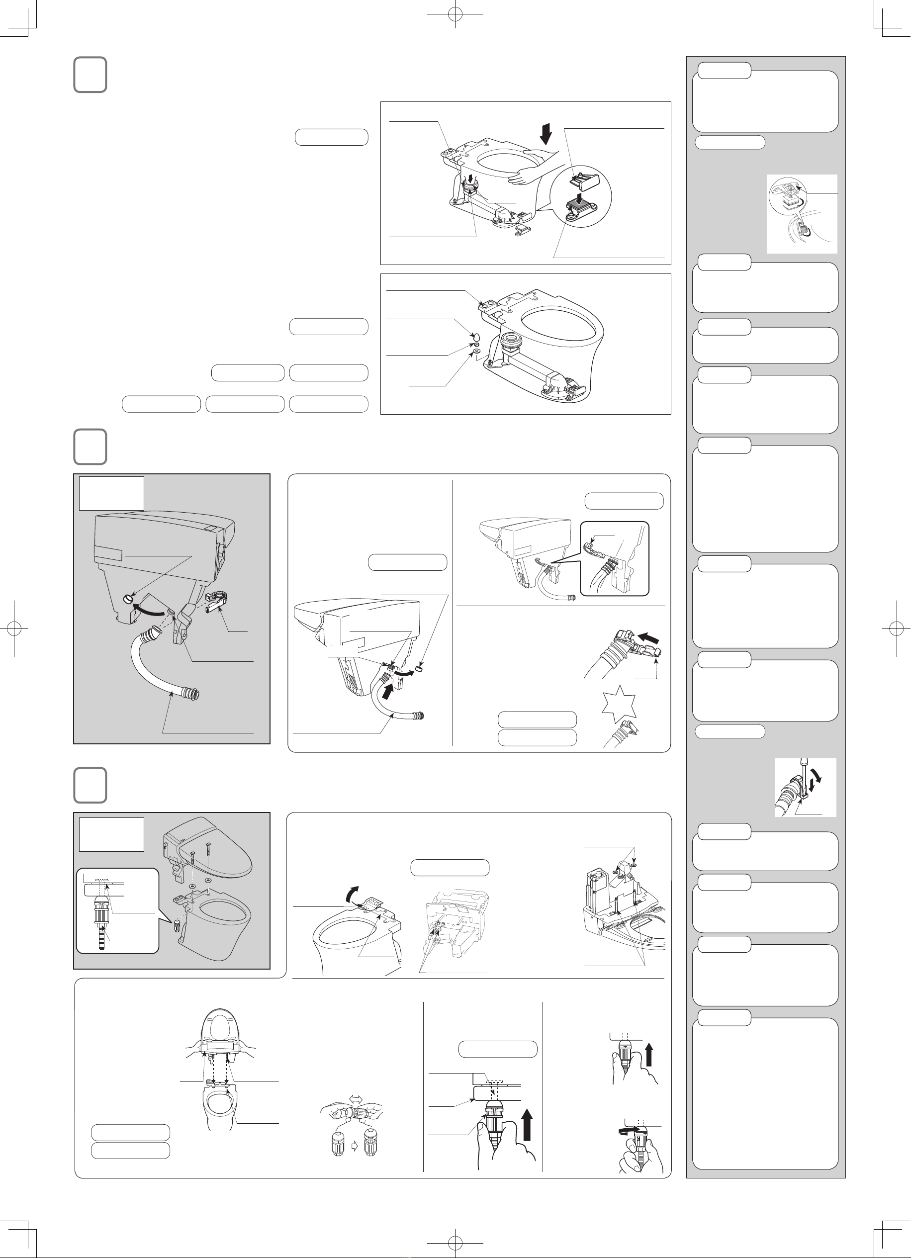
Installing the Water Supply Hose (Body Side)
ホース取付(本体).eps
Installation
Diagram
Water Supply
Inlet on Body
Install the water
supply hose
in a direction
so that it is
not bent when
connected.
Clip
Protective Cap
Water Supply Hose
(3) Fit the clip over the end of the water supply hose and the
body water supply inlet securely.
See NOTE 12.
(1) Remove the protective cap from
the body water supply inlet.
(2) Insert the end of the water
supply hose in the water supply
inlet of the body.
See NOTE 11.
(4) Bend the clip around and
fasten the water supply hose
and the body water supply
inlet securely together with it.
After installation, turn the
clip's open portion so it ts in
and locks together with the
other end.
See NOTE 13.
See Reference 2.
Click
Clip
Bend the clip around.
Click
ホース取付2.eps
Clip
Protective Cap
O-ring
Water Supply
Inlet on Body
Water Supply Hose
Mounting the Toilet Bowl
(1) Insert the drain pipe of the toilet bowl in the rubber drain socket joint,
then position thetoilet bowl with the front end raised up and loose.
See NOTE 7.
(2) Slowly put down the front of the toilet bowl. Fit the xing fasteners of
the mounting base and toilet bowl.
(3) Lower the front end of the toilet bowl until the clicking sound stops.
This operation applies pressure to the mounting fastener. Continue to
push down on the front end of the toilet bowl until the clicking sound stops
and the toilet bowl is in contact with the oor.
(4) Swing the toilet bowl lightly to make sure the front end is fastened
securely to the oor.
If the toilet bowl is not fastened securely, remove it, loosen the
T-bolts of the mountin gfastener in the oor about 5 turns, then
repeat the installation procedure.
If positioning of the toilet deviates from the correct position, lift up
the front end of thetoilet bowl, position it again and push the toilet
down in that position to fasten it again.
See Reference 1.
(5) Fasten the rear end of the toilet bowl using the washers and mounting
nuts supplied, and then install the decorator caps.
See NOTE 7.
See NOTE 8.
*When reinstalling the toilet bowl
See NOTE 9.
See NOTE 10.
See Reference 1.
*
*
*
06M038 化粧キャップ付ける.eps
Decorator Cap
Flush Water Inlet
Mounting Nut
Washer
Installing the Body
2. Install the at packings.
Install the at
packings on
the 2 mounting
bolts on the
bottom of the
body.
Install the at
packings so
that the body
cover does not
get any aw.
*
パッキン取付1.eps
Mounting Bolt
Flat Packing
3. Install the body on the toilet.
Place the
mounting bolts
on the bottom
of the body in
the 2 mounting
holes in the
back of the
toilet bowl to
install the body.
See NOTE 15.
See NOTE 16.
タンク取付2.eps
Mounting Hole
Mounting Bolt
Body
4. Fasten the body.
(1) Make sure the
mounting nuts are
open.
If they are closed, pull
on them as shown
until they click.
Cナット開く.eps
Closed State Open State
(2) Place the new
mounting nuts on
the mounting bolts.
See NOTE 17.
Cナット通す.eps
Toilet
Bowl
Mounting Bolt
Mounting
Nut
(3) Push up on the
new mounting nuts
to close
them.
(4) Turn the new
mounting nuts by
hand to
tighten
them.
Mounting Fastener
(Mounted on the toilet bowl)
Drain Pipe
Rubber Drain Joint
Insert
Push Down
Fixing fastener
(on the mounting base)
Installation
Diagram
Flat Packing
New Mounting Nut
1. Remove the protective tape and protective cap.
Remove the protective tape from the toilet bowl,
and then remove the protective cap from the body.
See NOTE 14.
施工時~1.eps
<Body>
Protective Cap
施工時2.eps
<Toilet Bowl>
Protective Tape
Plate
(metal)
Cナット押込.eps
Push up.
Cナット締付.eps
Tighten
Do not place the toilet bowl on
the pedestal or drain socket.
Otherwise it may damage the socket or packing
gland, which may cause water leakage.
*
NOTE 7
Do not tighten the screws
tootightly against the ceramic.
There is danger of the ceramiccracking.
*
NOTE 8
Avoid damaging or allowing foreign
matter to enter the ush water inlet.
NOTE 9
Reference 1
1) Remove decorator caps, mounting nuts and
washers from the rear of the toilet bowl.
2) Raise the toilet bowl
up slowly.
3) Loosen the T-bolts in
the fastener at the rear
of the toilet bowl about
5 turns, then mount
the toilet once again.
Tボルト調整.eps
T-bolts
Loosen them about 5 turns.
When removing the toilet bowl, be
careful not to damage the toilet
with the toilet bowl mounting
bolts in the rear of the toilet bowl.
NOTE 10
Be careful not to damage the O-ring.
Water may leak if the O-ring is broken or damaged.
Remove the cap on the water supply
hose immediately before connecting
it to the water shutoff valve.
There is danger of dirt, etc. getting inside the
water supply hose while the work is proceeding,
making it difcult to shut off the ow of water.
●
*
●
*
NOTE 11
Thoroughly insert the clip on
the front or from the back.
If it is tted at a slant, the clip may become bent out
of shape and might not fasten the hose securely.
Fit the clip securely.
If it does not t tightly, there could be water leakage.
●
*
●
*
NOTE 12
Fit the ends of the clip together,
engaging them until a click
sound is heard.
If the clip does not t tightly, there could be water leakage.
*
NOTE 13
Do not remove the (metal) plate.
There is danger of water leakage.
*
NOTE 14
Do not take hold of the ush
handle to lift the body.
The body or the ush handle could become damaged.
*
NOTE 15
Make sure the body is sitting
rmly on the toilet bowl.
There is danger of water leaking from the water inlet to
the toilet if the body is not seated rmly on the toilet.
*
NOTE 16
Tighten the mounting nuts gradually,
alternating the tightening between
the left and right sides to keep from
putting too much strain on one side.
Uneven tightening could cause water leakage.
The black rubber portion of the
new mounting nuts is the top.
Screw the nuts on in the direction
indicated by the arrow mark.
If it is difcult to tighten the nuts
by hand, tighten them further
using a 17 mm wrench.
●
*
●
●
NOTE 17
Reference 2
When removing the clip, hold
the clip with your
ngers and insert
the at-blade
screwdriver. Then,
push it downward
as shown right.
●
クリップ外す.eps
Push
Clip
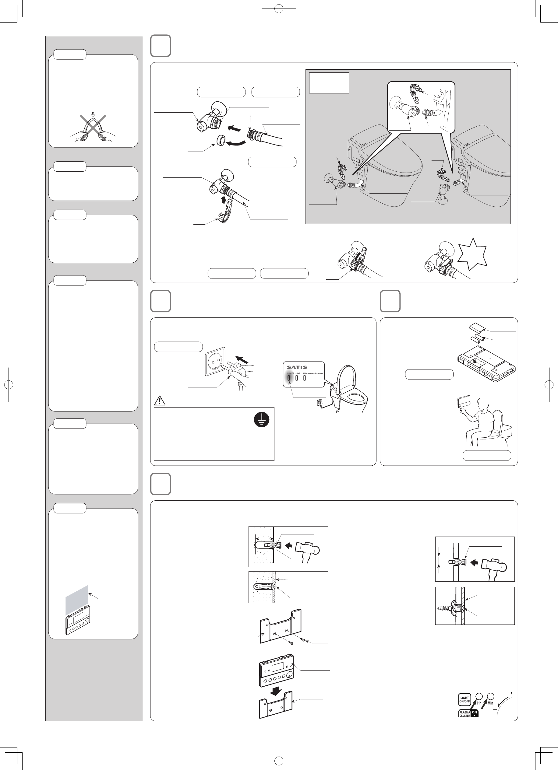
Mounting the Remote Control
(1) Place the bracket on the wall depending on the wall material as follows, then mount it in the desired mounting position.
If mounted either in plywood paneling 5 mm
or less in thickness or in gypsum board:
A) In plywood paneling, drill
holes with a diameter of 6
mm; in gypsum board, drill
holes with a diameter of 5
mm.
B) Using a hammer, gently
drive the plastic anchors
into the holes.
C) Fasten the bracket securely
to the anchors using wood
screws. As you tighten the
screws, they are hard to turn at rst, then gradually
get easier to turn, and then are hard to turn again.
Bracket
Wood Screw
Plastic Anchor
6 mm
dia.
(2) Align the remote control
unit with the bracket and
then push it down onto the
bracket.
Remote
Control Unit
Bracket
Installing the Water Supply Hose (Water shutoff valve side)
In the case of
water supply
from the wall
In the case of
water supply
from the oor
Clip Clip
Water
Shutoff Valve
Water
Shutoff Valve
Water
Shutoff Valve
Water Supply Hose Water Supply Hose
O-ring
Clip
(1) Remove the cap from the end of the water supply hose, then
insert it in the water supply outlet of the water shutoff valve.
See NOTE 11. See NOTE 18.
(2) Fasten the clip securely. See NOTE 19.
本体ホース付け5.eps
O-ring
Water Supply Hose
Water Supply Outlet
Water Shutoff Valve
Cap
(3) Install the clip in the same way as on the
body supply water inlet side, making sure
the two sides of the clip t securely and lock
together.
See NOTE 20.
See Reference 1.
クリップ付ける2.eps
カチッ
Click
Clip
Bend the clip
around.
クリップ付ける.eps
Water Supply Hose
Clip
Water Shutoff Valve
(3) Open the remote control unit's lower half to expose the
additional controls. Press and hold the "Hr" button, and
release the button when the current hour is shown.
Make sure AM or PM appears, as appropriate.
Repeat this procedure with the
"Min" button to set the current
minute.
Connecting the Power Supply
1. Insert the power plug in
the receptacle.
See NOTE 21.
2. Conrm that the system
has been turned on.
Conrm that the power
lamp on the body is lit.
If the power lamp of the body does
not light up, press the reset button
on the power plug and make sure
the lamp lights up in green.
Wait for around 10 seconds before
inserting the power plug again.
*
*
プラグ差し込み.eps
Power Plug
Power Lamp
Connect the product to a
properly grounded outlet only.
There is danger of electric shock if a
breakdown or current leakage occurs.
When a three-slot receptacle is
needed, contact a licenced electrician.
*
*
EARTH
WARNING
(1) Open the back
cover of the remote
control unit and
insert the batteries
(two AA size
batteries).
See NOTE 22.
(2) Place the remote
control unit in the
position you would
like it to be in, sit
down on the toilet
seat and press the
stop switch. If you
hear an electronic
"beep" sound from
the body.
Positioning the
Remote Control Unit
If mounted in concrete or on block bed:
A) Drill holes with a diameter
of 6 mm and a depth of
approximately 33 mm .
B) Using a hammer, gently drive
the plastic anchors into the
holes.
C) Fasten the bracket securely
to the anchors using wood
screws.
If mounted in plywood
paneling 5 mm or
greater in thickness:
Fasten the bracket to the
wall with the wood screws.
Battery
Back Cover
⊕
⊖
⊖
⊕
Installation
Diagram
Bracket
Wood Screw
Plastic Anchor
6 mm dia.
33 mm
Wood
Screw
Bracket
Fit the clip securely.
If it does not t tightly, there
could be water leakage.
*
NOTE 19
Fit the ends of the clip
together, engaging them
until a click sound is heard.
If it does not t tightly, there
could be water leakage.
*
NOTE 20
Do not bend the water supply
hose at a sharp angle.
There is danger of its becoming
damaged and leaking water.
It could also cause the toilet
not to ush properly.
*
NOTE 18
Be sure to turn on the power
only after installation of the
product is completed.
If the power plug does not light
up, press the reset button and
check to make sure the power
lamp lights up.
Do not insert the power plug in
the receptacle while touching
the toilet seat. The shower
nozzle (posterior, bidet) may
not extend if you do.
If the shower nozzle does not
extend, pull out the power plug,
then insert it again without
touching the toilet seat.
●
●
●
NOTE 21
Install the batteries with
the positive and negative
poles facing the correct
direction in accordance
with the marks on the
remote control unit case.
Do not use old and new
batteries together.
●
●
NOTE 22
Water will spray from the
nozzle if the Shower or
Bidet switch is pressed,
so exercise caution.
Check to make sure there
is enough space above the
remote controller to mount
or remove the controller at
its mounting position.
●
●
NOTE 23
Required
space
See NOTE 23.
PCW-1115-W(08100)
Installing the Side Panels
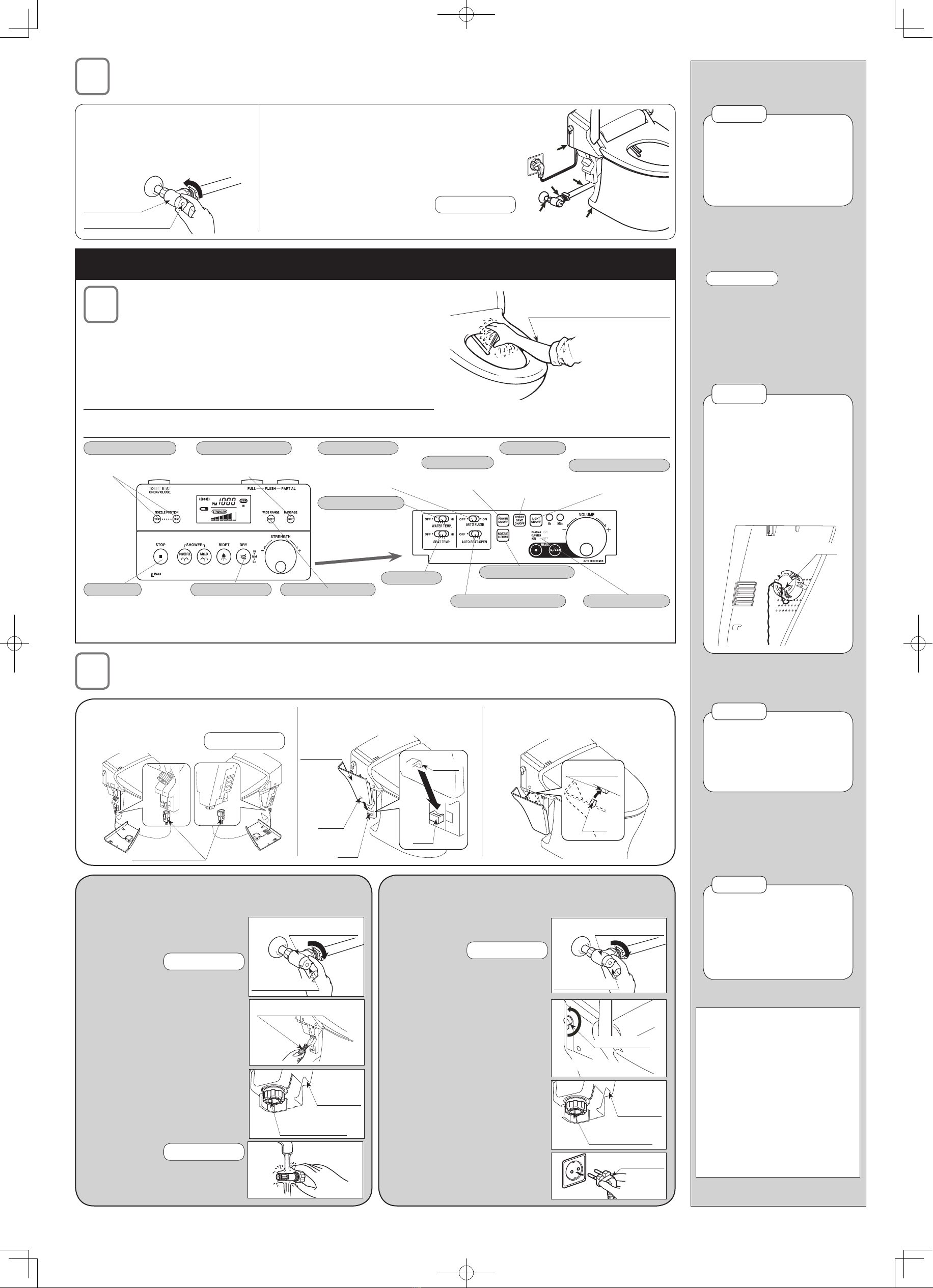
If the water ow is blocked, clean the
strainer.
(1) Cut off the ow of water by turning
the water shut-off valve's Open/Close
handle to the off position.
See NOTE 26.
(2) Press the ush switch on the remote
controller.
(3) Remove the decorator panel on the
left side of the shower toilet. Place a
washbasin or the like under the toilet
bowl strainer and remove the strainer.
(4) Remove the decorative panel on the
right side of the shower toilet. Place a
washbasin or the like under the shower
toilet strainer and remove the strainer.
(5) Clean the strainers.
(6) Install the strainers in their original
positions.
See NOTE 27.
(7) Open the water shut-off valve.
*If the water ow is poor after the strainers
are clean, check the supply water pressure.
Toilet Strainer
止水栓開.eps
Water Shutoff Valve
Open/Close Handle
Close
Bottom Right
Side of the
Body
Shower Toilet
Strainer
Drain out the water if a freeze is expected between the trial
operation is completed and handing the product to the customer.
(1) Close the water shutoff valve's
Open/Close handle.
See NOTE 26.
(2) Turn the ush lever toward the
front.
(3) Remove the decorative panel
on the left side of the shower
toilet, and open the toilet strainer
to drain the water out of the
water shutoff valve.
(4) Remove the decorative panel
on the right side of the shower
toilet. Place a washbasin or
the like under the shower toilet
strainer and remove the strainer
to drain water out of the shower
toilet.
(5) Reinstall the strainers, making
sure they are tightened securely.
(6) Remove the power plug from
the receptacle.
Power Plug
About 180°
Flush Lever
止水栓開.eps
Water Shutoff Valve
Open/Close Handle
Close
Bottom Right
Side of the
Body
Shower Toilet
Strainer
(1) Connect the side panel's speaker
connectors with the body so that their clip
comes to the outside.
See NOTE 25.
(3) Fit the clip on the top of the side panel
onto the clip holder on the body.
2) Fit the pawl on the bottom of the
side panel into the slot on the body.
化粧板外す2.eps
Side Panel
Slot
Slot
Pawl
Pawl
スピーカコネクタ.eps
Connector clip
化粧板外す1.eps
Clip Holder
Clip
Trial Operation (Follow the procedure below after installation work is completed.)
Check the shower and bidet spray.
2. Perform the same check with the bidet spray function.
1. Check the shower washing operation.
(1) With your forearm resting on the toilet seat, press the POWERFUL shower button.
The shower automatically stops in two minutes after the switch is turned on.
(2) When the nozzle extends, cover the tip of the nozzle with your hand to catch the
spray when the shower begins spraying.
(3) Press the STOP button to stop the shower spray.
*Since there is an occupied seat sensor, the
product’s shower, bidet and deodorizing functions
will not operate if you don't touch the seat.
Roll up your sleeve and
bring your bare arm in direct
contact with the toilet seat.
*Deodorizing starts outomatically when touching the toilet seat.
Moves the nozzle forward or
backward, washing a wider range.
WIDE RANGE
Open the lid.
Stops the posterior washing, bidet
washing and drying operations.
STOP
Adjusts the nozzle
position.
NOZZLE POSITION
Used to dry the parts that
became wet during washing.
DRY
Repeats washing strength
weak-strong cycle.
MASSAGE
Flushes the toilet
automatically when you
rise from the toilet seat.
AUTO FLUSH
Detects the user's presence in
the room and automatically opens
and closes the toilet seat lid.
AUTO SEAT OPEN
Turns the product’s
power on/off.
POWER ON/OFF
Saves power
by lowering
the toilet seat
temperature.
POWER SAVE
Lights up the oor and the
inside of the toilet bowl.
LIGHT (Dim Light)
Adjusts the
heated toilet seat
temperature.
SEAT TEMP.
Adjusts the temperature
of the shower and bidet
water.
WATER TEMP.
Emits ions that refresh
the air and make the
room comfortable.
Comfort Ions
Used to clean the nozzle.
NOZZLE CLEANING
Water leakage check
1. Turn the Open/Close handle of the water
shutoff valve to the fully open position and
turn on the ow of water to the product.
2. Check to make sure there is no water leakage.
(1) Operate the remote control unit, ushing the toilet
several times.
(2) Check each of the connections for water leakage.
At the same time, check if there is anything
abnormal about the operation of the ush lever, etc.
See NOTE 24.
3. Check the toilet's ushing action.
止水栓開.eps
Open/Close Handle
Water
Shutoff Valve
Open
Repeat the test to check on
water leakage from the water
supply and drain connections
several times. Water leakage
cannot be checked without
repeated water ow.
NOTE 24
Reference 3
The deodorizing cartridge has
already been installed in the
toilet.
●
Do not remove the strainer
with the water shutoff valve
opened.
Doing so may cause water
leakage from the strainer.
*
NOTE 26
When installing the strainers,
tighten them completely so
there is no gap.
If they are not tightened fully,
water could leak from the
strainers.
*
NOTE 27
When running the wire for
the speaker, be sure to t it
in the clip on the speaker as
shown in the gure below.
When installing the decorative
panel, there is danger of
the wire getting caught or
protruding outside the surface.
*
NOTE 25
スピーカ.eps
Clip
Check Sheet
Check for water leakage.
Water shutoff valve
Water supply hose connections
Bottom surface of toilet
Check remote control operation.
Is the water shutoff valve
completely opened?
Check
boxes
□
□
□
□
□
This manual suits for next models
1
Table of contents
Other Inax Plumbing Product manuals


Popular Plumbing Product manuals by other brands

Symmons
Symmons Duro 362SH Operation & maintenance manual

Grohe
Grohe EUROSTYLE 23 577 installation instructions

Lakes Bathrooms
Lakes Bathrooms Coastline Series Installation & maintenance instructions

Brizo
Brizo Rook T60861-GL installation instructions

SFA
SFA SANICOMPACT Star Eco installation instructions

Grohe
Grohe 29 025 manual


