InCoax In:xtnd User manual

Copyright © 2019 InCoax Networks AB. All rights reserved.
Confidential nder NDA.
User Manual
In:xtnd™ | Control | MA2.5 | 4

Copyright © 2018 InCoax Networks AB. All rights reserved.
Confidential nder NDA
Document History
Date Rev Originator Description
2018-12-03 V1.4
Johan Bodin
Thomas Svensson
Jesper Cederholm
Initial version converted from former system.
2019-02-18 V1.4_b3 Thomas Svensson Inx:tnd system release Version 1.0NC
2019-03-18 V1.4.2 Carl Elofsson Inx:tnd system release Version 1.0NC Approval
2019-06-0 V1.5 Jesper Cederholm Inx:tnd system release Version 1.1
2019-06-18 V1.4_b16 Johan Sandström Additions and corrections
2019-06-25 V1.4_b17 Claes Levinsson Additions and corrections
2019-06-26 V1.4_b18 Mikael Ovesson Additions and corrections
2019-06-2 V1.4_b19 Claes Levinsson Additions and corrections
2019-06-2 Rev. A Claes Levinsson First revision
2019-10-01 Rev. B Claes Levinsson Second revision
2019-10-09 Rev. C Claes Levinsson Third revision

Copyright © 2018 InCoax Networks AB. All rights reserved.
Confidential nder NDA
Contents
Read This First ............................................................................................................................... 1
When Using the Controller ...................................................................................................................... 1
Network Req irements ........................................................................................................................... 1
Installation Environment ......................................................................................................................... 2
Storage Environment ............................................................................................................................... 2
Definitions and Abbreviations ....................................................................................................... 3
Package Content ............................................................................................................................ 5
1 Introd ction .......................................................................................................................... 6
1.1
The In:xtnd™ System .................................................................................................................. 6
1.2
The In:xtnd™ | Manage | MA2.5 ............................................................................................... 6
1.3
The In:xtnd™ | Control | MA2.5 | 4 ........................................................................................... 6
1.4
The In:xtnd™ | Access | MA2.5 | 2 ............................................................................................ 6
1.5
The In:xtnd™ Q ality of Service ................................................................................................. 7
1.6
The In:xtnd™ | Basic Prod ct Connection .................................................................................. 7
2 Getting Started – Controller Web Interface .......................................................................... 8
2.1
Accessing the Controller Web Interface .................................................................................... 8
2.2
User Levels and Permissions ...................................................................................................... 8
3 Web Interface ..................................................................................................................... 10
3.1
Overview .................................................................................................................................. 10
3.2
Home ........................................................................................................................................ 10
3.3
Modems ................................................................................................................................... 11
3.3.1
Overview ......................................................................................................................... 11
3.3.2
General Data Protection Reg lation ............................................................................... 11
3.3.3
Adding and Config ring Modems ................................................................................... 11
3.3.3.1
Adding Modems Man ally ....................................................................................... 12
3.3.3.2
Adding Modems A tomatically ................................................................................ 14
3.3.3.3
Service 14
3.3.3.3.1
Adding a New Service to a Modem ................................................................... 14
3.3.3.4
Modem Details ......................................................................................................... 15
3.3.3.5
Firmware .................................................................................................................. 17
3.3.3.6
Modem Statistics ...................................................................................................... 17
3.3.4
Edit the Config ration of a Modem ................................................................................ 17
3.4
Management ............................................................................................................................ 18
3.4.1
Overview ......................................................................................................................... 18
3.4.2
M lticast ......................................................................................................................... 18
3.4.2.1
Add M lticast ........................................................................................................... 19
3.4.2.2
Edit a M lticast Gro p.............................................................................................. 19
3.4.3
Port Settings .................................................................................................................... 19
3.4.4
Service VLAN ................................................................................................................... 21
3.4.4.1
Adding VLAN ............................................................................................................. 21
3.4.4.2
Config re M lticast Gro ps for VLAN ...................................................................... 21
3.4.5
Service & QoS .................................................................................................................. 23
3.4.6
Priority Settings ............................................................................................................... 25
3.4.7
Advanced Settings ........................................................................................................... 26
3.4.8
Reboot (Controller) ......................................................................................................... 27
3.5
S pport .................................................................................................................................... 27

Copyright © 2018 InCoax Networks AB. All rights reserved.
Confidential nder NDA
3.5.1
S pport - Ping .................................................................................................................. 27
3.5.2
S pport - Hardware ......................................................................................................... 28
3.6
Statistics ................................................................................................................................... 28
3.7
Settings..................................................................................................................................... 30
3.7.1
My Acco nt ..................................................................................................................... 30
3.7.2
Users ............................................................................................................................... 30
3.7.2.1
Creating New Users .................................................................................................. 30
3.7.3
Network .......................................................................................................................... 31
3.7.4
Time Settings ................................................................................................................... 31
3.7.5
DNS Settings .................................................................................................................... 32
3.7.6
Management System Settings ........................................................................................ 32
3.7.7
Basic ................................................................................................................................ 33
3.7.8
SSL ................................................................................................................................... 34
3.7.9
Import/Export ................................................................................................................. 35
3.7.10
Firmware ......................................................................................................................... 35
4 Specifications ...................................................................................................................... 36
5 Legal Information ................................................................................................................ 38
5.1
Reg latory Notice and Statement (Class A) ............................................................................. 38
5.1.1
United States of America ................................................................................................ 38
5.1.2
Canada ............................................................................................................................ 38
5.1.3
E ropean Union .............................................................................................................. 38
6 Disposal of Eq ipment ........................................................................................................ 39
6.1
For B siness Users in the E ropean Union .............................................................................. 39
6.2
Disposal in Co ntries O tside the E ropean Union ................................................................. 39
6.3
Battery Symbol ......................................................................................................................... 39

Copyright © 2018 InCoax Networks AB. All rights reserved. 1
Confidential nder NDA
Read This First
Always make s re to connect all coaxial cables and network cables before connecting the power cable. This
m st be done to avoid electrical shock and to avoid damage to the nit. Gro nd loops might b ild p eno gh
electrical charge to give an electrical shock if not properly connected before connecting the power cord. Make
s re to connect the Cable TV (CATV) amplifier’s gro nd connection to the
Controller
nit if both the CATV
amplifier and
Controller
are installed in the same physical location. If the CATV-amplifier is located far away on
the coaxial network, the
Controller
nit m st not be gro nded beca se this will create a gro nd loop.
When Using the Controller
The
Controller
is designed to operate on 48 VDC. If the nit is
not
powered sing the power s pply delivered
with the
Controller
, b t in any other way directly or indirectly with 48 VDC, a 3 A f se
must be
fitted to the
power cable.
Please observe the following:
•
Do not stick any foreign objects, like metal or flammable objects into the
Controller
or its ventilation holes,
as this can ca se fire or electric shock.
•
Do not remove the cover or modify it in any way.
-
High voltages which can ca se severe electric shocks are present inside the
Controller
. For any
inspection, adj stment, and repair work please contact yo r local InCoax dealer. The warranty is void if
the cover is opened.
-
Never attempt to repair this prod ct yo rself. Improper repair work can be dangero s. Never
disassemble or modify this prod ct. Tampering with this prod ct may res lt in inj ry or fire.
•
Do not handle the power s pply pl g with wet hands as this may ca se electric shocks.
•
Do not se in locations s bject to high h midity or d st levels, as this may ca se damage to the eq ipment
or start a fire.
•
Do not do anything that may damage the power cable. When disconnecting the power cable, p ll on the
pl g body, not the cable.
•
Do not damage a power cable, make any modifications to it, place heavy objects on top of it, heat it, place
it near any hot objects, twist it, bend it excessively or p ll it. To do so may ca se fire and electric shock. Yo
sho ld discard the power cable if it is damaged in any way.
•
The power cable shall also be discarded if the pl g is damaged.
•
Do not place heavy objects on top of the
Controller
.
•
Sec rely insert the power s pply pl g as far as it will go.
•
Before moving the
Controller
npl g all cables connected to it.
It is recommended to npl g the power s pply from the wall o tlet or the nit if the
Controller
is not going to
be sed for any prolonged length of time.
Network Requirements
Please consider the following d ring the installation of the
Controller
.
The risk of potential differences and the spread of voltage from fa lty eq ipment are largely linked to the
design of the power installation in the b ilding. If the coax connections are not galvanically separated according
to the standard EN60728 then a galvanic separator, e.g. Soontai Isolator IS9 SG, shall be sed between the coax
connection and the
Controller
.
In terms of potential eq alization, the EN 50083-1 and EN60728 shall be followed. Cable distrib tion systems
shall be designed and constr cted so that no dangero s voltages can occ r in the external cond ctors of any
cables or in metal cases on passive parts.
Warning
If the
Controller
is installed in an environment where the s rro nding temperat re is at least 50
o
C (degrees
Celsi s), the coax connectors can reach a temperat re of at least 85
o
C. In this case the coax connectors m st
not be covered with or in contact with comb stible materials d e to the risk of fire.

2 Copyright © 2018 InCoax Networks AB. All rights reserved.
Confidential nder NDA
Installation Environment
Install the Controller in a site free from strong electromagnetic field generators (s ch as motors), vibration,
d st, and direct expos re to s nlight.
Install the Controller in a fairly cool and dry place for the acceptable temperat re and h midity operating
ranges. See section 4 for the act al temperat re ranges.
Install the Controller on a st rdy, level s rface that can s pport at least 5 kg (11 lbs) of weight. Leave at least
10 cm (4 inches) of space at the front for the coax cables.
Connect a 75-ohm terminator (F-connector) in all coax ports that are not sed on the Controller.
Storage Environment
The ideal storage location is a dry and well ventilated location, e.g. in a space with climate-control. Please refer
to section 4 on page 36 for more details abo t the specified environmental conditions.

Copyright © 2018 InCoax Networks AB. All rights reserved. 3
Confidential nder NDA
Definitions and Abbreviations
The following definitions are sed in this doc ment:
Definition Description
Access Modem
In:xtnd™ | Access | MA2.5 | 2Eth – is a coax to Ethernet network terminal providing 2×1 Gbps
Ethernet interfaces. In:xtnd Access 2 Ethernet comm nicates with the In:xtnd
Controller
4-port
and is based on the MoCA Access™ 2.5 standard. The In:xtnd
Access
Modem
is installed in the
s bscribers’ premises. This device will be referred to as the
Access
Modem
or j st the
Modem
in
the doc ment.
Controller
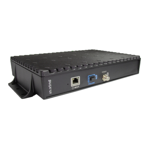
In:xtnd™ | Control | MA2.5 | 4 – is a 4-channel broadband over coax access node, capable of
2.5 Gbps per RF-port, or a total of 10 Gbps, s pporting p to 124 In:xtnd
Access
Modems
. It
comm nicates with In:xtnd Access sing the MoCA Access 2.5 standard.
Customer
End ser.
Diplexer
In:xtnd™ | Combine I MA 2.5 is a high-performance freq ency combiner. The combiner is
designed to be sed for connecting one or two MoCA Access Channels for an In:xtnd
Controller
and FM/VHF into a single coaxial cable combining FM/VHF and broadband access in a single
coax cable.
Management
System
In:xtnd™ | Manage | MA 2.5 – is a, clo d-based, advanced element manager with feat res for
In:xtnd
Controller
deployment, control, and s pervision of the coax link conditions. It incl des
essential f nctions for service provisioning and network management.
MoCA Access
In:xtnd MoCA Access is point-to-m ltipoint access network sol tion serving p to 31
Modems
(clients) per coax cable loop. It is designed to coexist with legacy services s ch as TV, DOCSIS,
and cell lar (4G/5G) technologies. The operating freq ency range is 400 MHz – 1675 MHz.
The following abbreviations are sed in this doc ment:
Abbreviation Description
CAM Coax Access Modem -
This device will be referred to as the
Access
Modem
or j st the
Modem
in
this doc ment.
CATV
Cable TV.
CLC
Coax Link
Controller
. It will be referred to as the
Controller
in this doc ment.
C-VLAN
C stomer VLAN - is the VLAN that the c stomer ses, or sees (the inner tag). CVLAN is the VLAN
tag the c stomer is sing on their own devices. (See QinQ.)
DHCP
Dynamic Host Config ration Protocol – an a tomatic config ration protocol sed to
a tomatically assign IP addresses to devices on a TCP/IP network.
IaaS
Infrastr ct re as a Service – a form of clo d comp ting that provides virt alized comp ting
reso rces over the internet.
IGMP
Internet Gro p Management Protocol – a protocol sed to establish m lticast gro p
membership.
IPTV
Internet Protocol TeleVision – the delivery of television content over Internet Protocol (IP)
networks. IPTV is a technology for watching television sing Internet Protocol over LAN or the
Internet, instead of watching TV over cable or satellite.
MAC Address
Media Access Control address – a niq e identifier assigned to a Network Interface Controller
(NIC) for comm nications at the data link layer of a network segment. MAC addresses are sed
as a network address for most IEEE 802 network technologies, incl ding Ethernet, WiFi, and
Bl etooth.
MGT
Denotes the Management port on the
Controller
.
MVR
M lticast VLAN Registration
Nmap
Network Mapper – a free and open-so rce network scanner. Nmap is sed to discover hosts and
services on a comp ter network by sending packets and analyzing the responses.
PPPoE
Point-to-Point Protocol over Ethernet is a network protocol for encaps lating PPP frames inside
Ethernet frames.
QinQ
The 802.1Q-in-802.1Q (QinQ) technology improves the tilization of VLANs by adding another
802.1Q tag to tagged packets. (See C-VLAN and S-VLAN.)
QoS
Q ality of Service - is the ability to provide different priority to different applications, sers, or
data flows, or to g arantee a certain level of performance to a data flow.

4 Copyright © 2018 InCoax Networks AB. All rights reserved.
Confidential nder NDA
Abbreviation Description
RX
Receive signal.
SaaS
Software as a Service – a software licensing and delivery model in which software is licensed on
a s bscription basis and is centrally hosted.
SFP/SFP+
Small Form factor Pl ggable transceiver. SFP ≤ 1 Gbps and SFP+/Enhanced ≤ 10 Gbps.
SOAP
Simple Object Access Protocol – protocol for exchanging str ct red information.
SSL
Sec re Sockets Layer is a standard technology for keeping an internet connection sec re and
safeg arding any sensitive data that is being sent between two systems, incl ding potential
personal details.
S-VLAN
Service VLAN - is the VLAN that the service provider network sees (the o ter Q-tag). SVLAN is the
VLAN the service provider p ts all the c stomer traffic in. (See QinQ.)
TCP/IP
Transmission Control Protocol/Internet Protocol – architect re for data comm nication over
networks.
ToS
Type of Service.
Trunk
The Tr nk is the plink port from the
Controller
. It ses SFP mod les.
TX
Transmit signal.
URL
Uniform Reso rce Locator - the address of a reso rce on the Internet.
UTP
Unshielded Twisted Pair.
Web GUI
Web Graphical User Interface – a ser interface that allows sers to interact with In:xtnd
electronic devices thro gh a web page.
XML
eXtensible Mark p Lang age – lang ages which describes the information.

Copyright © 2018 InCoax Networks AB. All rights reserved. 5
Confidential nder NDA
Package Content
Check that yo have the accessories and items as shown in Table 1.
(The images are ill strations and may differ from the real items.)
Table 1 - Contents of the package.
Product Item Description Item picture
Controller
Broadband over coax access node, capable of
2.5 Gbps per RF-port, a total of 10 Gbps.
Mounting
handles
Mo nting handles for wall mo nt (4 pcs).
Quick Guide
Q ick G ide

6 Copyright © 2018 InCoax Networks AB. All rights reserved.
Confidential nder NDA
1Introduction
1.1 The In:xtnd™ System
InCoax™ is a provider of broadband access sol tions leveraging existing in-b ilding coaxial cable networks. The
In:xtnd System consists of a Management System (In:xtnd™ | Manage) which manages Controllers (In:xtnd™ |
Control) installed in, or near, b ildings and Modems (In:xtnd™ | Access ) installed in c stomers’ homes. An
ill stration of the management system can be seen in Figure 1. The Modem is easily installed by the c stomers
witho t any req irements for config ration. This architect re makes the system very flexible. Once the
Controller has been installed in, or near, the b ilding the only req ired operation to connect new c stomers is
to provide them with a Modem. As soon as the Modem has been connected to the coax network, it will
a tomatically be detected and properly config red by the Controller thro gh the Management System.
The typical In:xtnd System consists of one Management System which handles h ndreds of Controllers and
tho sands of Modems. If there is a legacy cable-TV service in the b ilding the TV signal can be m ltiplexed with
the broadband signal sing the Diplexer (In:xtnd™ | Combine). The Management System is sed as a c stomer
config ration, monitoring, and provisioning tool thro gh a web interface. In larger networks the Controller
f nctions sed by the Management System can be accessed by any other provisioning system or Operating
S pport System thro gh a SOAP/XML interface.
Figure 1 — Overview of the Management System.
1.2 The In:xtnd™ | Manage | MA2.5
The Management System is a software package installed in a Lin x environment. It manages the Controllers
and Modems. The Management System a tomatically detects new Modems and manages the mapping of
s bscriber data. It also collects and presents comm nication statistics parameters and priorities. F rthermore,
it meas res and presents the RF link q ality in real time and handles vario s alarms to the operator.
1.3 The In:xtnd™ | Control | MA2.5 | 4
The Controller acts as a bridge between the Ethernet access network and c stomers’ local area Ethernet, sing
the in-b ilding coaxial network as transport for data traffic to the Modems. The Controller comm nicates with
all Modems, over dedicated RF channels, in the coaxial network to manage their individ al config ration,
enforces traffic, and sec rity policies. It also collects and stores traffic statistics data from the network.
1.4 The In:xtnd™ | Access | MA2.5 | 2
The Access Modem is an Ethernet network terminal. It connects to any antenna o tlet in the s bscribers’
homes for easy self-installation. It comm nicates with the Controller to get config ration parameters and
connects to the s bscribers’ local area Ethernet (e.g. s ally a residential gateway) sing Ethernet CAT cables
with RJ45 pl g. (InCoax recommends sing CAT5e cable type as a minim m for best performance.) The
firmware of the Modem can be pgraded from the Controller.

Copyright © 2018 InCoax Networks AB. All rights reserved. 7
Confidential nder NDA
1.5
The In:xtnd™ Quality of Service
The In:xtnd Controller s pport p to fo r q e es, broadcast, and m lticast Q ality of Service (QoS),
prioritization between nicast and broadcast/m lticast and classification. Unicast QoS can be set individ ally
for each Modem.
1.6
The In:xtnd™ | Basic Product Connection
Figure 2
shows an example of the in-b ilding connections for the basic prod cts.
Figure 2 — Overview of the in-b ilding connections.

8 Copyright © 2018 InCoax Networks AB. All rights reserved.
Confidential nder NDA
2Getting Started – Controller Web Interface
The Controller can be managed via the management port
MGT
. Please refer to
Figure 3
where the front of
the Controller can be seen.
2.1
Accessing the Controller Web Interface
1.
Connect a comp ter with an Ethernet cable to the Management port on the Controller,
marked
MGT
. (InCoax recommends sing the cable type CAT5e as a minim m for best
performance.)
2.
Set a static IP for yo r comp ter connection, for example 192.168.144.100 (or any IP
between 192.168.144.1 and 192.168.144.254 b t not the same as the defa lt IP address)
and S bnet Mask 255.255.255.0.
3.
Open yo r web browser and go to the URL https://192.168.144.20. The web page in
Figure 4
will be displayed. Inp t the following to log in:
a.
Defa lt Username:
incoax
b.
Defa lt Password:
incoax
Figure 3 — The front of the Controller.
Figure 4 — The login page.
2.2
User Levels and Permissions
There are two different ser levels with different p rposes and permissions:
View Only
: Demonstration and s pervision. The View Only sers can view some managed objects and
settings, b t cannot add or change anything.
Admin
: Controller and Modem management. The Admin sers can add and change managed objects and
settings. This is the standard ser level.
Table 2
gives a detailed view of what the two ser levels are allowed to do.

Copyright © 2018 InCoax Networks AB. All rights reserved. 9
Confidential nder NDA
Table 2 — User level permissions.
Operation View Only Admin
View Controller
View Modem
View Service
View Controller Statistics
Use port Spectr m
View Modem Statistics
View Alarms
View Modem Defa lt Config rations
View Users
View SOAP Config rations
Add/edit/delete Modem
Add/edit/delete Service
Upgrade Modem Firmware
Add/edit/delete M lticast Gro ps
Edit Coax Ports
Add/edit/delete Service VLAN
Edit Service and QoS
Edit Priorities
Edit Advance Settings
Use Ping and Tracero te Tools
View Hardware
Download Logs
View Settings
Add/edit/delete Settings
Add/edit/delete Network Settings
Modify Users
Modify Own Acco nt Settings
Modify SOAP Config ration
Manage Controller Firmware
Reboot Controller

10 Copyright © 2018 InCoax Networks AB. All rights reserved.
Confidential nder NDA
3Web Interface
This section gives a detailed description on how to se the Controller Web Interface.
3.1
Overview
The web interface provides the possibility to config re and manage settings, and inspect performance and
statistics. Each of the tabs
HOME
,
MODEMS
,
MANAGEMENT
,
SUPPORT
,
STATISTICS
,
SETTINGS
, and
LOGOUT
are described below in the following sections. All web pages have their name displayed j st below the men
bar. This is to make it easier to locate where yo are in the web interface.
3.2
Home
The
HOME
tab in
Figure 5
is shown after the login is completed. It displays the basic config ration parameters
(
LAN Settings
and
Management VLAN Settings
), some stat s information, and some statistics.
Figure 5 — Web page Home for the Controller.
The settings can only be edited by a ser with Admin permissions, as was stated in
section 2.2
.
1.
Click on
HOME
to see the Home tab.
2.
To edit the
Basic Settings,
click on the symbol in the same box.
3.
To edit the
LAN Settings
, click on the symbol in the same box.
4.
To edit the
Management VLAN Settings
, click on the symbol in the same box.
The following information can be fo nd on the
HOME
tab:
•
The box
In oax L
contains information abo t the hardware type, software version, and MAC address that
are valid for the specific Controller. (Please note that CLC stands for Coax Link Controller, i.e. the Controller.)
•
The box
Basic Settings
contains information abo t the hardware version and its location.
•
The box
LAN Settings
contains information of which IP address that is sed to manage the Controller and the
S bnet for the network.
•
The box
Management VLAN Settings
contains information abo t the VLAN ID that is sed for management,
IP address for the management VLAN, S bnet for the network, and Defa lt Gateway.
•
The box
Hardware status
contains information abo t the hardware; Chassis temperat res, BIOS version,
n mber of Software reboots, and Power cycle reboots.
•
The table in the lower part of
Figure 5
provides a q ick performance overview of the Controller.

Copyright © 2018 InCoax Networks AB. All rights reserved. 11
Confidential nder NDA
Chassis
: This gives an indication of the temperat re inside the chassis. There are fo r possible colors:
Good (green) - Stat s OK.
Warning (yellow) - Stat s warning. Small margin to Critical stat s.
Critical (orange) - Maintenance might be req ired. Contact yo r local sales representative.
Fail re (red) - Maintenance or replacement might be req ired. Contact yo r local sales representative.
3.3
Modems
3.3.1
Overview
The
MODEMS
tab displays all Access Modems that have been added to the specific Controller nit. All of these
Modems can be managed from this tab.
Hover over
MODEMS
in and click on
OVERVIEW.
This displays a table with information, as shown in
Figure 6
,
abo t
MA
,
OAX
,
STAT
,
LO ATION
,
VLAN
,
STATUS
,
MHz
,
SET
, and
SERVI E
for every Modem that is
connected with the Controller.
Table 3
has more information abo t some of the different parameters.
•MA
- displays the Modem MAC address. By clicking once on the header
MA
the Modems will be sorted
alphan merically in accordance with their MAC addresses. If yo click once more the sorting will be
reversed.
•OAX
- displays which coax port on the Controller a Modem is connected to.
•STAT
- press the symbol to be directed to the specific Modem’s statistics.
(See
section
3.6
for more information.)
•LO ATION
- displays the location set in the Modem.
•VLAN
- display Service VLAN setting.
•STATUS
- green or red means link or no link, respectively, between the Controller and the Modem. By
clicking once on the header STATUS the Modems will be sorted according to their stat s green/red. If yo
click once more the sorting will be reversed. If the stat s is green yo can click on the stat s indicator and
some sef l information will be displayed (e.g. config ration parameters and ptime).
•MHz
- displays the freq ency set d ring the config ration of the Modem. (See
Figure 8
and
Table 3
for more
information.)
•SET
- please note that clicking on the will set the Active Service to Defa lt for the specific Modem. See
section 3.3.3.2
and
Table 4
for more information.
•SERVI E
- displays the name for the Service that is set.
•DELETE
- click on the
symbol and the specific Modem will be deleted.
3.3.2
General Data Protection Regulation
In the field Location yo can enter the real location of the Modem in the b ilding. (See
Figure 7
and
Table 3
.)
Please note that this can be in conflict with General Data Protection Reg lation (GDPR). Before yo enter any
information abo t the location make s re that it is in agreement with GDPR and/or any local legal aspects. Also
note that there may be sec rity aspects that can affect what kind of information co ld be in the database.
3.3.3
Adding and Configuring Modems
At the far right in
Figure 6
there is an
Options
men . Here it is possible to add a new Modem or to send a new
config ration to pdate the Modems. When a Modem is added man ally to the Controller it will get all
config ration parameters from the “defa lt” service. All parameters can man ally be reconfig red, or a new
service can be assigned to each Modem. The parameters are described in
Table 3
.
Please note that yo
must first
add a Service VLAN as described in
section 3.4.4.1
on page 21.
Figure 6 – Overview of the connected Modems.

12 Copyright © 2018 InCoax Networks AB. All rights reserved.
Confidential nder NDA
3.3.3.1
Adding Modems Manually
1. Make s re that the Modem is
switched off
.
2. In the main men , hover over
MODEMS
and click on
OVERVIEW.
3. Click on
ADD MODEM
in the
Options
men to the right. (See
Figure 7
.)
4. Enter the MAC address of the Modem in the field
MAC
. The MAC address can be fo nd on the prod ct label
placed on the Modem.
5. In the
Service & QoS
, as seen in
Figure 8
, set the MoCA band and freq ency to the same val es as the coax
port. This is to ens re that the Modem can establish a link to the intended coax port.
6. Config re other relevant parameters like VLAN, priorities, etc.
7. Click on the b tton
Add modem
to add this Modem.
8. Connect the Modem to the coaxial network and connect the power adapter.
Figure 7 — Add Modem - Basic Settings.
Figure 8 — Add Modem - Service and QoS; Switch Config ration

Copyright © 2018 InCoax Networks AB. All rights reserved. 13
Confidential nder NDA
Table 3 — Description of the Add Modem parameters.
Term Value
[Default Setting] Definition
Basic Settings
MAC
MAC MAC address for the Modem.
Location
User defined
location
Text string describing the location of the Modem. Set to A to discover
when the Modem has been a tomatically detected and added by the
Controller. This can be changed when the Modem has been added.
Service VLAN n id
n = 1 - 4
User added VLAN
Defines which of the VLAN’s available on the Controller that co ld be
available in the Modem. If there is a Service Defa lt VLAN it will show p
as a s ggestion.
DHCP Option 82
User defined DHCP Relay Agent Information Option parameters
DHCP Max Clients
User defined Defines max. conc rrent clients that are allowed to connect to this
Modem. 0 (zero) means nlimited.
Admission Allowed
On/Off [On] Defines whether the Modem is allowed to be associated with the
Controller or not. Check the checkbox to allow admission.
Automatic Power
Control
On/Off [On]
Enable or disable a tomatic power control. The benefit with a tomatic
power control is that the risk of interfering with other analog e devices
is red ced d e to overall lower transmit power levels. External
interference problems can be red ced / avoided by disabling the power
control mechanism. Power control is enabled when the checkbox is
checked.
Power
0 - 10 [10]
This parameter sets the transmit power level when a tomatic power
control is disabled and sets the max. power level when a tomatic power
control is enabled. Each red ction in the index is a 3dB red ction in the
transmit power level.
When sing the Power Amplifier (PA, "PA On") in the Controller, the
MoCA chip needs to back off to avoid sat ration of the PA, so the max.
TX Power sho ld be set to 8 or less to avoid sat ration of the PA.
When NOT sing the Power Amplifier (PA, "PA Off") in the Controller,
max. TX Power sho ld be set to 10.
Power Control Rate
0 - 680 Mbps
[680]
This parameter is the req ired physical bit rate that will be targeted in
the a tomatic power control mode and is the speed per 100 MHz
channel. If the target MAC rate is 2500 Mbps MAC rate, the Power
Control Rate sho ld be set to 680 Mbps (5 × 680 Mbps = 3400 Mbps PHY
rate), as a lot of the PHY rate capacity will be sed for the MoCA Access
2.5 based MAC.
PA/Attenuation
[Off/Off]
Amplified o tp t and/or atten ated inp t. (Defa lt Off/Off). Observe
that “PA On” req ires the ser to modify the Power parameter
described above.
US Speed limit
[0]
Max. pstream traffic from the Modem. The defa lt val e of zero, 0,
means that no pstream limit is applied in the Modem and all policing is
done in the Controller.
MoCA Band
[A-D] Choose freq ency range. Options A-A/A-B/A-C/A-D or
A-E.
Frequency (1 of)
450 - 1625 MHz
[1150] The centre freq ency the Modem is to operate on.
QoS (Q0 - Q3)
Upstream peak
0 - 2000 Mbps
[2000] Max. nicast pstream traffic per q e e.
Upstream
guaranteed
0 - 2000 Mbps
[100] G aranteed nicast pstream traffic per q e e.
Downstream peak
0 - 2000 Mbps
[2000] Max. nicast downstream traffic per q e e.
Downstream
guaranteed
0 - 2000 Mbps
[100] G aranteed nicast downstream traffic per q e e.
Burst peak
0 - 131071 bytes
[80000] B rst traffic peak val e, also called peak b rst size – PBS.

14 Copyright © 2018 InCoax Networks AB. All rights reserved.
Confidential nder NDA
Term Value
[Default Setting] Definition
Burst guaranteed 0 - 131071 bytes
[4096] B rst traffic g aranteed val e, also called committed b rst size, CBS.
Switch Config ration
VLAN passthrough [On]
If it is marked it means that each port allows packets with tagged VLAN
(defined in each Modem) to pass thro gh the Modem switch. If it is not
marked, then packets with VLAN tag (other than defined in native) are
dropped.
Enable port On/Off [On] Activate/disable switchport.
Native VLAN (U) Service VLAN 1 - 4
id
Packets belonging to the VLAN specified here will leave the switch port
ntagged and packets received on this port will leave the switch tagged
with this VLAN.
Tagged VLAN Service VLAN 1 - 4
id
A max. of 3 Tagged VLANs can be s pported, packets belonging to the
VLAN specified here will leave the switch port tagged and tagged packets
(with this VLAN) received on this port will leave the Controller tagged.
3.3.3.2
Adding Modems Automatically
Before starting to add Modems a tomatically, it is good to check how they are going to be
config red. Adding Modems a tomatically can save a lot of time, b t the opposite can also be
tr e if the defa lt settings for the Modems are wrong.
1. Set
Service default
in the Controller.
2. In the main men , hover over
MODEMS
and click on
SERVICES.
3. Click on the name
default
in the col mn
SERVI E
in the displayed table. (See
Figure 9.
)
4. Set the desired defa lt settings.
5. Connect the power to the Modem(s).
6. The Modem(s) will soon be fo nd by the Controller and will be correctly associated.
Figure 9 — Overview of the Modem Services.
3.3.3.3
Service
A service is a config ration template for Modems. A “defa lt service” always exists on a Controller. This service
can be edited b t it cannot be deleted. The service on the Controller sho ld not be sed if yo are sing the
InCoax Management System (Manage). Please see
section
3.7.6
on page 32 and the Manage User Man al for
more information.
3.3.3.3.1
Adding a New Service to a Modem
1. In main men , hover over
MODEMS
and click on
SERVICES.
2. Click on
ADD SERVICE
in the Options panel to the far right in
Figure 9
.
3. Config re the parameters and make s re the checkbox Service active is marked. See
Figure 10
,
Figure 11
,
and
Table 4
.
4. Click on the b tton
Add
at the bottom of the web page.
5. In the main men , hover over
MODEMS
and click on
OVERVIEW
. Yo will then come to the page seen in
Figure 6
.
6. Assign the new service to one of the Modems by clicking the symbol (
SET
) on the selected Modem.
7. Click on
SEND UPDATES
to save the changes.

Copyright © 2018 InCoax Networks AB. All rights reserved. 15
Confidential nder NDA
Figure 10 — Add Service - Basic Settings.
Figure 11 — Add Service - Service and QoS; Switch Config ration.
3.3.3.4
Modem Details
To get access to more details abo t the Modem go to the main men , hover over
MODEMS
and click on
DETAILS.
A web page as shown in
Figure 12
will be displayed. This contains some statistical data from the Modems. See
Table 5
for more details. Sorting of the listed Modems can be done for the headers MAC, COAX, LOCATION, S,
CAM UPTIME, and VERSION.
Figure 12 — Modem - Details.

16 Copyright © 2018 InCoax Networks AB. All rights reserved.
Confidential nder NDA
Table 4 — Description of the Add Service parameters.
Term Value
[Default Setting] Definition
Basic Settings
Name User defined Name
[Blank]
Text string describing the Service. This can be changed when the
Modem has been added.
Service active On/Off [Off] Defines which service that is active via SET f nction in the MODEM -
OVERVIEW tab. (See Figure 6.)
Service VLAN n id
n= 1 - 4 User added VLAN Defines which of the VLANs are available on the Controller that co ld
be available for the Modem.
DHCP Option 82 User defined DHCP Relay Agent Information Option parameters.
DHCP Max Clients User defined Defines max. conc rrent clients that are allowed to connect to this
Modem.
Admission Allowed On/Off [On] Defines whether the Modem is allowed to be associated with the
Controller or not. Check the checkbox to allow admission.
Automatic Power
Control On/Off [On]
Enable or disable a tomatic power control. The benefit with a tomatic
power control is that the risk of interfering with other analog e devices
is red ced d e to overall lower transmit power levels. External
interference problems can be red ced / avoided by disabling the
power control mechanism. Power control is enabled when the
checkbox is checked.
Power 0 - 10 [10]
This parameter sets the transmit power level when a tomatic power
control is disabled and sets the max. power level when a tomatic
power control is enabled. Each red ction in the index is a 3 dB
red ction in the transmit power level.
Power Control Rate 0 - 2048 Mbps [680] This parameter is the req ired physical bit rate that will be targeted in
the a tomatic power control mode.
PA/Attenuation [Off/Off] Amplified o tp t and/or atten ated inp t. (Defa lt Off/Off).
US Speed limit 0 Max. pstream traffic from Modem.
MoCA Band [A - D] Choose freq ency range. Options A - A/A - B/A - C/A - D or A - E.
Frequency (1 of] 450 - 1625 MHz
[1150] The centre freq ency the Modem is to operate on.
QoS (Q0 - Q3)
Upstream peak 0 - 2000 Mbps
[2000] Max. nicast pstream traffic per q e e.
Upstream guaranteed 0 - 2000 Mbps [100] G aranteed nicast pstream traffic per q e e.
Downstream peak 0 - 2000 Mbps
[2000] Max. nicast downstream traffic per q e e.
Downstream
guaranteed 0 - 2000 Mbps [100] G aranteed nicast downstream traffic per q e e.
Burst peak 0 - 131071 [80000] B rst traffic peak val e.
Burst guaranteed 0 - 131071 [4096] B rst traffic g aranteed val e.
Switch Config ration
VLAN passthrough [On]
If it is marked it means that each port allows packets with tagged VLAN
(defined in each Modem) to pass thro gh the Modem switch. If it is not
marked, then packets with VLAN tag (other than defined in native) are
dropped.
Enable port On/Off [On] Activate/disable switchport.
Native VLAN (U) Service VLAN 1 - 4 id
Packets belonging to the VLAN specified here will leave the switch port
ntagged and packets received on this port will leave the switch tagged
with this VLAN.
Tagged VLAN Service VLAN 1 - 4 id
Packets belonging to the VLAN specified here will leave the switch port
tagged and tagged packets (with this VLAN) received on this port will
leave the Controller tagged.
Table of contents
Other InCoax Controllers manuals
Popular Controllers manuals by other brands
Viconics
Viconics R850 Series manual

NEXCOBOT
NEXCOBOT RCB600 user manual

J&E Hall
J&E Hall Fridgewatch 2100 Installation, operating and maintenance manual
Orbit Merret
Orbit Merret OM 351 manual
National Instruments
National Instruments PXIe-8881 Getting started guide
Micronix
Micronix MMC-110 Series quick start guide

eMotionLighting
eMotionLighting EML1205 instruction manual

Gira
Gira 2100 Series manual

Honeywell
Honeywell HC900 Installation and user guide
Sentera Controls
Sentera Controls STR-1 Mounting and operating instructions
Samson
Samson TROVIS 6495-2 Mounting and operating instructions
Atlantic
Atlantic TWVSC product manual
