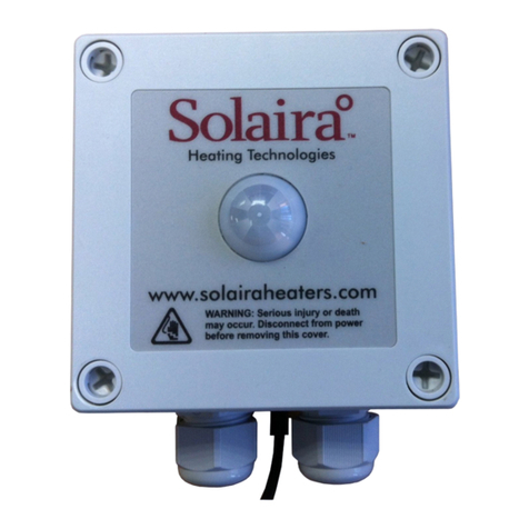
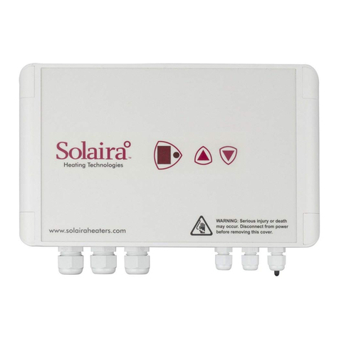
Solaira SMRTOCC60 Instruction Manual

Due to ongoing product improvements, specifications and dimensions are subject to change without notice and without incurring obligations.
IOM ▪SMRTOCC60/40 Rev 2. 11.19.22 1
Solaira SMaRT Occupancy On/Off Control
SMRTOCC60 and SMRTOCC40
Installation & User Manual
KEEP THESE INSTRUCTIONS FOR FUTURE REFERENCE
SAFETY WARNING
ALL INSTALLATIONS/SERVICE MUST ONLY BE
PERFORMED BY A LICENSED/CERTIFIED ELECTRICIAN
TO LOCAL AND NATIONAL ELECTRICAL CODE (NEC).
WARNING: SHOCK AND FIRE HAZARD:
•Serious injury or death could occur
•Disconnect ALL power sources before removing back panel. Power should only be re-connected after
electrical installations are complete and back cover replaced
•Be certain the power source conforms to specifications outlined on heater label.
•Assure to connect green wire from heater to ground connection from electrical supply, not to a live or
“hot” conductor
•Engineer/Electrician/Installer to determine suitability of this appliance in intended application and
compliance with all local, state/provincial and National electrical Code (NEC) requirements
•Do not use in locations containing hazardous or explosive atmospheres.
ELECTRICAL RATING
SMRTOCC40 208 - 240VAC 50/60HZ, 16.6A MAX CURRENT, 4000W max load
SMRTOCC60 208 - 240VAC 50/60HZ, 25A MAX CURRENT, 6000W max load
WARNING SERIOUS INJURY OR DEATH COULD OCCUR, DISCONNECT ALL
POWER PRIOR TO SERVICE
SPE-1000 CANADA INSPECTED

Due to ongoing product improvements, specifications and dimensions are subject to change without notice and without incurring obligations.
IOM ▪SMRTOCC60/40 Rev 2. 11.19.22 2
Introduction
The Solaira°™SMRTOCC60 and SMRTOCC40 are part of a family of standalone controllers designed to provide
energy saving when used with quartz infrared halogen lamps or other heating and lighting products. These models have
a built in PIR (Passive Infrared) sensor allowing the lamps to automatically switch on only when people are present. In
addition to the PIR, a temperature sensor monitors the outside temperature and inhibits the lamps when the temperature
exceeds a pre-determined set point of between 5°C and 25°C.
The microcontroller-based unit incorporates zero-voltage switching and a soft-start function to eliminate the lamps’
initial high inrush current –potentially increasing lamp life by as much as 30%. The lamps are switched on for a user-
settable time period of between 5 and 30 minutes. This period is reset each time the PIR detects any further movement.
Installation of the unit is simple and once installed is relatively maintenance-free.
Product Features
➢Energy saving –only provides heat when people are present.
➢Extends lamp Life.
➢Temperature Sensor –Lamps inhibited when ambient temperature exceeds set point
➢Soft-start/zero-voltage switch-off.
➢Low-cost.
Installation
Important: Carefully read the following information before installing the unit.
The Solaira SMaRT Occupancy Control utilizes a passive infrared sensor (PIR) detects changes of infrared energy through
the Fresnel lens on the front face of the unit. The detection area and range depend significantly on its mounting position.
The SMRTOCC60 and SMRTOCC40 controllers not only detect movement of the human body, but also other heat sources
similar to the human body. To prevent false activation, the unit must not be located directly facing or in close proximity to
the heater lamps. Avoid locating the unit near to heating flues/exhausts, air conditioning units, moving trees/bushes and
reflective surfaces.
Note: The SMaRTOCC cannot detect the presence of a human body that is not moving.
To prevent malfunction of the SMaRTOCC, avoid subjecting it to rapidly-changing temperatures, strong shock or vibration
or high humidity and temperature.
Important: The unit must be orientated with the cable glands facing down.

Due to ongoing product improvements, specifications and dimensions are subject to change without notice and without incurring obligations.
IOM ▪SMRTOCC60/40 Rev 2. 11.19.22 3
Wiring
SAFETY FIRST
The Solaira SMaRTOCC is a high-power electrical device and MUST ONLY BE INSTALLED BY A CERTIFIED ELECTRICIAN
WITH REFERENCE TO LOCAL, STATE/PROVINCAL AND FEDERAL NEC CODES AND ELECTRICAL REQUIREMENTS.
Warning! Isolate the mains supply before commencing any work on this unit. Ensure all earth wires are
connected to maintain earth continuity to the lamp fittings.
Warning! Disconnect the power supply before commencing any work on the unit. Failure to do so could
result in serious injury or fatality.
Wiring SMRTOCC60
The unit is fitted with three cable watertight strain reliefs. Only one cable should be fitted per strain relief to prevent
degrading the unit’s IP rating. To connect 4 lamps, refer to the Wiring Diagram SMRTOCC60 on the next page for an
alternative configuration using two junction boxes.
The power supply connects to the terminal block marked ‘LINE’. Connect the supply LIVE to the ‘L’ terminal,
NEUTRAL or LINE 2 to the ‘N’ terminal and GROUND/EARTH to the ‘E’ terminal.
The heaters connect to the terminal block marked ‘LOAD’. Connect the load LIVE to the ‘L’ terminal, NEUTRAL or
LINE 2 to the ‘N’ terminal and Ground/Earth to the ‘E’ terminal.
Important! Ensure all ground wires are connected to maintain ground continuity to the heater/emitter fittings.
Ensure the 3-way plug is connected to the socket marked ‘PIR SENSOR’ (CN4).
Check all wiring and make sure the cable glands are tightened.
Commissioning SMRTOCC60
Turn the heater/lamp on-time pre-set (VR2) fully anti-clockwise to select ‘walk test’ mode (see diagram).
Check the OCC/PIR sensitivity pre-set (VR3) is set to approximately the half-way position (default). The temperature set
point pre-set (VR1) is ignored in ‘walk west’ mode – adjust this later.
Replace the lid and switch on the mains supply to the unit. The controller will remain idle for 60 seconds to allow the
OCC/PIR sensor to stabilize. After 60 seconds, the detection area should be walk tested to verify the OCC/PIR’s coverage.
Each time the OCC/PIR detects sufficient movement, the lamps switch on for 5 seconds.
Note: Each time the heater/lamps switch off, the OCC/PIR is inhibited for 5 seconds to prevent the change in
infrared energy given off by the lamps from causing a false activation.
Once the detection area has been verified, adjust the on-time pre-set to between 1 and 60 minutes. This will automatically
disable ‘walk test’ mode.
Finally, adjust the temperature set point pre-set (VR1). When the ambient temperature (measured by the sensor) exceeds
the set point, the lamps will remain off until the ambient temperature drops below the set point. For example, if the set
point is 20°C the lamps will switch on when movement is detected as long as the ambient temperature is less than 20°C.
The OCC/PIR sensitivity pre-set can also be adjusted if necessary. Turning the pre-set clockwise increases the sensitivity.
Note: Increasing the OCC/PIR sensitivity may also increase the likelihood of false activations.

Due to ongoing product improvements, specifications and dimensions are subject to change without notice and without incurring obligations.
IOM ▪SMRTOCC60/40 Rev 2. 11.19.22 4
Wir60
Connection diagram is for illustrative purpose only. Installation must be carried out by certified electrician to local, state/provincial and National Electric
Code (NEC) requirements. Inforesight Consumer Products Inc. assumes no responsibility for the heaters or controller electrical plan or installation.
Illustrative Wiring Diragram SMRTOCC60*

Due to ongoing product improvements, specifications and dimensions are subject to change without notice and without incurring obligations.
IOM ▪SMRTOCC60/40 Rev 2. 11.19.22 5
SMRTOCC60 Mounting Template
Use these template dimensions to
locate the 4 mounting-hole centres
prior to drilling.
IMPORTANT!
Drilling of any holes through the
enclosure will immediately invalidate
The unit MUST be orientated with
the cable glands facing down.

Due to ongoing product improvements, specifications and dimensions are subject to change without notice and without incurring obligations.
IOM ▪SMRTOCC60/40 Rev 2. 11.19.22 6
Wiring SMRTOCC40
The unit is fitted with two cable glands. Only one cable should be fitted per gland to prevent degrading the
unit’s IP rating. See ‘Wiring Diagram SMRTOCC40’ on the next page for an alternative wiring configuration
using a junction box.
The power supply connects to the terminal block marked ‘LINE’. Connect the supply LIVE to the ‘L’terminal,
NEUTRAL to the ‘N’terminal and GROUND/EARTH to the ‘E’terminal.
The lamps connect to the terminal block marked ‘LOAD’. Connect the load LIVE to the ‘L’terminal, NEUTRAL to
the ‘N’ terminal and GROUND/EARTH to the ‘E’ terminal.
If two lamps are to be fitted they must be wired in parallel.
Warning! Ensure all ground wires are connected to maintain ground continuity to the heater/emitter fittings.
Check all wiring and make sure the cable glands are tightened.
Commissioning SMRTOCC40
Turn the set point temperature present (VR1) fully clockwise to select ‘walk test’ mode. VR1 is located at the top
of the printed circuit board as shown.
Replace the lid and switch on the power supply to the unit. The controller will remain idle for 60 seconds to allow
the OCC/PIR sensor to stabilize.
After 60 seconds, the detection area can be walk tested to verify the SMRTOCC’s coverage. Each time the OCC/
PIR detects sufficient movement, the heater/emitters switch on for 5 seconds.
Note: Each time the emitters switch off, the OCC/PIR is inhibited for 5 seconds to prevent changes in infrared
energy, given off by the emitters, from causing a false activation.
Once the detection area has been verified, adjust the set point temperature as required. This will automatically
disable ‘walk test’ mode. The emitters on-time is fixed at 5 minutes.
IMPORTANT! When wall mounting, the unit must be orientated with the cable glands facing down.

Due to ongoing product improvements, specifications and dimensions are subject to change without notice and without incurring obligations.
IOM ▪SMRTOCC60/40 Rev 2. 11.19.22 7
Illustrative Wiring Diragram SMRTOCC40*
Connection diagram is for illustrative purpose only. Installation must be carried out by certified electrician to local, state/provincial and
National Electric Code (NEC) requirements. Inforesight Consumer Products Inc. assumes no responsibility for the heaters or controller
electrical plan or installation.

Due to ongoing product improvements, specifications and dimensions are subject to change without notice and without incurring obligations.
IOM ▪SMRTOCC60/40 Rev 2. 11.19.22 8
SMRTOCC40 Mounting Template
Positioning
The SMRTOCC60/40 can be wall or ceiling-mounted. For wall-mounting, the unit should be positioned 1 to 3
meters high. The diagram below shows the PIR’s detection area.
The unit should be fixed securely using the four mounting holes accessible from the front of the unit. Remove the
lid to access the mounting holes. To ease installation, a mounting template is provided on the previous pages to
locate the 4 mounting hole centers.
SMRTOCC Detection Area
Use these template dimensions to
locate the 4 mounting-hole centres
prior to drilling.
IMPORTANT!
Drilling of any holes through the
enclosure will immediately
invalidate the warranty of the unit.
Horizontal
Vertical

Due to ongoing product improvements, specifications and dimensions are subject to change without notice and without incurring obligations.
IOM ▪SMRTOCC60/40 Rev 2. 11.19.22 9
Troubleshooting
Warning! Disconnect the power supply before commencing any work on the unit. Failure to do so could result in
serious injury or fatality.
Problem: Heater lamps do not switch on.
Solution:
•Check the power supply to the unit is switched on. The ambient temperature may be higher than the set point
temperature. Either increase the set point temperature (VR1) or, to test the lamps, put the unit into ‘walk test’
mode.
•Check the LINE and LOAD wiring connections to the unit and lamps. Fit an emitter that you know is in
working order.
Problem: Heater lamps do not switch off.
Solution:
•Check the on-time pre-set (VR2) is set correctly and ensure no movement occurs within the detection area.
Allow the on-time to expire.
•The OCC/PIR may be receiving false activations. Either mask the PIR lens on the front of the unit or carefully
unplug the 3-way OCC/PIR lead from the PCB inside the unit (CN4) to disable the OCC/PIR. Allow the on-time
to expire. If the lamps now switch off, the PIR is receiving false activations.
Technical Specification
SMRTOCC60
Supply Voltage 230VAC +/- 10% 50/60 Hz
SwitchingCapacity 6000W Max.
Detection Range 5 meters
Detection Angle 100°
Temperature Set Point 5°C to 25°C
Lamp On-Time 1 to 60 Minutes
Current Consumption (control circuit) 20mA
Terminals 6.0mm2Rising Clamp
Operating Temperature -20°C to 40°C
Protection Rating IP65
Gland Diameter Max Cable Entry 2.5mm²
Enclosure Dimensions (WxLxH) 130x130x75 (m
SMRTOCC40
Supply Voltage 230VAC +/- 10% @ 50/60Hz
Switching Capacity 4000W Max.
Detection Range 5 meters
Detection Angle 100°
Temperature Set Point 1 to 60°C
Lamp On-Time 5 Minutes (fixed)
Current Consumption (control circuit) 50mA
Terminals 2.5mm2 Rising Clamp
Operating Temperature -20 to 40°C
Protection Rating IP65
Gland Diameter Max Cable Entry 2.5mm²
EnclosureDimensions (WxLxH) 100 x 112 x 55 (mm)

Due to ongoing product improvements, specifications and dimensions are subject to change without notice and without incurring obligations.
IOM ▪SMRTOCC60/40 Rev 2. 11.19.22 10
LIMITATION OF LIABILITY
It is understood and agreed that seller’s liability whether in contract, in tort, under any warranty, in negligence or otherwise
shall not exceed the return of the amount of the purchase price paid by purchaser and under no circumstances shall seller be
liable for special, indirect, or consequential damages. The price stated for the equipment is a consideration in limiting
seller’s liability. No action, regardless of form, arising out of the transactions may be brought by purchaser more than one
year after the cause of action has accrued.
WARRANTY
1. SOLAIRA CONTROL products are guaranteed to be free from mechanical and electrical defects for a period of one year
from date of shipment under normal use and service provided installation is made in accordance with manufacturers’
recommendations.
2. Parts deemed defective shall be repaired or replaced at manufacturers option and at manufacturers expense but shall not
include foreign or federal excise taxes, state or municipal sale or use taxes, all such taxes not limited to the foregoing being
responsibility of the purchaser.
3. No charge for travel and/or mileage will be allowed to purchaser.
4. SOLAIRA reserves the right to make changes in design or make any improvements on any products. The right is always
reserved to modify our equipment because of new technology, underwriter’s requirements and/or government regulations.
5. The following are not covered under warranty:
a. INSTALLATION OF CONTROL BY NON-CERTIFIED ELECTRICIAN.
b. Failure from neglect, abuse, careless handling and mis-application of unit.
c. Failure to observe guidelines for installation or improper voltage hook-up.
d. Failure caused by improper installation and not following local, state/provincial and federal electrical guidelines
e. Unless specifically allowed by SOLAIRA CONTROLS, no other charges may be included under warranty.
Notice: Inforesight Consumer Products Inc. website, product information and products can be accessed from Canada and other countries
around the world. Customer understands that some or all products provided by Inforesight Consumer Products Inc. may not be available for
purchase or installation in certain jurisdictions or geographical areas. Inforesight Consumer Products Inc. reserves the right, in its sole
discretion, to exclude or otherwise limit the provision of any product to a person or entity residing in any jurisdiction or geographical area
outside of Canada. Inforesight Consumer Products Inc. provides general product information, installation guidelines and procedures and
Customer understands that Customer is solely and exclusively responsible for installation of the product and ascertaining all applicable local
municipal, provincial, state, and federal NEC (National Electrical Code) rules, by-law, ordinances and guidelines applicable to the installation
of any Inforesight Consumer Products Inc. products. Customer must strictly adhere to and be compliant with the local rules, laws, ordinances
and legal requirements for the safe installation and use of any Inforesight Consumer Products Inc. products. Instruction manuals are included
with the product packaging and copies of our instruction manuals are available upon request. Under no circumstances shall Inforesight
Consumer Products Inc. or its affiliated entitles, employees, agents, shareholders, officers or directors be liable to Customer or any third party
for any product installations and Customer releases Inforesight Consumer Products Inc. from any and all losses, death, personal injury,
property damage, other damages, rights, claims, demands and actions of any kind arising from the Customer’s installation and use of the
product, whether the installation was or was not in accord with the provided instruction manual and/or in compliance with applicable local
laws.
Due to ongoing product improvements, specifications and dimensions are subject to change without notice and without incurring obligations.
Solaira°™is a registered trademark of Inforesight Consumer Products Inc.
125 Traders Blvd. # 4, Mississauga, Ontario, Canada, M4Z
2H3 Tel: 905-568-7655, EXT 23 SERVICE, Fax:905-568-7521
info@solairaheaters.com
This manual suits for next models
1
Table of contents
Other Solaira Controllers manuals
