exemys SGW1-MB-NM User manual

SGW1-IA3-MB-NM – NMEA talker to Modbus slave Converter – User’s Manual
www exemys com Rev 2 1

SGW1-IA3-MB-NM – NMEA talker to Modbus slave Converter – User’s Manual
www exemys com Rev 2 2
Exemys products are constantly evolving to meet the needs of our customers. For this reason,
the specifications and capabilities are subject to change without notice.
Find updates at www.exemys.com
Copyright © Exemys, 2 7. All rights reserved.

SGW1-IA3-MB-NM – NMEA talker to Modbus slave Converter – User’s Manual
www exemys com Rev 2 3
Índex
1
11
1 Introduction
IntroductionIntroduction
Introduction
________________________________
________________________________________________________________
________________________________________________________
________________________________________________
________________________
4
44
4
1.1
1.11.1
1.1 User Manual purpose
User Manual purposeUser Manual purpose
User Manual purpose
________________________________
________________________________________________________________
_________________________________________________
__________________________________
_________________
4
44
4
1.2
1.21.2
1.2 Product Overview
Product OverviewProduct Overview
Product Overview
________________________________
________________________________________________________________
____________________________________________________
________________________________________
____________________
4
44
4
1.3
1.31.3
1.3 Ordering Code
Ordering CodeOrdering Code
Ordering Code
________________________________
________________________________________________________________
______________________________________________________
____________________________________________
______________________
4
44
4
1.4
1.41.4
1.4 Technical Specifications
Technical SpecificationsTechnical Specifications
Technical Specifications
________________________________
________________________________________________________________
_______________________________________________
______________________________
_______________
5
55
5
2
22
2 Installation
InstallationInstallation
Installation
________________________________
________________________________________________________________
________________________________________________________
________________________________________________
________________________
6
66
6
2.1
2.12.1
2.1 Power Supply connection
Power Supply connectionPower Supply connection
Power Supply connection
________________________________
________________________________________________________________
______________________________________________
____________________________
______________
6
66
6
2.2
2.22.2
2.2 Serial Port
Serial PortSerial Port
Serial Ports Connections
s Connectionss Connections
s Connections
________________________________
________________________________________________________________
_______________________________________________
______________________________
_______________
6
66
6
2.3
2.32.3
2.3 Led Indicators
Led IndicatorsLed Indicators
Led Indicators
________________________________
________________________________________________________________
______________________________________________________
____________________________________________
______________________
6
66
6
3
33
3 Configuration
ConfigurationConfiguration
Configuration
________________________________
________________________________________________________________
______________________________________________________
____________________________________________
______________________
7
77
7
3.1
3.13.1
3.1 Modbu
ModbuModbu
Modbus Configuration.
s Configuration.s Configuration.
s Configuration.________________________________
________________________________________________________________
________________________________________________
________________________________
________________
8
88
8
3.2
3.23.2
3.2 NMEA Configuration
NMEA ConfigurationNMEA Configuration
NMEA Configuration
________________________________
________________________________________________________________
_________________________________________________
__________________________________
_________________
9
99
9
3.3
3.33.3
3.3 Other commands
Other commandsOther commands
Other commands
________________________________
________________________________________________________________
___________________________________________________
______________________________________
___________________
1
11
1
4
44
4 Modbus Registers
Modbus RegistersModbus Registers
Modbus Registers
________________________________
________________________________________________________________
__________________________________________________
____________________________________
__________________
11
1111
11
A. FIRMWARE UPGRADE
A. FIRMWARE UPGRADEA. FIRMWARE UPGRADE
A. FIRMWARE UPGRADE
16
1616
16
B. FACTORY SETTINGS
B. FACTORY SETTINGSB. FACTORY SETTINGS
B. FACTORY SETTINGS
19
1919
19
C. DIN RAIL MOUNT
C. DIN RAIL MOUNTC. DIN RAIL MOUNT
C. DIN RAIL MOUNT
20
2020
20

SGW1-IA3-MB-NM – NMEA talker to Modbus slave Converter – User’s Manual
www exemys com Rev 2 4
1Introd ction
1.1 User Man al p rpose
The purpose of this manual is to provide the instructions to quickly and simply install and
operate the SGW1-MB-NM
1.2 Prod ct Overview
The SGW1-IA3-MB-NM is a protocol converter that will convert the values send from a
NMEA 183 talker to Modbus registers. On the Modbus side it’s a slave that can be
connected to a Modbus master.
The supported NMEA statements are: GGA, VTG, MWV, XDR, ROT, VBW, DPT, HDM, HDT,
RMC, RMB, APB, DBT, MTW, MTA, RSA, VDO.
1.3 Ordering Code
The ordering code is:
SGW1
SGW1SGW1
SGW1-
--
-2B
2B2B
2B -
--
-
-
--
-IA3
IA3IA3
IA3-
--
-MB
MBMB
MB-
--
-NM
NMNM
NM
This code, replaces the old version:
SGW1-21 -IA-MB-NM

SGW1-IA3-MB-NM – NMEA talker to Modbus slave Converter – User’s Manual
www exemys com Rev 2 5
1.4 Technical Specifications
Communication Protocols
Communication ProtocolsCommunication Protocols
Communication Protocols
Modbus RTU, Modbus ASCII, NMEA 183
Communication Port
Communication PortCommunication Port
Communication Port
2 RS232 / RS485, 1 USB type B
Configura
ConfiguraConfigura
Configuration
tiontion
tion
USB Console
Firmware
FirmwareFirmware
Firmware
Upgrade
UpgradeUpgrade
Upgrade
Via RS232
LED Indica
LED IndicaLED Indica
LED Indicator
tortor
tors
ss
s
Power, NMEA data, Modbus data
Dimensions
DimensionsDimensions
Dimensions
1 mm x 22,5 mm x 112 mm (Height x Width x Length)
Power Supply
Power SupplyPower Supply
Power Supply
1 a 3 Vdc, 7 mA @ 12 Vdc, 4 mA @ 12 Vdc
Temperatur
TemperaturTemperatur
Temperatures
eses
es
Operation: -15 a 65 ºC
Storage: -4 a 75 ºC
Warranty
WarrantyWarranty
Warranty
1 Year, technical support included
SGW1-IA3-MB-NM – NMEA talker to Modbus slave Converter – User’s Manual
www exemys com Rev 2 6
2Installation
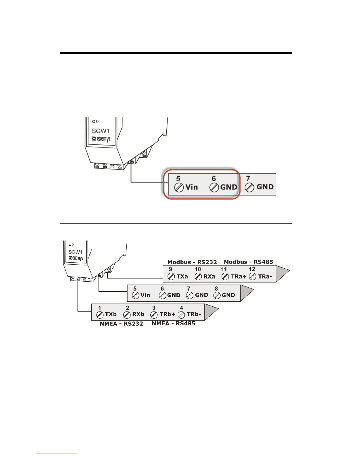
2.1 Power S pply connection
The SGW1-IA3-MB-NM accepts a power supply in the range of +1 to 3 VDC. The positive
must be connected to terminal #5 and the negative to terminal #6, as can be seen in the
following image:
2.2 Serial Ports Connections
RS232 ports are DTE type. That means, data is transmitted through the TX terminal and is
received on the RX terminal. If you want to connect another DTE device you must cross the Tx
and Rx terminals.
2.3 Led Indicators
The SGW1-IA3-MB-NM has three LED indicators. One of them indicates that the device is
energized (Power). While the other two are each linked to the activity on the serial ports -
Modbus (A) and NMEA (B).

SGW1-IA3-MB-NM – NMEA talker to Modbus slave Converter – User’s Manual
www exemys com Rev 2 7
3Config ration
The SGW1-IA3-MB-NM provides a command console for configuration via USB port.
To access it, the SGW1-IA3-MB-NM must be connected to a USB port on a PC and it must
have the Exemys branded terminal program called Exemys Console.
The driver for the USB can be downloaded from here: www.exemys.com/rmsrmdriver
The terminal type program can be downloaded from here: www.exemys.com/console
Once the driver and the terminal type program have been installed, the terminal must be run,
connect the SGW1-IA3- MB-NM to a USB port on the PC and go to the Connection -> USB
menu, a window will open with the description of all the Exemys products with USB found.
Select with double click the product to be configured and pressing ENTER will show a ">"
sign indicating that you can enter the configuration commands listed below.

SGW1-IA3-MB-NM – NMEA talker to Modbus slave Converter – User’s Manual
www exemys com Rev 2 8
3.1 Modb s Config ration.
Com
m
and
Descrip
tio
n
MB
MBMB
MBBAUD
BAUD BAUD
BAUD
(12 |…|1152 )
Modbus Port Baud rate
•Values: 12 , 24 , 48 , 96 , 144 , 192 , 288 , 384 , 576 or 1152 .
Example: MBBAUD:115200
MB
MBMB
MBBITS
BITSBITS
BITS
(7|8)
Modbus port stop bits. 7 bits can only be selected, when the "PROTOCOL" is Modbus ASCII.
•Values: 7 or 8
Example: MBBITS:8
MB
MBMB
MBPARITY
PARITYPARITY
PARITY
(N|E|O)
Modbus Port Parity.
•N
NN
N = without parity / E
EE
E = Even parity / O
OO
O = Odd parity
Exmple: MBPARITY:E
MB
MBMB
MBSTOP
STOPSTOP
STOP
(1|2)
Modbus Port Stop Bits
•Values: 1 or 2
Example: MBSTOP:2
MB
MBMB
MBPROTOCOL
PROTOCOLPROTOCOL
PROTOCOL
(R|A)
Modbus type
•R
RR
R = Modbus RTU / A =
A = A =
A = Modbus ASCII
Example: MBPROTOCOL:R
MB
MBMB
MBPKTTOUT
PKTTOUTPKTTOUT
PKTTOUT
(3…5 )
Modbus RTU packet expiration time
•Values: 3 to 5 [byte times]
Example: MBPKTTOUT:4
MB
MBMB
MBEXCEPTION
EXCEPTIONEXCEPTION
EXCEPTION
(E|D)
Modbus port exceptions
•E
EE
E = Enabled / D =
D =D =
D = Disabled
Example: MBEXCEPTION:D
MBID
MBIDMBID
MBID
(1…254)
Modbus slave ID for internal registers memory.
•Values: 1 to 254
Example:
MBID:110
MBEXCEPTION - Enables or disables exceptions for the Modbus Port. If the option is
disabled the SGW1-IA3-MB-NM will respond to errors with silence, otherwise it will
return an exception code.

SGW1-IA3-MB-NM – NMEA talker to Modbus slave Converter – User’s Manual
www exemys com Rev 2 9
MBPKTTOUT -
--
-
Modbus RTU packet expiration time: Modbus RTU packets are
separated from each other by a time interval. This parameter allows you to change the
maximum time, counting after the last byte of the packet, during which the SGW1-IA3-
MB-NM will assume that the packet has not yet been terminated. After this maximum
time, the SGW1-IA3-MB-NM will assume that the packet has finished arriving. The time
is entered in one-byte time units, with a minimum of 3 units. (Don’t change this value
unless you know exactly what it means)
3.2 NMEA Config ration
Com
m
and
Descrip
tion
NMEA
NMEANMEA
NMEABAUD
BAUDBAUD
BAUD
(12 |…|1152 )
NMEA Port Baud rate
•Values: 12 , 24 , 48 , 96 , 144 , 192 , 288 , 384 , 576 ó 1152 .
Example: NMEABAUD:115200
NMEA
NMEANMEA
NMEABITS
BITSBITS
BITS
(7|8)
NMEA Port data bits
•Values: 7 or 8.
Example: NMEABITS:8
NMEA
NMEANMEA
NMEAPARITY
PARITYPARITY
PARITY
(N|E|O)
NMEA Port Parity.
•N
NN
N = NONE / E
EE
E = EVEN / O
OO
O = ODD
Example: NMEAPARITY:E
NMEA
NMEANMEA
NMEASTOP
STOPSTOP
STOP
(1|2)
NMEA Port stop bits
•Values: 1 or 2.
Example: NMEASTOP:1
NMEASEND
NMEASENDNMEASEND
NMEASEND
Sends a message from the USB console directly to the NMEA port.
It can be used to configure the NMEA device in case it’s needed.
Example: NMEASEND:$PGRMO,GPRMC,1
NMEALISTEN
NMEALISTENNMEALISTEN
NMEALISTEN
It configures the SGW1 to the USB console everything that comes from the NMEA port.
It can used to verify the connection to the NMEA talker and see which sentences are
being received
NMEAVERB
NMEAVERBNMEAVERB
NMEAVERB
It configures the SGW1 to send to the USB console details of the NMEA sentences
received on the NMEA port.

SGW1-IA3-MB-NM – NMEA talker to Modbus slave Converter – User’s Manual
www exemys com Rev 2 10
3.3 Other commands
Command Description
LIST
LISTLIST
LIST
Lists the current configuration.
HELP
HELPHELP
HELP
Displays the list of all available commands with syntax and
descriptive text.
FACTRESET
FACTRESETFACTRESET
FACTRESET
Restart the device factory settings.

SGW1-IA3-MB-NM – NMEA talker to Modbus slave Converter – User’s Manual
www exemys com Rev 2 11
4Modb s Registers
The following table shows how to map each NMEA statement in Modbus registers.
If your NMEA talker does not send any of the statements listed here, values will be read out at
.
Notes:
• Where two Modbus registers are indicated to represent a value of 32 bits, the first register
contains the upper part and the second the lower part of the represented value.
• Where clarifications such as "x1 " are specified, it means that the value obtained from the
NMEA device is multiplied by the corresponding factor to achieve a higher degree of
resolution in the indicated value.
• Where "ASCII" is specified, it means that the value read is the numerical representation
according to the ASCII coding of the letter obtained by the device that delivers the NMEA
frame.
• Where "ddmmyyyy" is specified, it means that the value indicated for this case is 2 digits
representing the day, 2 the month and 4 the year. Thus the decimal number 5112 12, refers
to the date November 5, 2 12.
• Where "hhmmss" is specified, it means that the value indicated for this case is 2 digits
representing the hour, 2 minutes and 2 seconds. Thus the decimal number 123 45, refers to
the time 12:3 :45.
• In the registers where Latitude and Longitude are expressed, the arithmetic that must be
done to decode the information is the following:
(SSSS / 36 )) x 1 , ,
Example:
LAT: 48 ° 43'14.9224''N.
LAT: 48 ° 43'14.9224''N.LAT: 48 ° 43'14.9224''N.
LAT: 48 ° 43'14.9224''N.
48 + (43/6 ) + (14.9224 / 36 ) = 48.72 8118 °, then multiply x 1 , , to obtain
exactly the value that is observed in the Modbus register = 487.2 8.117

SGW1-IA3-MB-NM – NMEA talker to Modbus slave Converter – User’s Manual
www exemys com Rev 2 12
GGA Global Positioning System Fixed Data
4 1:2 UTC Time hhmmss -
4 3:4 Latitude x1 , , signed º
4 5:6 Longitude x1 , , signed º
4 7 GPS Quality - -
4 8 Number of Satellites - -
4 9 Horizontal Dilution x1 -
4 1 :11 Altitude x1 meters/feet
4 12 Altitude Unit ASCII -
4 13 Geoidal Separation x1 meters/feet
4 14 Geoidal Separation Units ASCII -
4 15 Age of differential GPS data
x1 Seconds
VTG Course Over Ground and Ground Speed
4 16
True track made good
x1 º
4 17
Magnetic track made good
x1 º
4 18
Ground speed, knots
x1 knots
4 19
Ground speed, Kilometers per hour
x1 kph
MWV Wind Speed and Angle
4 2
Wind angle
x1 º
4 21
Reference
ASCII -
4 22
Wi
nd speed
x1 kph/knots
4 23
Wind speed units
ASCII -
4 24
Status
ASCII -
XDR Transducer Measurement
4 25
Sensor type 1
ASCII -
4 26
Sensor reading 1
x1 -
4 27
Sensor units 1
ASCII -
4 28
Sensor type 2
ASCII -
4 29
Sensor reading 2
x1 -
4 3
Sensor units 1
ASCII -
4 31
Sensor type 3
ASCII -
4 32
Sensor reading 3
x1 -
4 33
Sensor units 3
ASCII -
VHW Water speed and heading
4 34
Degrees True
x1 º
4 35
Degrees Magnetic
x1 º
4 36
Speed
x1 knots
4 37
Speed
x1 kph
ROT Rate Of Turn
4 38 Turn Velocity (*) x1 º per minute
4 39 State ASCII -

SGW1-IA3-MB-NM – NMEA talker to Modbus slave Converter – User’s Manual
www exemys com Rev 2 13
VBW Dual Ground / Water Speed
4 4
Longitudinal water speed (*)
x1 Nudos
4 41
Transverse water s
peed (*)
x1 Nudos
4 42
Status
ASCII -
4 43
Longitudinal ground speed (*)
x1 Nudos
4 44
Transverse ground speed (*)
x1 Nudos
4 45
Status
ASCII -
4 46
Stern longitudinal water speed (*)
x1 Nudos
4 47
Status
ASCII -
4 48
Stern transverse wat
er speed (*)
x1 knots
4 49
Status
ASCII -
DPT Depth
4 5 Water depth x1 meters
4 51 Offset x1 meters
HDM Heading, Magnetic
4 52 Degrees magnetic x1 º
ZDA Time & Date
4 53:54
UTC Time
hhmmss -
4 55:56
UTC Date
ddmmyyyy -
4 57 Hours - hours
4 58 Minutes - minutes
HDT
Heading, True
4 59 Real degrees x1 º
RMC
Recommended Min. Specific GNSS Data
4 6 :61 Time (UTC) hhmmss -
4 62 Status ASCII -
4 63:64 Latitude x1 , , signed º
4 65:66 Longitude x1 , , signed º
4 67 Speed over ground x1 knots
4 68 Track made good x1 º
4 69:7 Date (UTC) ddmmyy -
4 71 Magnetic variation x1 º
4 72 Variation ASCII -
4 73 Mode ASCII -
RMB Recommended Min. Navigation Information
4 74 Status ASCII -
4 75 Cross Track Error x1 miles
4 76 Course ASCII -
4 77:78 Destination Waypoint Latitude x1 , , signed º
4 79:8 Destination Waypoint Longitude x1 , , signed º
4 81 Range to destination x1 miles
4 82 Bearing to destination x1 º

SGW1-IA3-MB-NM – NMEA talker to Modbus slave Converter – User’s Manual
www exemys com Rev 2 14
4 83 Destination closing velocity x1 knots
4 84 Arrival Status ASCII -
4 85 Mode ASCII -
APB Autopilot Sentence "B"
4 86 Status 1 ASCII -
4 87 Status 2 ASCII -
4 88 Cross Track Error Magnitude x1 miles
4 89 Direction to steer ASCII -
4 9 Status 3 ASCII -
4 91 Status 4 ASCII -
4 92 Bearing origin to destination x1 º
4 93 Magnetic/True ASCII -
4 94 Bearing, present position to Destination x1 º
4 95 Magnetic/True ASCII -
4 96 Heading to steer to destination waypoint x1
4 97 Magnetic/True ASCII -
4 98 Mode ASCII -
DBT Depth Below Transducer
4 99 Water depth x1 feet
4 1 Water depth x1 Meters
4 1 1 Water depth x1 Fathoms
MTW Water Temperature
4 1 2 Water temperature x1 ºC
MTA Air Temperature
4 1 3 Air temperature x1 ºC
RSA Rudder Sensor Angle
4 1 4
Starboard rudder sensor (*)
x1 º
4 1 5 Status ASCII -
4 1 6
Port Rudder Sensor (*)
x1 º
4 1 7 Status ASCII -
VDO Message type 1 - Position Report
4 1 8 Message type - -
4 1 9 Repeat indicator - -
4 11 :11 User ID - -
4 112 Navigation Status - -
4 113 Rate of turn (ROT) x1 º/min
4 114 Velocity over ground (SOG) x1 knots
4 115 Position accuracy - -
4 116:17 Longitude x1 , , signed º
4 118:19 Latitude x1 , , signed º
4 12 Course over ground (COG) x1 º
4 121 True Heading (HDG) - º

SGW1-IA3-MB-NM – NMEA talker to Modbus slave Converter – User’s Manual
www exemys com Rev 2 15
4 122 Time (UTC) - -
4 123 Receptor Integrity control (RAIM) - -
(*) When a "-" is received from the NMEA device as a value, it will be indicated with the value
9999 on the Modbus map
(**) The spin ratio (ROT) has three values of special character, which are:
• 9999: This value is displayed when there is no information available on this field
• 713: This value is displayed when you are rotating clockwise to more than 5 degrees in 3
seconds
• -713: This value is displayed when you are turning counterclockwise to more than 5
degrees in 3 seconds

SGW1-IA3-MB-NM – NMEA talker to Modbus slave Converter – User’s Manual
www exemys com Rev 2 16
A. Firmware Upgrade
The firmware of the SGW1-MB-NM can be updated in case of new versions with
improvements, by accessing the serial console intended for this purpose.
Connect an RS232 cable as follows between the computer and the SGW1 and follow the
steps below
The terminal console program can be downloaded from here: www.exemys.com/console
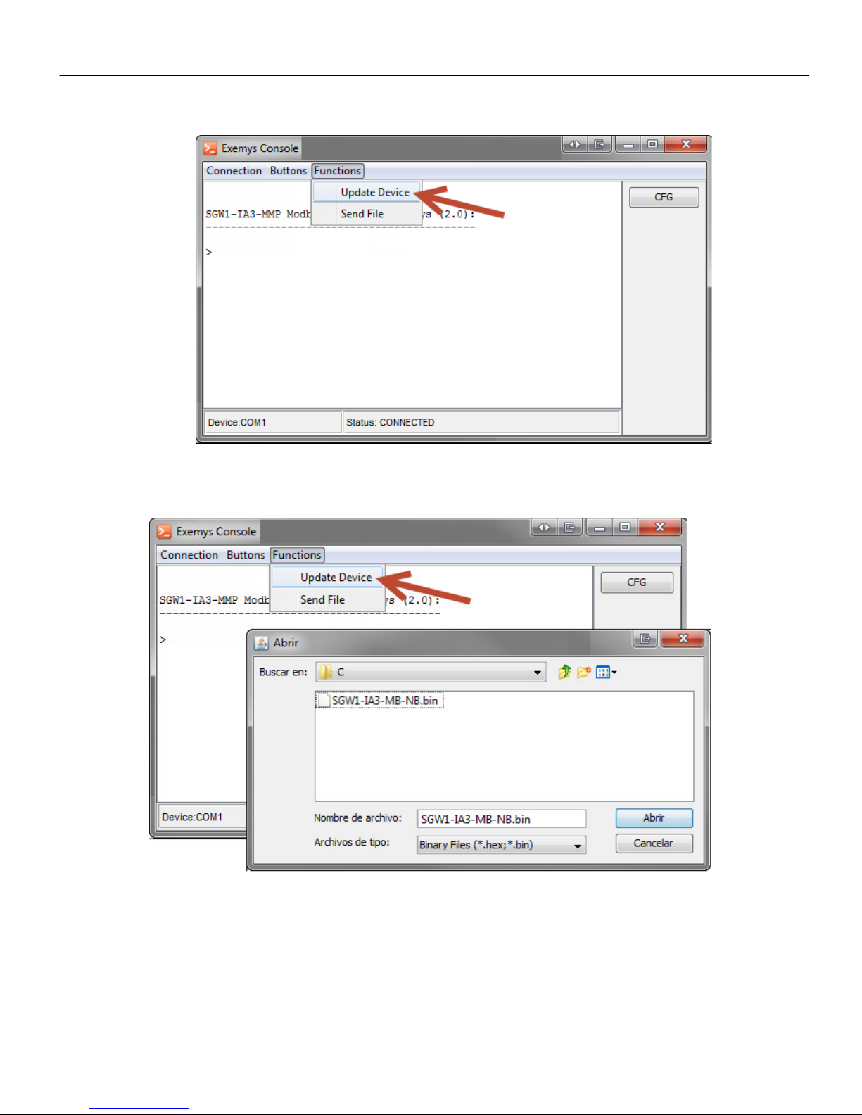
1. Open an Exemys Console terminal type program in the COM of the corresponding
computer and verify in the terminal that the Baudrate is in 96 .
1. Turn on the SGW1 and within the first 7 seconds type CFG and press ENTER or press
the CFG button that is available. After doing it the SGW1 will show the welcome
message:
SGW1-MB-NM NMEA to Modbus converter - Exemys (2.0):
---------------------------------------------------
>
SGW1-IA3-MB-NM – NMEA talker to Modbus slave Converter – User’s Manual
www exemys com Rev 2 17
2. Then go to the menu Functions -> Update Device.
3. Locate and select the binary file (.bin) to be transferred and press the Open button to
start the firmware update of the device.
4. During the file transfer the progress of the process will be displayed.

SGW1-IA3-MB-NM – NMEA talker to Modbus slave Converter – User’s Manual
www exemys com Rev 2 18
5. At the end, the device will be restarted to install the update, preserving the current
configuration.
Do not turn off the device until the "Installed" message is displayed, this can cause a permanent
damage to the device.

SGW1-IA3-MB-NM – NMEA talker to Modbus slave Converter – User’s Manual
www exemys com Rev 2 19
B. Factory settings
Par
a
met
e
r
Val
ue
Modbus
ModbusModbus
Modbus
Port
Port Port
Port
(A)
(A)(A)
(A)
Baud
rate
96
bps
Data bits
8
Parity
NO
Stop
bits
1
Modbus
type
Modbus
RTU
Modbus
slave ID
24
Exceptions
Disabled
Modbus
RTU
packet time
3
byte
s time
Port
Port Port
Port
NMEA (B)
NMEA (B)NMEA (B)
NMEA (B)
Baud
rate
96
bps
Data bits
8
Parity
NO
Stop
bits
1
SGW1-IA3-MB-NM – NMEA talker to Modbus slave Converter – User’s Manual
www exemys com Rev 2 20
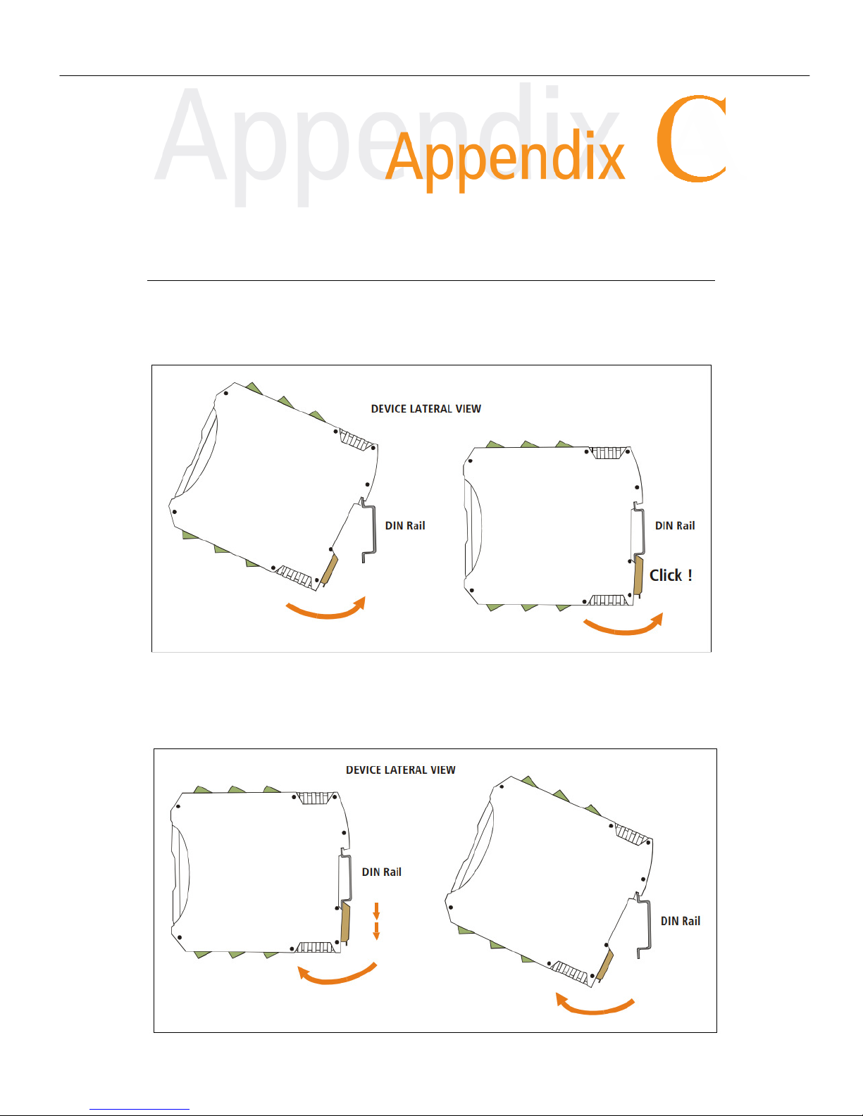
C. DIN Rail mo nt
The equipment can be DIN rail mounted. To attach the module to the rail, point the top of
the device toward it and locate the adapter slot on its top edge. Press firmly onto the rail
until it clicks into place (a click will be heard when attaching the module to the DIN rail)
To remove the rail module, first remove the input terminals. Then insert a screwdriver into
the lower lock of the device's DIN connector and force the connector down until the module
disengages.
Other manuals for SGW1-MB-NM
1
Table of contents
Other exemys Media Converter manuals


 user guide")


