Individual Computers Keyrah v3 User manual
Keyrah v3
User Manual
21/04/23
1

Content
1. Content
1. Content.............................................................................................................................................2
2. Introduction......................................................................................................................................3
3. Using Keyrah V3..............................................................................................................................5
3.1 Keyboards..................................................................................................................................5
3.1.1 Matri Connectors..............................................................................................................5
3.1.2 Serial Connectors...............................................................................................................5
3.1.3 PS/2 Connector..................................................................................................................5
3.1.4 DB25 Connector................................................................................................................5
3.1.5 Locking Keys.....................................................................................................................6
3.2 LEDs..........................................................................................................................................7
3.2.1 Connectors.........................................................................................................................7
3.2.2 Power LED.........................................................................................................................7
3.2.3 Keyboard status LEDs.......................................................................................................7
3.3 Joystick Ports.............................................................................................................................8
3.4 Power Switch.............................................................................................................................9
3.5 E tra Buttons.............................................................................................................................9
3.6 Jumpers....................................................................................................................................10
3.6.1 Keymap select..................................................................................................................10
3.6.2 Keyboard type..................................................................................................................10
3.7 Keyboard Mapping..................................................................................................................11
3.7.1 VIC20, C64......................................................................................................................12
Fn E tra Key Layer..............................................................................................................14
3.7.2 C128.................................................................................................................................16
3.7.3 C16...................................................................................................................................17
Fn E tra Key Layer..............................................................................................................18
3.7.4 Amiga...............................................................................................................................20
Fn E tra Key Layer..............................................................................................................20
3.7.5 Atari ST............................................................................................................................22
Fn E tra Key Layer..............................................................................................................23
3.8 Using a custom Keymap..........................................................................................................25
3.8.1 Keyboard Matri ..............................................................................................................26
CBM Keyboards...................................................................................................................26
Amiga Keyboards.................................................................................................................27
Atari Keyboards...................................................................................................................28
PC Keyboards.......................................................................................................................29
3.8.2 Global e tra Keys.............................................................................................................30
3.8.3 Configuration Data...........................................................................................................30
4. Appendi .........................................................................................................................................31
4.1 Pinouts.....................................................................................................................................31
4.1.1 DE9 Connectors...............................................................................................................31
4.1.2 DB25 Connector..............................................................................................................32
4.2 Technical Data.........................................................................................................................33
5. Credits.............................................................................................................................................34
6. Fine print........................................................................................................................................35
2

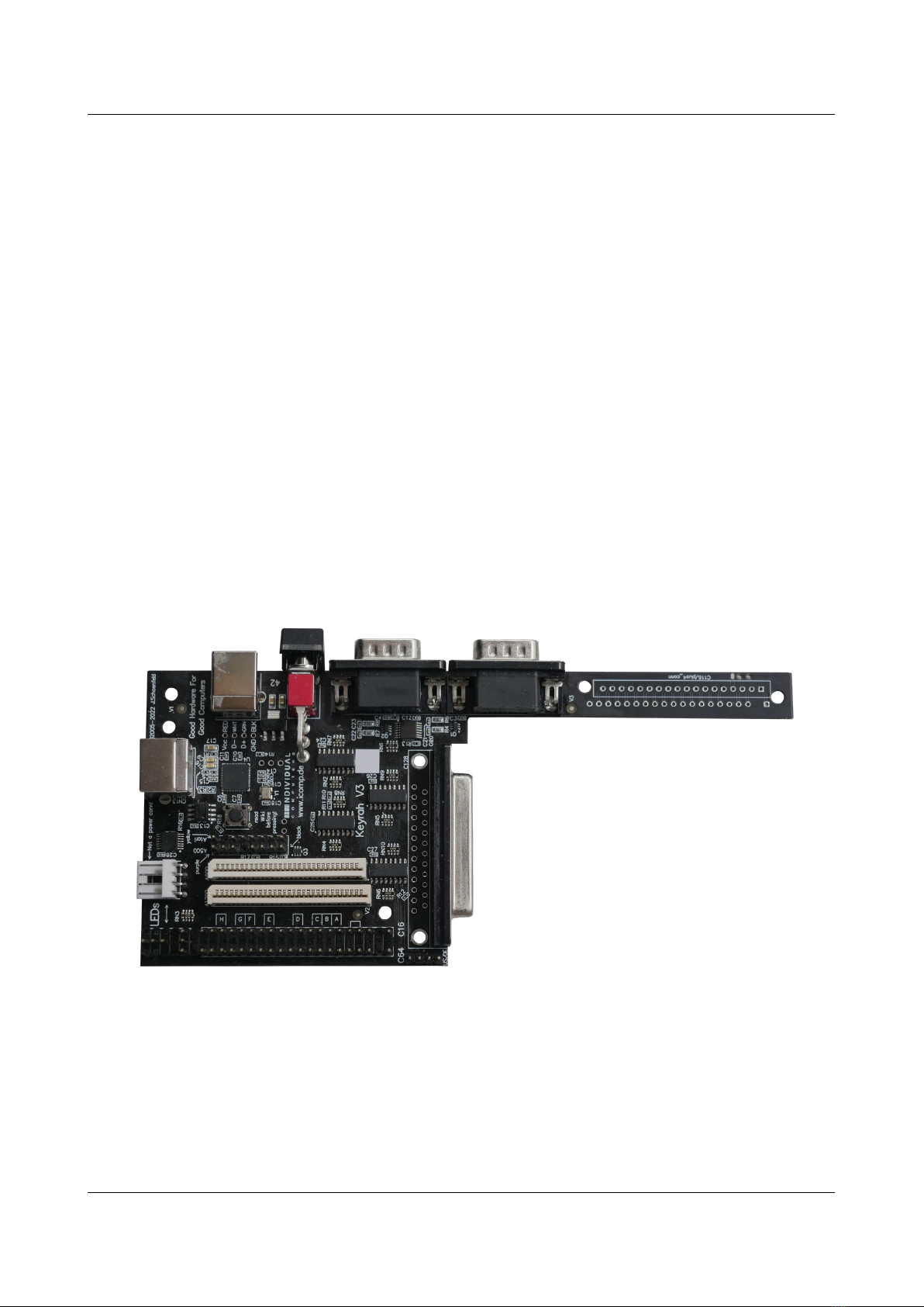
Introduction
2. Introduction
Thank you for purchasing an individual Computers product. It is important to read the following
instructions carefully before attempting installation. Individual Computers cannot be held
responsible for any damage caused due to incorrect installation.
Before installing Keyrah in the case of a C128, C64, VIC-20 or C-16, please remove the mainboard
of the old computer. Use the screws of the mainboard to mount Keyrah. Older "breadbo “ models
of the C64 and the VIC-20 also have a metal bracket on the side of the mainboard that should be
mounted on Keyrah.
Connect the keyboard to the connector that's labelled with the type of your computer. The
orientation of the cable is determined by a missing pin ("key pin") in the connector.
Keyrah should not be used without a case.
For connection to a computer, use a USB type-b to type-a cable of your choice. If you're making a
special case with Keyrah and a computer mainboard in the same casing, you can also use the
internal USB-connector. The pinout is printed on the board itself, including the colours that are
usually used for internal USB cabling. You can only use one of the two USB-connections!
You do not need special drivers for using Keyrah on an Amiga, Mac or PC. Just plug it in, and
driver installation will happen automatically.
Attaching and detaching Keyrah can be done without shutting down the machine (so-called hot-
plugging) – however do not attach or detach it when the host computer is currently in sleep mode.
Changing the switch position can also be done while the computer is in use, re-starting the machine
is not necessary.
Technical hints
Keyrah is a USB-only device. Connection to a PS/2 port with an adapter is not possible.
The connector for A600 LEDs is e actly the same as the power connector for 3.5“ floppy drives.
You must not connect any power here! Commodore's choice for this connector is surely a bad one,
but we want to keep Keyrah as easy to install as possible, so we've kept the connector shape. We
trust that you believe us that Keyrah works fine without additional power!
Please only connect the devices mentioned in 3.1 Keyboards and 3.3 Joystick Ports.
3
Using Keyrah V3
3. Using Keyrah V3
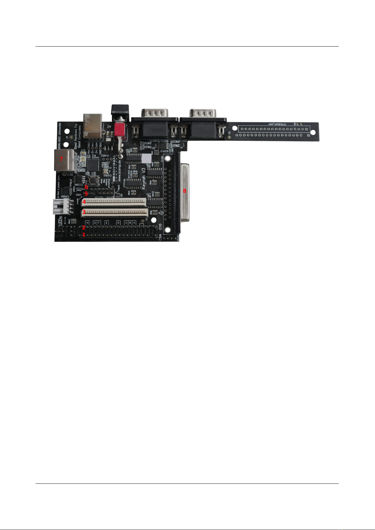
3.1 Keyboards
3.1.1 Matrix Connectors
Some keyboards can be connected to one of the matri connectors on the Keyrah v3 board:
•(1) VIC20, C64
•(2) C16
•(3) Amiga 1200
•(4) Amiga 600
3.1.2 Serial Connectors
•(5) Amiga 500, Amiga 2000
•(6) Atari ST
3.1.3 PS 2 Connector
(7) The PS/2 connector can be used for these keyboards:
•Amiga 4000,
•Amiga 2000, A3000 via DIN to PS/2 Adapter
•PC (AT) via DIN to PS/2 Adapter
•PC (XT) via DIN to PS/2 Adapter
•PS/2
4

Using Keyrah V3
3.1.4 DB25 Connector
(8) The DB25 connector can be used for these keyboards:
•C128D
•SX64 (requires a simple 1:1 Adapter/Cable)
•PET (requires a passive Adapter)
•CBM2 (requires an active Adapter)
3.1.5 Locking Keys
In a modern PC Keyboard layout there are three keys that will toggle a state on and off permanently
rather than just producing an down/up event – „CAPS lock“, „NUM lock“ and „Scroll lock“. Their
current state is usually indicated by an LED. However, on some of the keyboards that can be used
with Keyrah V3, the equivalent keys are either actual mechanically locking keys (eg the CBM
keyboards have a mechanical shift-lock key) or the keyboard manages the state of the LEDs on its
own and there is no way to modify that state (like with PC/XT keyboards). For those keyboards
specific code was added that makes sure the state of those keys is always in sync with a second
keyboard connected to the same host. If the state of the keyboard can not be modified, the host
keyboard status follows Keyrah.
•CBM Keyboards have a mechanically locking shift-lock key. Keyrah will do two things:
◦when it is pressed, remove the left shift key from the matri , so only „CAPS lock“ is
being reported as pressed.
◦when the remote caps lock status does not match the state of the shift-lock key, Keyrah
will generate e tra „CAPS lock“ keypresses to make sure the remote status changes
accordingly.
•PC/XT Keyboards have the usual three LEDs, however there is no way to modify their
status. So when the remote status does not match the state of the “CAPS lock”, “NUM lock”
or “Scroll lock” LEDs, Keyrah will generate e tra keypresses to make sure the remote status
changes accordingly.
•Amiga 500 Keyboards (with serial interface) have a “CAPS lock” LED, but manage its state
by itself and there is no way to modify its status. When the remote caps lock status does not
match the state of the caps-lock LED, Keyrah will generate e tra „CAPS lock“ keypresses
to make sure the remote status changes accordingly.
5
Using Keyrah V3
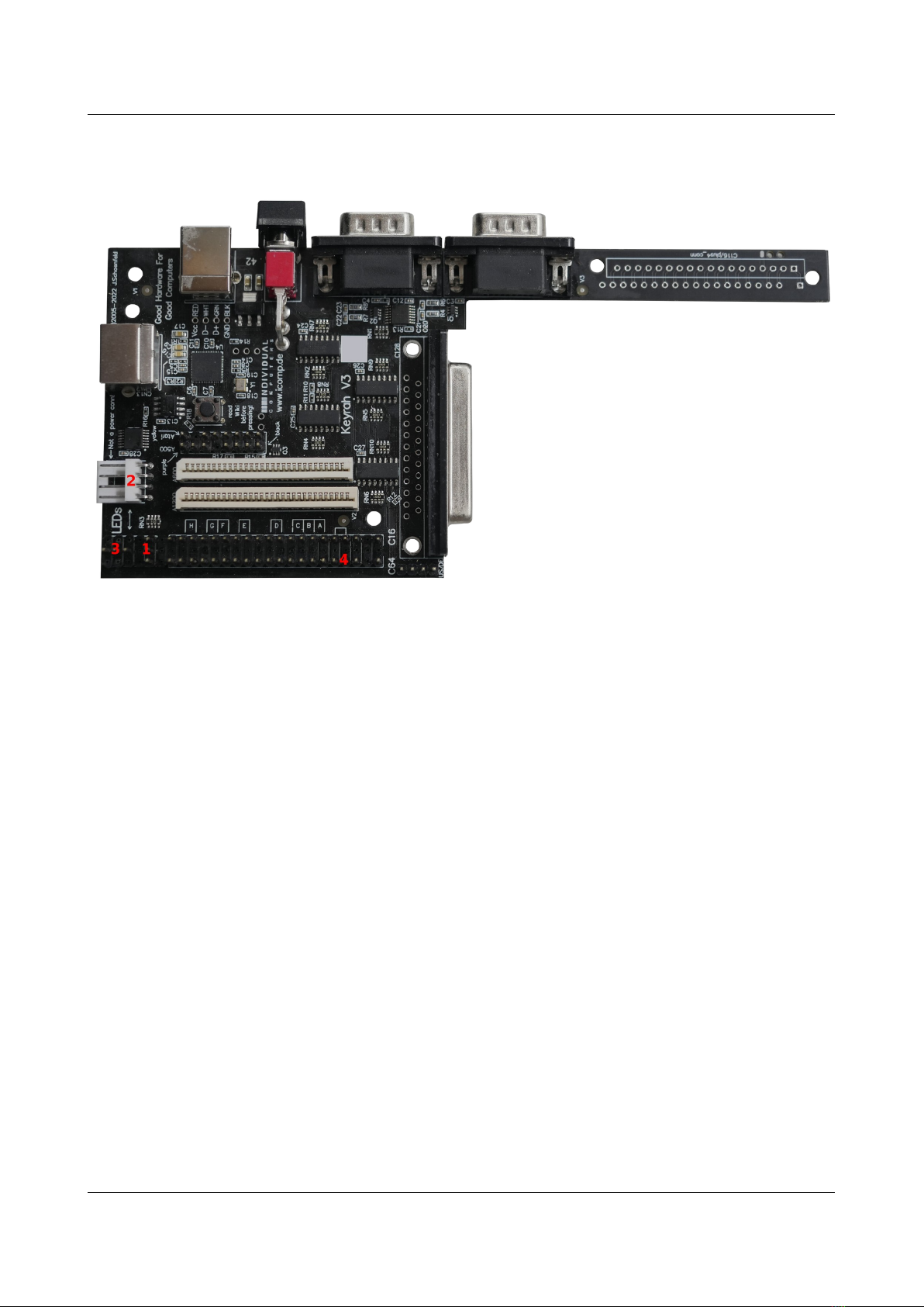
3.2 LEDs
3.2.1 Connectors
There are two types of LED connectors
(1) The „C64 Style“ 3 Pin LED Connector ne t to the keyboard connector. The middle Pin is GND,
the pin facing the edge of the board is the Power LED, the pin facing away from the edge is the
Num Lock LED.
These two are the only LEDs that can be directly connected without an additional Resistor!
Since the C128 has the LED on a very short cable, you will have to use an e tender, which is not
included in this package.
(2) The „Amiga 600 Style“ 4 Pin connector.
(3) The „Amiga 1200 Style“ 4 Pin connector (shares the middle pin of the C64 connector).
The miga-LED connectors have no resistors in the circuit, so the voltage is too high for an
"LED only" cable, you MUST use current limiting resistors or you risk damaging the
hardware!
(4) E tra LED on the C64 keyboard connector (see below),
You MUST use a current limiting resistor in series with the extra LED, or you risk damaging
the Hardware!
6

Using Keyrah V3
3.2.2 Power LED
The Power LED shows one of three states:
•Blinking. This means the device is in pre-initializing state. If it stays in this state then a
power cycle is needed.
•Fading on and off. This means the device has been suspended. It might be possible to wake
it up by pressing any key.
•On. Device is ready :)
3.2.3 Keyboard status LEDs
Two keyboard status LEDs are available at the e ternal connectors – „Num Lock“ and „Scroll
Lock“. Generally those will indicate the status their names imply, with the following e ceptions:
•The „Num Lock“ LED output can not be used with keyboards that have a serial interface:
Amiga 500, Atari ST, PS/2, PC/XT
•When using a CBM keyboard, the „Scroll Lock“ LED will show the CAPS lock status –
e cept when using a SX64 Keyboard (which has a shiftlock LED).
•When using an Amiga 500 Keyboard, the „Drive“ LED will show the „Num Lock“ Status.
•When using an Atari ST Keyboard, the LED on the Keyboard will show the CAPS lock
status. Unfortunately the „Num Lock“ and „Scroll Lock“ LEDs can not be used with this
keyboard.
3.2.4 Extra LED
Note that this pin was originally only intended for testing, directly goes to a I/O pin of the
CPU and is completely unprotected. Its use is not recommended nor supported – if you don’t
know what that means skip the following paragraph and do NOT use it.
One e tra LED can be connected between Pin 4 of the C64 keyboard connector and GND (for
e ample Pin 1 of the C64 keyboard connector), depending on the keyboard in use it will show one
of the following:
•Caps-Lock when an SX64, PC/XT or PS/2 Keyboard is used.
•Num-Lock when an Atari ST Keyboard is used.
•Scroll-Lock when an Amiga 500, C64, C16, C128, CBM2 or PET (via DB25 Adapter)
Keyboard is used.
The e tra LED can NOT be used with a C64 or Amiga 1200 keyboard.
Remember that you MUST use at least a current limiting resistor in series, preferably a driver
IC, with the LED, or you WILL damage the Hardware!
7
Using Keyrah V3
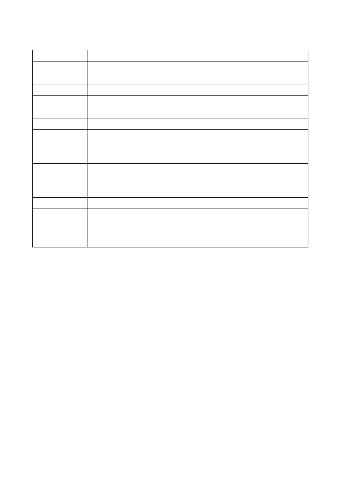
3.2.5 Overview
Keyboard Keyboard LEDs Scroll-lock LED (1) Num-lock LED (2) Extra LED
Amiga 500 Caps / Num Num - / - Scroll
Amiga 1200 Caps Scroll Num - / -
Atari ST Caps - / - - / - Num
C64 - / - Caps Num - / -
C16 - / - Caps Num Scroll
C128 - / - Caps Num Scroll
SX64 Caps Scroll Num Caps
PC XT Num / Caps / Scroll Scroll - / - Caps
PC AT Num / Caps / Scroll Scroll - / - Caps
CBM2 / 7 0 - / - Caps Num Scroll
PET / 8296 - / - Caps Num Scroll
*1) Amiga Floppy LED (labelled “F.Disk” on A1200)
*2) Amiga Harddisk LED (labelled “Disk” on A600)
8

Using Keyrah V3
3.3 Joystick Ports
Each Joystick Port will appear as a separate HID game controller.
(1) The connector further from the power switch is “Port 1”
(2) The connector ne t to the power switch is “Port 2”
The following devices are currently supported:
•Standard DE9 joysticks
◦The directions are mapped to the 1st and 2nd controller a is.
◦The button is mapped to the 1st controller button.
◦Additionally “C64 GS Style” 2nd and 3rd joystick button (connected between POTX/Y
and VCC) will be mapped to 2nd and 3rd controller button
•Standard “Commodore” paddles (470 kOhm)
◦The paddles are mapped to the 3rd and 4th controller a is.
◦Note that the paddle buttons will appear as “left” and “right” just like on a C64
9
Using Keyrah V3
3.4 Buttons
3.4.1 Power Switch
(1) The Power switch has three functions:
1. Bottom („off“) and middle („on“) position toggles between alternative keymaps (see 3.6
Keyboard Mapping
2. Press and release top momentary switch to trigger a keypress (by default mapped to the key
that brings up the menu and/or disables input capturing in the respective supported
emulator).
3. Press and hold top momentary switch (for appro 2 seconds) to put the host into sleep mode.
Keyrah is programmed to wake the computer up on any keystroke if it was switched off using the
ACPI key. This can of course only work if the USB port is supplied with power while the PC is in
standby mode, and your BIOS is properly configured.
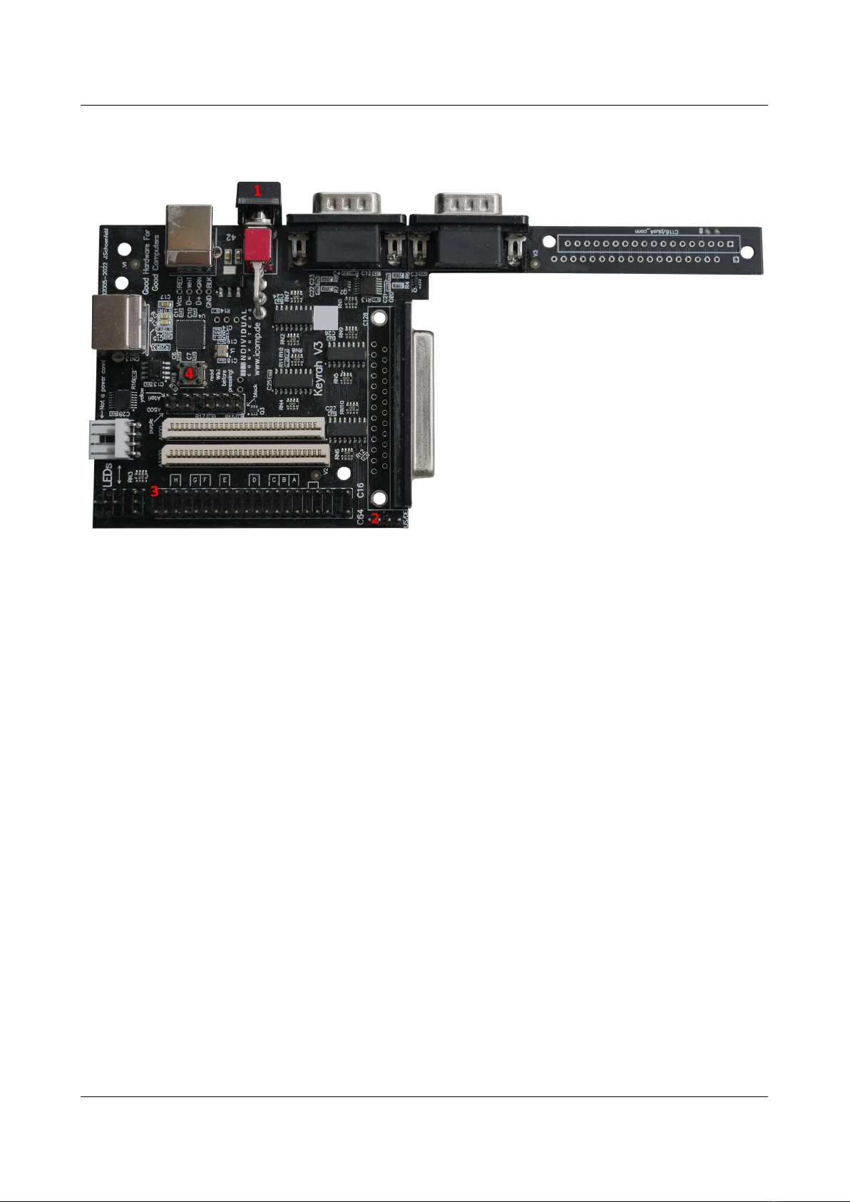
3.4.2 Extra Buttons
•(2) One e tra Button/Key can be connected to the Menu_btn keypad on the board. This
button is by default mapped to the key that brings up the menu and/or disables input
capturing in the respective supported emulator.
•(3) Another e tra Button/Key can be connected between Pin 20 of the C16 connector and
GND (eg Pin 4 of the C16 connector). This button can not be used with a C16 or Amiga
keyboard. By default this is mapped to the Escape key.
10
Using Keyrah V3
3.4.3 Boot Button
(4) The boot button has two functions:
•Press the button to “type” the shift-lock ADC value (see Shift-lock threshold)
•To enable mass storage mode for updating the firmware or flashing a keymap, press and
hold the button at power up, or hold the button for about 5 seconds (see 3.7 Using a custom
Keymap).
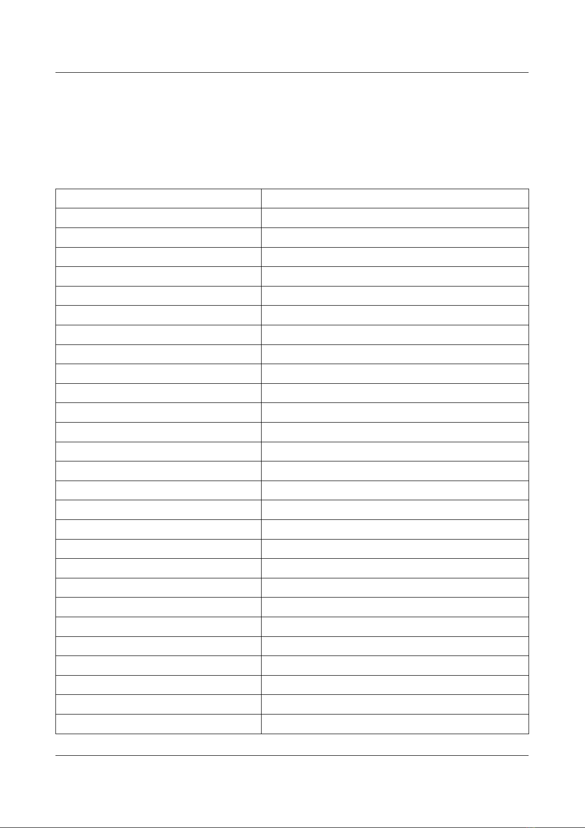
3.4.4 Overview
Keyboard Menu/Power Button Extra Button
Amiga 500 F12 - / -
Amiga 1200 F12 - / -
Atari ST Pause Escape
C64 F12 Escape
C16 F12 - / -
C128 F12 Escape
SX64 F12 Escape
PC XT F12 Escape
PC AT F12 Escape
CBM2 / 7 0 F12 Escape
PET / 8296 F12 Escape
11
Using Keyrah V3
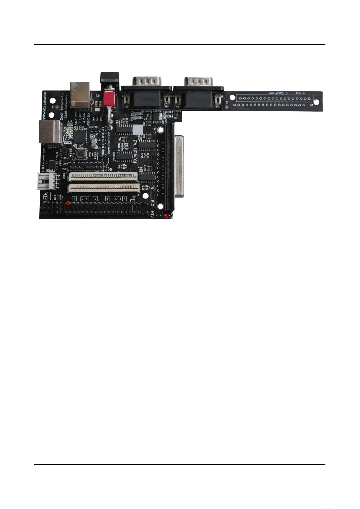
3.5 Jumpers
3.5.1 Keymap select
(1) The jumper marked EN/DE selects an alternative keymap (see 3.6 Keyboard Mapping). When
the Jumper is closed the german keymap is selected, when it is open the english keymap is selected.
3.5.2 Keyboard type
(2) Since not every keyboard can be automatically detected, the type can be forced by putting
jumpers on the C16 connector:
20 | o |
19 | o | \ Jumper Pos H
18 | o | /
17 | o | \ Jumper Pos G
16 | o | \ / Jumper Pos F
15 | o | /
14 | o | \ Jumper Pos E
13 | o | /
12 | o |
11 | o | \ Jumper Pos D
10 | o | /
9 | o | \ Jumper Pos C
8 | o | / \ Jumper Pos B
7 | o | \ / Jumper Pos A
6 | o | /
5 | o | \ Jumper Manual keyboard select”
4 | o | /
3 | o |
2 | |
1 | o |
12

Using Keyrah V3
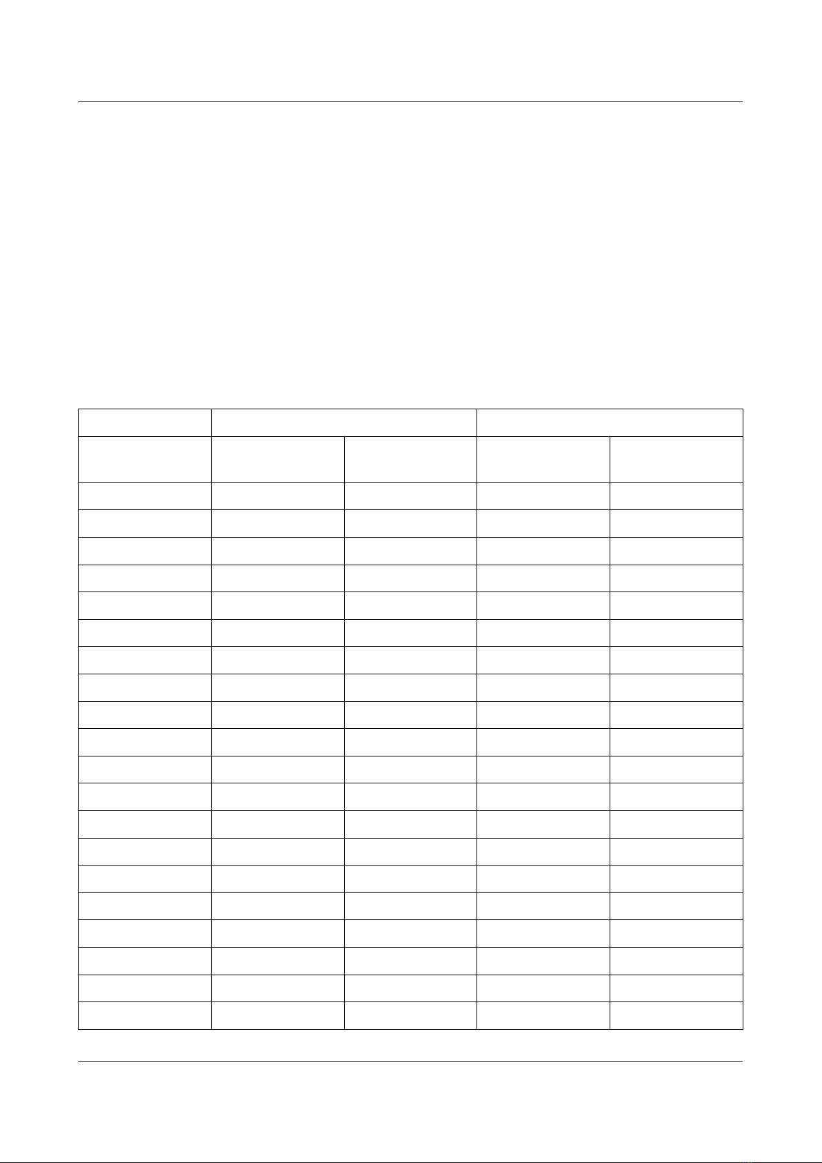
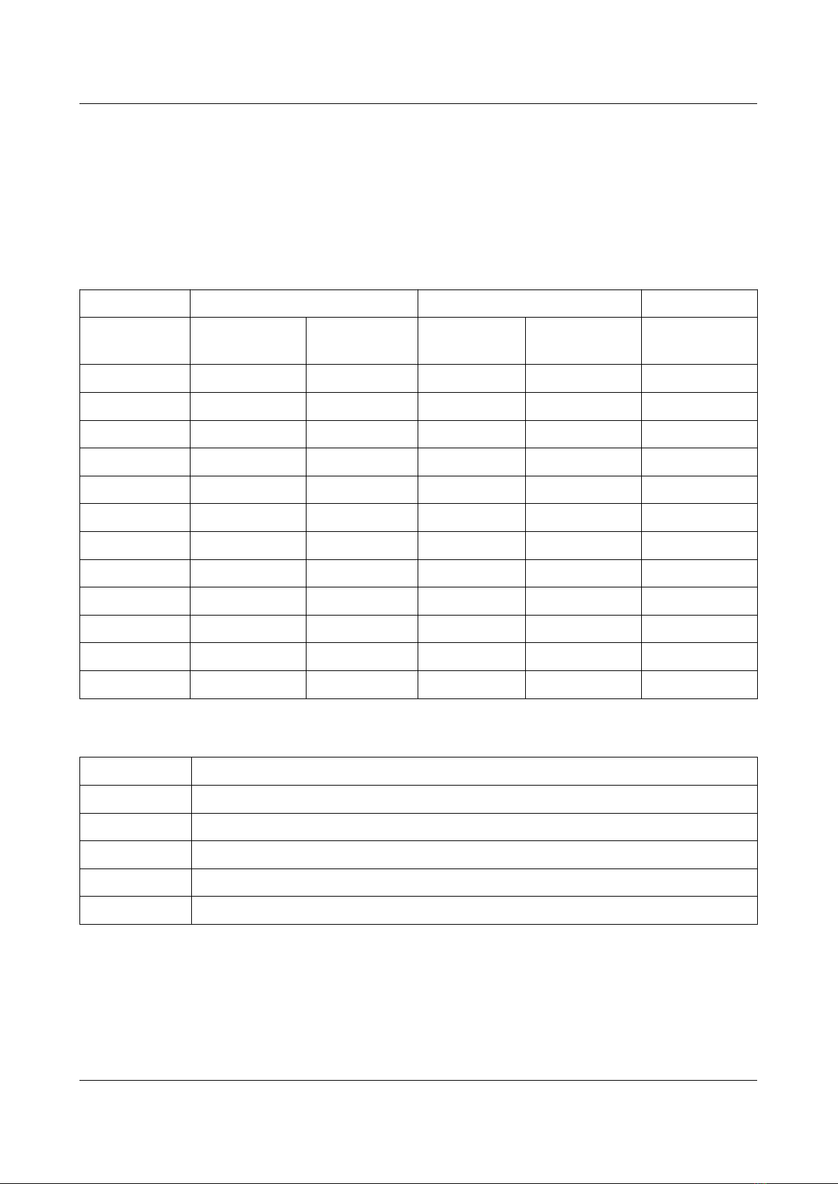
The following keyboards can be selected with jumpers on the C16 pin header. Note that the
“Manual Keyboard select” jumper (5 – 4) must be set for any jumpers to be detected.
Mode Jumper Pins
PS/2 Pos H 19 - 18 5 - 4
Atari ST Pos F 16 - 15 5 - 4
PC XT Pos E 14 - 13 5 - 4
SX64 Pos A 7 - 6 5 - 4
13

Using Keyrah V3
3.6 Keyboard Mapping
Generally for all keyboards one of four keymaps can be selected. This is done by using the “power”
switch and the EN/DE jumper.
The “power” switch switches between a “normal” and a “emulator” keymap:
•When the switch is in “off” (down) position, a key mapping is used which is optimized for
regular PC work. In this mode additional e tra layers via a “Fn” and/or right shift key are
available.
•When the switch is in “on” (up) position, a key mapping is used which is optimized for
being used with an emulator. In particular no e tra virtual layers are applied. Unless there is
a good reason not to, this setting will also stick to the same mapping that Keyrah V2 used in
emulator mode.
The EN/DE jumper switches between what kind of keyboard layout the Keyrah pretends to be
(english or german). This is for the most part relevant for the CBM keyboards.
•When the Jumper is closed the german keymap is selected
•When the Jumper is open the english keymap is selected.
14
Using Keyrah V3
3.6.1 VIC20, C64
For switch position "on" (up), an adapted keyboard layout for C64/VIC-20 is chosen that's perfectly
suitable for the emulator "VICE" (use “positional” keymap).
For switch position "off" (down), the keyboard layout is adapted for use under the Windows
operating system. Most keys have the function that's printed on them, that's why we're only listing
the keys here that differ from their print.
In this setting also some keys are mapped differently in combination with the right shift key – that
eg makes the cursor keys work.
Note that in most operating systems the left ALT key (ALT gr) can be simulated by pressing (and
holding) ALT, then CTRL.
C64/VIC20 Key US layout DE layout
Switch down
(normal)
Switch up
(emulator)
Switch down
(normal)
Switch up
(emulator)
Arrow left Escape ` and ~ Escape ^ and °
+ = and + - and _ ß and ? ß and ?
- - and _ = and + ´ and ` ´ and `
Pound ` and ~ \ and | < and > < and >
CLR/HOME Home Home Home Home
Inst/del Backspace Backspace Backspace Backspace
CTRL Control TAB Control TAB
Y Y Y Z Z
@ \ and | [ and { Ü Ü
* ; and : ] and } + and * + and *
Arrow up Page down End ^ and ° End
RESTORE TAB Page up TAB Page up
RUN/STOP Fn Escape Fn Escape
Shift/Lock (*1) CAPS lock CAPS lock CAPS lock CAPS lock
: / [ [ and { ; and : Ö Ö
; / ] ] and } ' and " Ä Ä
= ' and " Page down # and ' # and '
CBM left ALT Control left ALT Control
Left Shift Left Shift Left Shift Left Shift Left Shift
Z Z Z Y Y
15
Using Keyrah V3
, / < , and < , and < , and ; , and ;
. / > . and > . and > . and : . and :
/ ? / and ? / and ? - and _ - and _
Right Shift (*2) Right Shift Right Shift Right Shift Right Shift
Cursor U/D Down Down Down Down
Cursor L/R Right Right Right Right
F1 F1 F1 F1 F1
F3 F3 F3 F3 F3
F5 F5 F5 F5 F5
F7 F7 F7 F7 F7
Right Shift+F1 F2 Shift+F1 F2 Shift+F1
Right Shift+F3 F4 Shift+F3 F4 Shift+F3
Right Shift+F5 F6 Shift+F5 F6 Shift+F5
Right Shift+F7 F8 Shift+F7 F8 Shift+F7
Right
Shift+Cursor U/D
Up Shift+Down Up Shift+Down
Right
Shift+Cursor L/R
Left Shift+Right Left Shift+Right
*1) Shift lock will produce a “CAPS lock” event. However, due to how CBM Keyboards work, the
left Shift key is always detected as pressed when shift lock is pressed – because of this Keyrah will
always remove “left Shift” from the Keyboard Matri when it detects “Shift Lock”.
*2) When “normal” mapping is active, the right Shift key enables e tra translation for the cursor-
and f-keys (see above)
16
Using Keyrah V3
Fn Extra Key Layer
When the “power” switch is in “off” (down) position, an e tra layer of keys, like on other
“reduced” keyboard layouts, can be enabled by pressing the “Fn” key – which in this case is the
“run/stop” key.
So press and hold the “run/stop” Key, and then press one of the following keys:
C64 Key Extra Key
W Up
A Left
S Down
D Right
4 PrntScr/SysReq
5 Scroll lock
6 Pause/Break
R Insert
T Home
Y Page up
F Delete
G End
H Page down
7 NumLock
8 NP /
9 NP *
0 NP -
U NP 7
I NP 8
O NP 9
P NP +
J NP 4
K NP 5
L NP 6
: NP ,
Return NP Enter
M NP 1
17

Using Keyrah V3
C64 Key Extra Key
W Up
, NP 2
. NP 3
/ NP 0
F1 F9
F3 F10
F5 F11
F7 F12
18
Using Keyrah V3
3.6.2 C128
The C128 keyboard is a C64 keyboard (see above) with 26 e tra keys.
To use the C128 keyboard in VICE, use the Keyrah V3 specific keymap that is provided with VICE
– without that a handful keys will not work as e pected, in particular the “locking” keys.
12 e tra keys at the top of the keyboard:
C128-key US layout DE layout
Switch down
(normal)
Switch up
(emulator)
Switch down
(normal)
Switch up
(emulator)
ESC ESC F9 ESC F9
TAB TAB F10 TAB F10
ALT right ALT F11 right ALT F11
Ascii/DIN caps-lock F12 caps-lock F12 Locking Key
HELP Numlock F2 Numlock F2
Linefeed end F6 end F6
40/80 disp F8 F4 F8 F4 Locking Key
NoScroll scroll lock F8 scroll lock F8
Arrow Up Cursor Up Cursor Up Cursor Up Cursor Up
Arrow Down Cursor Down Insert Cursor Down Insert
Arrow Left Cursor Left Cursor Left Cursor Left Cursor Left
Arrow Right Cursor Right Delete Cursor Right Delete
14 e tra keys on the Numblock:
C128-key Mapped Key
0 … 9 NP 0 … 9
+ NP Add
- NP Substract
Enter NP Return
, NP Decimal
To use the Numblock in VICE, disable the “Allow keyset joysticks” setting
19

Using Keyrah V3
3.6.3 C16
For switch position "on" (up), the layout for C16 keyboards is adapted to the emulator "VICE"
(select “positional” keymap).
C16 Key US layout DE layout
Switch down
(normal)
Switch up
(emulator)
Switch down
(normal)
Switch up
(emulator)
Escape Escape ` and ~ Escape ^ and °
Inst/del Backspace Backspace Backspace Backspace
CTRL Control TAB Control TAB
Y Y Y Z Z
CLR/HOME TAB Home TAB Home
@ ; and : [ and { Ü Ü
+ = and + - and _ + and * ẞ and ?
- - and _ = and + ẞ and ? ´ and `
RUN/STOP Fn Ecape Fn Escape
Z Z Z Y Y
: / [ [ and { ; Ö Ö
; / ] ] and } ' and " Ä Ä
* ‘ and “ Delete # and ' # and '
CBM left ALT left Control left ALT left Control
, / < , and < , and < , and ; , and ;
. / > . and > . and > . and : . and :
/ ? / and ? / and ? - and _ - and _
Pound ` and ~ Delete ^ and ° + and *
= \ and | Insert < and > < and >
F1 F1 F1 F1 F1
F2 F2 F2 F2 F2
F3 F3 F3 F3 F3
HELP F8 F8 F8 F8
20
Other manuals for Keyrah v3
1
Table of contents
Other Individual Computers Recording Equipment manuals


