Industrial Data Systems IDS 440 User manual

IDS 440
Weigh Scale Indicator
Installation/Calibration/Operation
Version 4.2 10/3/2001
Program S440012x
Industrial Data Systems, Inc.
590 W. Freedom Ave. Orange, CA 92865-2530
714-921-9212 Fax 714-998-8656
www.industrialdata.com

Table of Contents
Introduction.........................................................................................................1
What’s In Each Section ..............................................................................................................2
WARRANTY INFORMATION ....................................................................................................3
General Description............................................................................................4
IDS440 Display and Keyboard Diagram ....................................................................................4
The IDS440 Display ...................................................................................................................5
The IDS440 Keyboard................................................................................................................5
Numeric Keypad ..................................................................................................................5
Function Keys ......................................................................................................................5
Control Keys ........................................................................................................................5
Installation and Setup.........................................................................................6
Unpacking the IDS440 ...............................................................................................................6
Item check list ......................................................................................................................6
Installation Guide .......................................................................................................................7
Connect IDS440 to load cell ................................................................................................7
Connect IDS440 to the printer (optional) ............................................................................7
Apply AC Power to the IDS440 ...........................................................................................7
Setup Guide ...............................................................................................................................9
Initialize to Factory Defaults ................................................................................................9
Setup & "Quick" Calibration Guide ......................................................................................9
Calibrate the Weight Indicator .............................................................................................9
Using the IDS440...............................................................................................10
Keyboard Layout ......................................................................................................................10
Operation of Function Keys .....................................................................................................10
Zero ...................................................................................................................................10
Tare ...................................................................................................................................11
Gross/Net...........................................................................................................................11
Print ...................................................................................................................................11
F1 and F2 ..........................................................................................................................11
Memory Register Entry......................................................................................................11
Execute a Scale Basic Function ........................................................................................11
Display Time/Date .............................................................................................................11
Built In Application Programs..........................................................................13
#1 Fill to Setpoint...............................................................................................14
Installation ................................................................................................................................14
Setup Parameters: ...................................................................................................................14
Operators Functions.................................................................................................................14
Enter setpoint.....................................................................................................................14
Start fill operation...............................................................................................................14
Stop fill operations .............................................................................................................14
Print Results ......................................................................................................................14
Error Codes .......................................................................................................................14
# 2 Checkweigh: Under/Between/Over ..................................15

Installation ................................................................................................................................15
Operators Functions.................................................................................................................15
Enter setpoint weights .......................................................................................................15
Recalculate ........................................................................................................................15
# 3 Weigh-in / Weigh-out..........................................................................16
Weigh-In ............................................................................................................................16
Weigh-Out..........................................................................................................................16
Print ID’s, Display ID’s, Clear Totals, Erase ID’s...............................................................16
Set Beginning Sequence Number .....................................................................................17
Options ..............................................................................................................................17
Notes .................................................................................................................................17
# 4 Axle Weigh – Short Scale.............................................................18
Installation ................................................................................................................................18
Setup Parameters ....................................................................................................................18
Operators Functions.................................................................................................................18
# 5 Axle Weigh – Long Scale, Unattended ........................19
Installation ................................................................................................................................19
Setup Parameters ....................................................................................................................19
Operators Functions.................................................................................................................19
# 6 ID, Tare, and Total................................................................................20
Enter ID Tare Data ............................................................................................................20
Recall ID and Tare.............................................................................................................20
Print and Total ID...............................................................................................................20
Print ID’s, Display ID’s, Clear Totals, Erase ID’s...............................................................20
Set Beginning Sequence Number .....................................................................................21
Notes .................................................................................................................................21
# 7 Peak Hold Function..............................................................................21
Enable Peak Hold ..............................................................................................................21
Clear Peak Hold Register ..................................................................................................21
Display Peak Weight .........................................................................................................21
Print Peak Weight..............................................................................................................21
Set Operation Parameters................................................................................23
Access Operation Parameters and Parameter Functions .......................................................23
Operation Parameters Reference Tables ................................................................................23
Scale Parameters ..............................................................................................................24
I/O Port Parameters...........................................................................................................24
Display Intensity, Battery, Watchdog Timer ......................................................................25
Fixed Setpoints..................................................................................................................25
Keyboard Events ...............................................................................................................25
Parameter Functions .........................................................................................................26
Scale Parameters.....................................................................................................................27
Parameter 1. Load Cell mv/V (3 mv/v) ..........................................................................27
Parameter 2. Digital Filter (9) .........................................................................................27
Parameter 3. Display Update Rate (1) ............................................................................27
Parameter 4. Motion Detection Delay (6) .......................................................................28
Parameter 5. Motion Detection Band (6)........................................................................28
Parameter 6. Display Blanking During Motion (No Blanking).........................................28
Parameter 7. Zero Tracking Delay (0)............................................................................28
Parameter 8. Zero tracking band (12) ............................................................................28
Parameter 9. Push Button Zero Percent (100)...............................................................29

Parameter 10. Primary Units Type (1 [lb])......................................................................29
Parameter 11. Decimal Point Position (0 [no decimal point]).........................................29
Parameter 12. Count-by (1)............................................................................................29
Parameter 13. Alternate Units Type (2 [kg])...................................................................30
Parameter 14. Alternate Decimal Point (1).....................................................................30
Parameter 15. Alternate Count-by (5) ............................................................................30
Parameter 16. Alt Units Conversion Factor (45,360) .....................................................30
Parameter 17. Full Scale Graduations (10,000).............................................................31
Parameter 18. Overload Graduations (10,200) ..............................................................31
Parameter 19. Deadload Offset........................................................................................31
Parameter 20. Disable Power-On Zero (1 [disabled]) ......................................................31
Parameter 21. Deadload Factor .......................................................................................31
Parameter 22. Weight Conversion Factor .......................................................................31
Serial I/O Ports.........................................................................................................................32
Parameter 23 Serial Port 1 Mode (4 [8 data bits, no parity])...........................................32
Parameter 24 Serial Port 1 Baud Rate (1 [9600 baud]) ..................................................32
Parameter 25 Serial Port 2 Mode (4 [8 data bits, no parity])...........................................33
Parameter 26 Serial Port 2 Baud Rate (1 [9600 baud]) ..................................................33
Parameter 27 TX2 Control / Station ID (255 [single station]) ........................................33
Parameter 28 TX2 Format (2 Condec format).................................................................34
Printer Parameters ...................................................................................................................35
Parameter 29 Printer Port Select (2 [Serial Port 1]) ........................................................35
Parameter 30 Auto Print LF after CR (1 [yes]) ................................................................35
Parameter 31 End of Print Character (12 [form feed]) ....................................................35
Parameters 32, 33 34, 84, 85, 86, 87, 88, 89 and 90 Print Labels ...................................35
Parameters 35, 36, 37, and 38: Print Codes .....................................................................36
Parameter 39 Enable TTL Remote Control (1 [enabled]) ...............................................36
Display Intensity, Battery, Watch Dog Timer ...........................................................................36
Parameter 40 Display Intensity (10) ................................................................................36
Parameter 41 Battery Backup (0 [no])..............................................................................36
Parameter 42 Enable Watch Dog Timer (0 [no]) .............................................................36
Parameters 43-50 Fixed Registers ........................................................................................36
Parameters 51-58 Keyboard Event Functions .........................................................................37
Parameter Functions ........................................................................................ 38
Parameter Functions................................................................................................................38
Access Parameter Functions ...................................................................................................39
Function 59 Display Calibration Audit Number. .......................................................................39
Function 60 Calibrate Scale - Deadload First ..........................................................................40
Function 61 Calibrate Scale - Span First .................................................................................40
Function 62 Calibrate Deadload Only......................................................................................40
Function 63 Adjust Gain Calibration ........................................................................................41
Adjust Gain – 5 Point Linearization ...................................................................................41
Function 64 Configure Passwords ...........................................................................................42
Function 65 Configure Print Formats.......................................................................................43
Modify or Design a Print Format........................................................................................43
Function 66 Set Time and Date ...............................................................................................47
Function 67 Display Operation Parameters.............................................................................47
Function 68 Print Operation Parameters .................................................................................47
Function 69 Diagnostic Tests...................................................................................................48
Function 70 Initialize Operation Parameters to Factory Defaults ............................................48
Function 71 Configure Event Monitor ......................................................................................49
Function 72 Scale Basic Function Editor .................................................................................49
Function 73 Initialize Function Memory ...................................................................................49
Function 74 Configure Timers..................................................................................................50

Parameter 75 Enable Peak Detect ..........................................................................................50
Parameter 76 Debug mode for Event monitors and Scale Basic ............................................50
Function 78 Initialize ID memory..............................................................................................50
Parameter 79 Enable Multi-point Linearization ........................................................................50
Function 80 Calibrate - Multi-point Linearization .....................................................................51
Diagnostic Tests ...............................................................................................52
Table of Diagnostic Tests.........................................................................................................52
Diagnostic Test 1: Serial Com Port 1 - Display Input Data .....................................................53
Diagnostic Test 2: Serial Com Port 1 – Display Errors ...........................................................53
Diagnostic Test 3: Serial Com Port 1 - Transmit Data............................................................53
Diagnostic Test 4: Serial Com Port 2 - Display Input Data .....................................................53
Diagnostic Test 5: Serial Com Port 2 – Display Errors ...........................................................54
Diagnostic Test 6: Serial Com Port 2 - Transmit Data............................................................54
Diagnostic Test 7: Test parallel output....................................................................................54
Diagnostic Test 8: Test A/D ....................................................................................................55
Diagnostic Test 9: Perform internal memory test....................................................................55
Diagnostic Test 10: Lamp Test ...............................................................................................55
Diagnostic Test 11: Print the EAROM Configuration Table ....................................................55
Diagnostic Tests 12 & 13: Loop Back Tests ...........................................................................55
Troubleshooting................................................................................................56
Problems And Probable Causes..............................................................................................56
Error Messages........................................................................................................................57
Hardware and Wiring ........................................................................................58
Load Cell Connector - TB3 ......................................................................................................58
Serial Port 1 Connector - TB 1.................................................................................................59
Serial Port 2 Connector - TB 2.................................................................................................59
TTL I/O Port Connector - TB 4 .................................................................................................60
P.C. Board Diagram - Connectors, Jumpers, and Switches....................................................61
Sample Cable Drawings...........................................................................................................62
Load Cell............................................................................................................................62
IDS150A/152/160/320 .......................................................................................................62
DT210/IDS550/IDS710/PC (Continuous Output Port).......................................................63
Hewlett Packard Smart Wand HBCR-8xxx series.............................................................64
Parallel (Centronix) Printer ................................................................................................64
Remote Switch Inputs........................................................................................................65
ANALOG OUTPUT OPTION ...................................................................................................66
IDS440 Specifications.......................................................................................68
ASCII CHART.....................................................................................................70

IDS440 Users Manual version 4.2 Introduction
1
Introduction
Congratulations on your purchase and welcome to the IDS440 User's Manual. This
manual describes the installation, calibration and setup, and operation of the IDS440
weigh scale indicator. The IDS440 is a microprocessor based weight indicator with
rugged design and state-of-the-art technology. It is designed for use in industrial
environments to perform the following functions:
• Analog to Digital conversion (A/D) - converts the analog signal from a strain gauge
"load cell" to a numeric weight.
• Signal Processing - filters electrical and mechanical noise from the load cell signal
using electronic circuits and digital filtering.
• Basic Weighing - push button zero, tare functions (push button and keyboard tare),
display of gross or net weight and scale status, and transmission of weight data to a
printer and a computer.
• Additional Functions - trip level event monitor, programmable "Scale Basic"
functions, TTL level 'setpoint' inputs and outputs, and remote control via TTL inputs
or RS232 serial input.
The IDS440's stainless-steel enclosure is designed for industrial environments and can be
used in wash down applications.
The IDS440 has two bi-directional serial communication ports that are used for printer
output, bar code input, computer communications, and remote control. The serial ports
support RS232, RS422, RS485, and 20ma Current Loop communication.
The IDS440 has one parallel TTL I/O port for output to a printer or for setpoint
input/output. The TTL inputs can be used for remote control (ZERO, TARE,
GROSS/NET, PRINT).
Options available include time & date, networking, analog output, solid-state relay board,
and peak hold.

IDS440 Users Manual version 4.2 Introduction
2
What’s In Each Section
This manual is organized and divided into separate sections, which describe the
installation, calibration, setup, operation, and testing of the IDS440. Some Sections, such
as Installation, Setup and Calibration are intended for trained scale technicians familiar
with the installation of computer equipment. Other sections present information
applicable to a user, installer, or system integrator.
The importance of certain information in various sections depends on what features of the
IDS440 are to be utilized. It is recommended that each installer and user review all
sections of the manual and determine what information is useful to his personal needs.
Installation and Setup allow a user to quickly get the IDS 440 in a working manner for
simple use and testing.
Set Operation Parameters and Parameter Functions concentrate upon additional
versatile scale setup parameters and interfacing to peripheral devices such as printers,
computer, PLCs, remote displays/scoreboards, etc.
Diagnostic Tests and Troubleshooting supply fast and simple diagnostic and
troubleshooting instructions for virtually any abnormal situation.
Hardware and Wiring Diagrams provides all external-wiring instructions.
Scale Basic / Event Monitor Programming
The IDS440 Indicator offers "Scale Basic" programming capabilities, which allow you to
customize the operation of the IDS440 to your application. Scale Basic is designed to be
similar to the common BASIC language used in computer programming.
Event Monitors work with Scale Basic functions to provide event driven programming
capabilities, such as activating setpoint relays. Events trigger actions; Event Monitors
activate Scale Basic functions.
A Scale Basic & Event Monitor Programming Manual may be obtained through your IDS
Dealer

IDS440 Users Manual version 4.2 Introduction
3
WARRANTY INFORMATION
INDUSTRIAL DATA SYSTEMS, INC. LIMITED WARRANTY.
Industrial Data Systems, Inc., warrants that the products furnished are free from defects in material and
workmanship and perform to applicable, published Industrial Data Systems, Inc., specifications for one (1)
year from the date of shipment.
THIS WARRANTY IS IN LIEU OF ANY OTHER WARRANTY EXPRESSED OR IMPLIED. IN NO
EVENT SHALL INDUSTRIAL DATA SYSTEMS, INC. BE LIABLE FOR LOSS OF PROFITS, OR
INDIRECT, SPECIAL OR CONSEQUENTIAL DAMAGES, OR FOR OTHER SIMILAR DAMAGES
ARISING OUT OF ANY BREACH OF THIS WARRANTY PROVISION.
The liability of Industrial Data Systems, Inc. shall be limited to repairing or replacing, WITHOUT
CHARGE, any defective products, which are F.O.B Industrial Data Systems, Inc. Plant. Equipment or
parts, which have been subject to abuse, misuse, accident, alteration, neglect, unauthorized repair or
installation, are not covered by warranty. Industrial Data Systems, Inc. shall have the right of final
determination as to the existence and cause of defect. As to items repaired or replaced, the warranty shall
continue in effect for the remainder of the warranty period, or for ninety (90) days following date of
shipment by Industrial Data Systems, Inc. of the repaired or replaced product, whichever period is longer.
No liability is assumed for expendable items such as lamps and fuses. No warranty is made with respect to
customer equipment or products produced, to Buyer's specifications except as specifically stated in writing
by Industrial Data Systems, Inc. and contained in the contract. In no case is product to be returned without
first obtaining permission and a Customer Return Authorization Number (RMA) from Industrial Data
Systems, Inc. Product being returned during or after the original warranty period should be carefully
packed and sent prepaid and insured along with an explanation of the problem. Customer shall be
responsible for all damages resulting from improper packaging or handling, and for loss in transit. If it is
found that Industrial Data Systems, Inc. product has been returned without cause and is still serviceable,
customer will be notified and Product returned at customer's expense. Repairs or replacements made by
Industrial Data Systems, Inc. on Products under warranty will be returned, shipped at NO CHARGE by
method of shipment Industrial Data Systems, Inc. deems most advantageous.
EXCEPT AS SPECIFICALLY PROVIDED HEREIN, THERE ARE NO OTHER WARRANTIES EXPRESSED OR IMPLIED,
INCLUDING BUT NOT LIMITED TO ANY IMPLIED WARRANTIES OF MERCHANTABILITY OR FITNESS FOR A
PARTICULAR PURPOSE.
RETURN POLICY Any piece of equipment purchased by the original purchaser can only be returned for
credit or exchange durring the first 45 days after shipment. This policy excludes any returns for warranty
consideration. Items returned for other than warranty is subject to a restock fee equal to 10% of the list
price of the hardware. This fee is accessed for packaging, handling, testing, inspection, and the resultant
paperwork that is required to receive and return the hardware to stock for resale.
All such items should be returned in its original shipping container. Any damage not reported when the
purchaser originally received the hardware or software is also subject to resonable repair fees to bring it
back to new condition. The purchaser will be advised of these fees in writing at the time they are accessed.
All items returned should be returned with a Return Material Autherization number ( RMA ) issued by an
IDS employee. The RMA number should be clearly marked on the outside of the box.

IDS440 Users Manual version 4.2 General Description
4
General Description
This section gives you a general description on the operation of the IDS440's keyboard
and display. The keyboard is used to initiate weighing functions, for data entry,
maintenance, setup, and testing. The numeric display is used for weight and error display
and for data entry. The LED status lights indicate the status of the weigh scale.
Additional information about the keyboard and display is provided in section: Using the
IDS440.
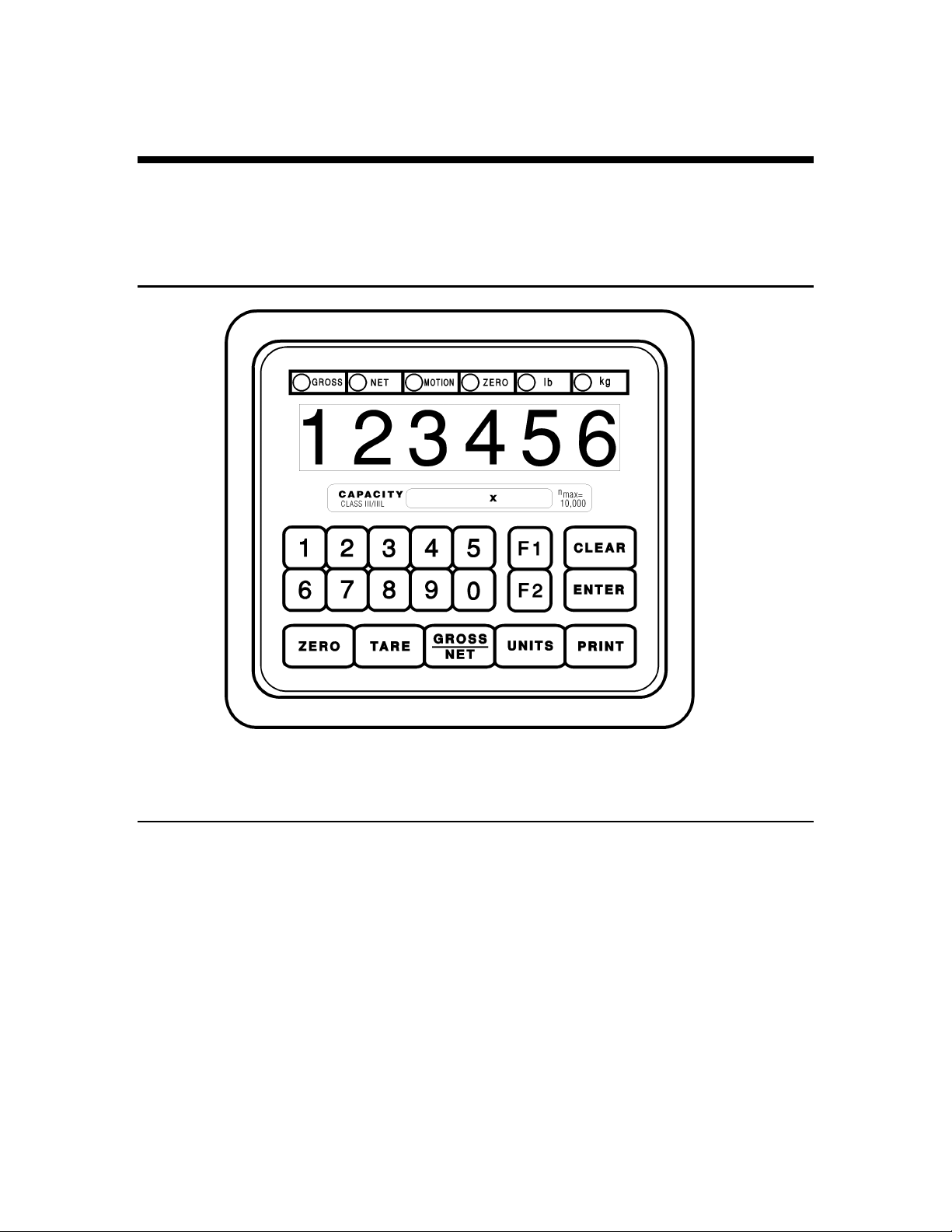
IDS440 Display and Keyboard Diagram

IDS440 Users Manual version 4.2 General Description
5
The IDS440 Display
The IDS440 DISPLAY consists of a 6 character NUMERIC display and 6 statuses LED’s
The NUMERIC display is normally used to display the weight on the scale. The LED’s
display the scale status. When lighted they indicate the following conditions:
GROSS- The number displayed is the gross weight on the scale.
NET - The number displayed is the net weight on the scale.
MOTION- The weight on the scale is changing (not stable).
ZERO- The scale is at "Center of Zero".
lb- The weight displayed is in increments of pounds.
kg- The weight displayed is in increments of kilograms.
The IDS440 Keyboard
The keyboard is used to initiate weighing functions and for data input and setup of the
IDS440. It is divided into 3 sections: Numeric Keypad, Function Keys, and Control keys
as shown on the previous page.
Numeric Keypad
The numeric keypad is used for numeric data entry. Alphanumeric entry is performed
using a three-digit code for every alphanumeric character. Some system parameters may
require alphanumeric entry. Instructions for alphanumeric entry are provided where
needed.
Function Keys
The function keys ZERO, TARE, GROSS/NET, UNITS and PRINT are used to perform
the functions of zeroing the scale, tarring the scale, switching the weight display between
gross and net display, switching the weight display between LB and KG display, and
printing the weight. The function keys F1 and F2 are programmable using Scale Basic
functions.
Control Keys
The control keys ENTER, and CLEAR are used to control the data entry operations for
ID’s, setpoints and setup.

IDS440 Users Manual version 4.2 Installation and Setup
6
Installation and Setup
This section provides information about unpacking, installing, and setup of the IDS440.
It also directs the installer to the appropriate sections of the manual for hardware and
setup installation.
Unpacking the IDS440
Installation begins with unpacking the IDS440. Observe any instructions or cautions,
which appear in the shipping container. Check the items in the shipping container against
the following item check list or the packing list. IDS, Inc. will not accept responsibility
for shortages against the packing list unless notified within 30 days. All equipment and
accessories are inspected and tested by IDS before shipment. Inspect the equipment
carefully. If shipping damage is evident, notify the carrier immediately. Take
photographs if necessary. You are responsible for final claim and negotiations with the
carrier. Save the packing and shipping container in case you need to store, return, or
transport the IDS440 for any reason.
Item check list
• IDS440 - Weight Scale Indicator
• Power cord
• This User's Manual
• Capacity labels
• A sheet that describes the capacity label placement
NOTE: The container may include additional items that have been purchased separately.

IDS440 Users Manual version 4.2 Installation and Setup
7
Installation Guide
Connect IDS440 to load cell
Connect the load cell to the Load Cell Terminal Block located inside IDS440’s enclosure.
See the HARDWARE INSTALLATION AND WIRING section for pin assignments and
a sample cable drawing.
Connect IDS440 to the printer (optional)
The IDS440 can be connected to a printer using Com Port 1 (TB1) for RS232 or Current
Loop interfaces or by using the TTL I/O Port (TB4) for Centronix compatible interfaces.
See Hardware and Wiring Diagrams for pin assignments and sample cable drawings.
See Set Operation Parameters, and Parameter Functions for other communication
setup parameters.
Connect IDS440 to host device (optional)
The Serial Communications Port 2 (TB2) provides a continuous output of scale data.
This is used for connection to a host device such as a computer or to a remote display
(scoreboard). Continuous output transmission can be enabled or disabled and the output
format can be customized to interface with the host device. See Hardware and Wiring
Diagrams for pin assignments and sample cable drawings. See Set Operation
Parameters, and Parameter Functions for other communication setup parameters.
Apply AC Power to the IDS440
After the load cell and optional equipment has been connected, apply power through the
power cord.
Note: The socket outlet should be installed near the equipment and shall be easily
accessible.
On power-up, the IDS440 performs the following tests:
1. A/D Conversion Test - the IDS440 verifies that A/D conversions are taking place.
2. Keyboard Scan - the keyboard is scanned to verify that no keys are engaged.
3. Memory Test - the IDS440 displays "rTEST" while it performs a memory test on
internal memory. If a problem is encountered during the test, an error message is
displayed.
4. Lamp Test - all segments on the numeric display and all LED's are turned on for 5
seconds.
5. Conversion Display - the IDS440 displays "Ad xxx", where "xxx" is the conversion
count. This test takes approximately 10 seconds.

IDS440 Users Manual version 4.2 Installation and Setup
8
6. Stability Check - the IDS440 displays "C xxxx” where "xxxx" is the raw data
difference in scale readings. The IDS440 waits until the data difference is within a
stable range.
To exit the above power on test functions, press the CLEAR key during any test. This is
possible only if the IDS440 has not been locked.
The IDS440 is now ready for initialization, calibration, and configuration. Continue
with Setup Guide.

IDS440 Users Manual version 4.2 Installation and Setup
9
Setup Guide
Setup the IDS440 in the following order:
Initialize to Factory Defaults
The IDS440 is initialized at the factory. It must be re-initialized if the program memory
(EPROM) or the parameter memory (EAROM) is replaced. The Initialize function
clears the memory and sets the configuration parameters to their default values. Use
parameter function 70 described in Parameter Functions to initialize the IDS440.
NOTE: Calibration and setup must be performed after the IDS440 is initialized.
Setup & "Quick" Calibration Guide
The IDS440 should be configured BEFORE calibration. Set Operation Parameters
details all of the scale parameters that are available. To quickly get the IDS440 up and
running, the following Quick Calibration Guide lists only the mandatory parameters that
must be defined. Enter the following scale parameters using the selection outlined in Set
Operation Parameters and Parameter Functions.
Parameter (section) Purpose (Factory Setting)
1 (Set Operation Parameters) Load Cell mv/V (3)
11 (Set Operation Parameters) Decimal Point (none)
12 (Set Operation Parameters) Count-by (1)
17 (Set Operation Parameters) Full Scale Graduations (10,000)
18 (Set Operation Parameters) Overload Graduations (10,200)
60 (Parameter Functions) Calibrate Scale
Calibrate the Weight Indicator
Use Parameter Function 60 to calibrate the weight indicator (page 6-3).
IDS440 Users Manual version 4.2 Built In Application Programs
10
Using the IDS440
The IDS440 has 7 function keys located at the bottom of the keyboard, a numeric keypad,
and 2 control keys (ENTER, and CLEAR). This section of the IDS440 manual describes
what the keys are used for and how to use them.
Keyboard Layout
Operation of Function Keys
The function keys are located on the bottom of the IDS440’s front panel.
Zero
Press the ZERO key to zero the scale. The following conditions must be met for the
ZERO key to function:
• The gross weight is within the configured zero acquisition range: 1% to 100% of full
scale.
• The scale is stable (no motion).

IDS440 Users Manual version 4.2 Built In Application Programs
11
Tare
AUTO TARE:
Press the TARE key. The IDS440 reads the weight on the scale and stores it in the
tare register. The IDS440 switches to NET mode and displays the net weight.
KEYBOARD TARE:
Use the numeric keys to enter a tare weight. Press the TARE key. The IDS440 stores
the entered weight in the tare register and switches to NET display mode.
CLEAR TARE:
Press the numeric ZERO key. Press the TARE key. The tare weight is cleared to
zero and the IDS440 switches to the GROSS mode.
Gross/Net
Press the Gross/Net key to alternate between Gross and Net display modes.
Print
Press the PRINT key to print weight data. Page format 1 is printed if the IDS440 is in
Gross display mode; page format 2 is printed in the Net display mode. See section
Parameter Functions for setup of print formats.
F1 and F2
The F1and F2 keys can be configured to execute any scale basic function (parameters 57
and 58).
When the indicator is in data entry mode, the F1 key can be used for entering a minus
sign; the F2 key can be used to enter a decimal point.
Memory Register Entry
Use the numeric keypad to enter the memory register number (1 to 16). Press the
ENTER key. The IDS440 displays "reg xx" for 1 second and then displays the current
memory register value. Press the CLEAR key if no change is to be made, or enter a new
value and then press the ENTER key. Memory registers are used by the Event Monitor
to calculate setpoint values. NOTE: memory registers are set to zero at power up unless
the battery back up is enabled CFG 41.
Execute a Scale Basic Function
The IDS440 provides up to 16 user programmable functions. User programs 1 thru 16
can be executed by entering 1 to 16 respectively. See the "Scale Basic / Event Monitor"
manual for more information.
Display Time/Date
Enter 19 to display the time, press Enter to display the date, press Enter again to return to
Gross/Net display.

IDS440 Users Manual version 4.2 Built In Application Programs
12

IDS440 Users Manual version 4.2 Built In Application Programs
13
Built In Application Programs
The following built in programs are available:
1. Fill to Setpoint.
2. Checkweigh: Under/Between/Over.
3. Weigh-in / Weigh-out.
4. Axle Weigh – Short Scale.
5. Axle Weigh – Long Scale.
6. ID Tare and Total.
7. Peak Hold.
Use parameter function 73, “Initialize Function Memory”, to activate a built in program.
The initialize function erases function memory and setpoint monitor memory, and
initializes all parameters that have a password level of 1 or 2. Use parameter function 73
before configuring parameters with password level of 1 or 2.

IDS440 Users Manual version 4.2 Built In Application Programs
14
#1 Fill to Setpoint
Press F1 key to enter a setpoint. Place an empty container on the scale. Press F2 key to
begin filling. TTL output 1 turns on until the weight on the scale is equal or greater than
the setpoint.
Installation
Connect TTL output 1 to relay or lamp actuator.
TB4 - Pin 1 TTL output 1
TB4 - Pin 16 Ground (GND)
Setup Parameters:
(See chapter 5: Set Operation Parameters for setup details)
Parameter 43 Minimum scale weight to begin filling. Verifies that a container is on the
scale. Set to 0 if there is no minimum.
Parameter 44 Minimum fill amount. Set to some small value to insure that a fill amount
has been entered.
Parameter 45 Maximum fill amount. Maximum fill weight that will ever be used.
Parameter 46 Scale empty weight. Maximum weight to begin fill. Verifies that an empty
container is on the scale.
Operators Functions
Enter setpoint
Press F1 key to enter the setpoint. Enter the setpoint weight, then press the ENTER key.
Start fill operation
Place the container on the scale (if required). Press F2 key to begin fill operation.
Stop fill operations
Press the Clear key to stop fill operation.
Print Results
Press the Print key to print the Gross, Tare, and Net results of the fill operation.
Error Codes
Error 30 = scale not empty
Error 31 = minimum weight error: container is not on scale
Error 32 = tare weight error: tare function failed, scale not stable (motion)
Error 33 = setpoint less than minimum setpoint amount
Error 34 = setpoint more than maximum setpoint amount

IDS440 Users Manual version 4.2 Built In Application Programs
15
# 2 Checkweigh: Under/Between/Over
The indicator monitors the scale for activity. When the scale goes above the ‘empty’
weight, the indicator waits for stable weight, and then outputs an indication of Under,
Between (OK), or over. The cycle resets when the scale goes below the empty weight.
Installation
Connect TTL outputs to relay or lamp actuators.
Under weight indication TTL 1 TB4 - Pin 1
Between weight indication TTL 2 TB4 - Pin 2
Over weight indication TTL 3 TB4 - Pin 3
Ground GND TB4 - Pin 16
Configure ‘empty’ scale weight. (Parameter 43)
Operators Functions
Enter setpoint weights
Press the F1 key. The display prompts “SP 1. Use the numeric keyboard to enter
setpoint 1, then press the ENTER key. The display prompts “SP 2”. Use the numeric
keyboard to enter setpoint 2, then press the ENTER key. NOTE: use the F2 key to enter
a decimal point if needed.
Recalculate
Press the F2 key to re-check the weight on the scale.
Table of contents
Other Industrial Data Systems Accessories manuals

Popular Accessories manuals by other brands

Atlantic Ultraviolet
Atlantic Ultraviolet Sanidyne PREMIUM user guide

General Monitors
General Monitors S4000T instruction manual

ekwb
ekwb EK-Momentum MSI Z390 MEG ACE installation manual

Davis & Waddell
Davis & Waddell D1517 operating instructions

Hendi
Hendi 820605 Instructions for use

SELT
SELT CASABLANCA installation manual


EUTECH INSTRUMENTS
EUTECH INSTRUMENTS CARBON DIOXIDE GAS instruction manual

LST
LST LAB48 Specification sheet

Tellur
Tellur Compact Pro PD701 user manual

Matchmaster
Matchmaster 34MM-HDS2 instruction manual

Decagon Devices
Decagon Devices Dielectric Leaf Wetness Sensor Owner's/operator's manual

Lufft
Lufft WS800-UBM manual