Industrial Rivet & Fastener Co. RK-9000M User manual
OPERATIONSMANUAL
FORTHEPNEUMATIC‐HYDRAULICRIVETINGTOOL
RK‐9000M

N‐8340000001132
(version2016)
TABLEOFCONTENTS:
1.GENERALSAFETYINSTRUCTIONSANDPRINCIPLES ........................................................3
2.DESCRIPTIONOFTHETOOL......................................................................................................4
2.1.Basicdimensions...............................................................................................................4
2.2.Technicaldata...................................................................................................................4
2.3.Rangeofusage..................................................................................................................5
2.4.Tooloperation...................................................................................................................5
3.TOOLMAINTENANCE...............................................................................................................7
3.1.Dailymaintenance.............................................................................................................7
3.2.Weeklymaintenance.........................................................................................................7
3.3.Generalmaintenance........................................................................................................9
4.SPAREPARTS...........................................................................................................................9
4.1.Ordering............................................................................................................................9
4.2.Listofquicklyexpendableparts.......................................................................................1 0
5.STORAGE...............................................................................................................................10
6.COMPLETETOOLEQUIPMENT...............................................................................................10
7.OPERATIONSANDWARRANTYCONDITIONS.........................................................................10
7.1.Operationconditions.......................................................................................................11
7.2.Warrantycondition.........................................................................................................11

- 3 -
1.GENERALSAFETYINSTRUCTIONSANDPRINCIPLES
ATTENTION!Readallinstructionsandprinciplescarefully.Everypersoninstalling,operatingormaintainingthe
toolmustbefirstthoroughlyacquaintedwiththisoperationsmanualandisobligedtoadheretothefollowing
safetyinstructionsandprinciples:
Thetoolmustnotbeusedforotherpurposesthanthoseforwhichitwasdesigned.
Thetoolmustnotbeusedinadifferentmannerthanthatrecommendedbythemanufacturer
Anyalterationsofthetool,itsaccessoriesorsparepartsremaininsoleresponsibilityofthecustomer.After
agreementthemanufacturerprovidetechnicalsupportindesigningandmakingadditionalalterations.
The tool must be kept in top condition and regularly tested for damage and proper operation. The tool
must be repaired only by an authorized technician or by a person trained by the manufacturer or
supplier.Shouldyouhaveanydemandfortraining,pleasecontactyoursalesagent.
Thetoolmustalwaysbeoperatedinaccordancewithrespectivesanitaryandsafetyregulations.
Allqueriesregardingproperandsafeoperationofthetoolshouldbeaddressedtoyoursalesagent.
Safetyprinciplesthatmustbeadheredtoin connectionwithoperationofthistoolmustbeknowntoall
workerswhooperatethetool.
Whenhandlingthetooltakeextracaretoavoidunwantedactivationandpossibleinjury.
Thetoolmust be during any kind of maintenanceorrepair(doesnotapplytoreplacingnose‐pieces and
emptyingthemandrelcontainer)disconnectedfromthesourceofcompressedair.
Beforeoperatingthetoolalwaystakeupfirmpostureandsteadyposition.
Itisnecessarytopreventbreak‐awayshanksendangeringsafeoperationofthetool.
Neveraimwiththetoolatanotherperson.
Alwayscheckthattheventholesarenotblockedorcoveredandthatthesupplyhoseareingoodcondition.
Workingpressuremustnotexceed95PSI.
Oxygenorotherflammablegassesfrompressurecylindersmustnotserveasadrivingagent.
Whenoperatingthetoolitisrecommendedtousesafetyglassesandutilitygloves.
Ifthecontinuouscycleofrivetingexceeds8hoursperday,itisrecommendedthattheoperatorsuseear
protectors.
When working with the tool the operator must not have loose parts of wear as e.g. a tie, long hair,
jewelleryetc.toavoidgettingcaughtbythetool.
Samesafetyinstructionsapplyforpersonsstandingclosetothetool.
Avoidunnecessarycontactwiththehydraulicfluidtopreventpossibleallergyreactionoftheskin.
Thetoolisnotdesignedforoutdoorandexplosiveenvironment.
Aftertheservicelife,discardthetoolaccordingtotheDisposalActno.185/01Coll.

- 4 -
2. DESCRIPTIONOFTHETOOL
2.1.Basicdimensions
2.2.Technicaldata
weight............................................1,84kg
workingpressure...........................85‐95PSI
strokeforceat0,6MPa.................12,5kN
airconsumption.............................2,0l/stroke
stroke............................................21mm
height............................................275mm
length............................................272mm
width(overtheaircoupling)……....120mm

- 5 -
2.3.Rangeofusage
Thepneumatic‐hydraulictoolisdesignedforrivetingwithblindrivets:
Typeofrivet Al(aluminium) St(steel) Rv(stainlesssteel) Recommendednose‐pieces*
standard Ø4,0 Ø4,0 Ø4,0 nose‐pieceno.4
standard Ø4,8‐Ø5,0 Ø4,8‐Ø5,0 Ø4,8‐Ø5,0 nose‐pieceno.5
standard Ø6,0 Ø6,0 Ø6,0 nose‐pieceno.6
standard Ø6,4 Ø6,4 Ø6,4 nose‐pieceno.6.4
*Recommendednose‐pieceswithrespecttorivetdiameters(doesnotapplyforalltypesofrivets)
2.4.Tooloperation
Fig.1
The manufacturer equipped the tool with a nose‐piece /fig.1 – pos.1/ for a rivet Ø 6.4.Riveting with blind
rivets of different diameters (further on referred to as BR) requiresuse ofappropriatenose‐piecesthatare
locatedintheaccessoriescasingofthetool.
Replacementofnose‐pieces:Connectthetooltothesourceofcompressedair,depressthetriggerandscrew
outthe nose‐piece/fig.1–pos.1/withaspannerno.12.Screwonanewnose‐piece/acc.tothechart/and
tightenit.Nowyoucanreleasethetriggerofthetool.
The tool is equipped with revolving air supply /fig.1 – pos.A75/ which enables manipulation with air supply
beforeaswellasduringtooloperation,airhosedoesnotobstructrivetinginanyposition.
Thetoolisequippedwithmultifunctiontrigger/fig.1‐pos.74/whichenablesfollowing:
1)Rotationalmovementofthetriggeraroundthepin‐riveting.
- Thetriggerisonthefrontextremeposition,notpressed.
- Depressingthetriggershallfixtherivet.

- 6 -
2)Verticalmovementofthetrigger–switchingoffthesuction.
- Pressandlockthetrigger(afterpressingshiftitupcca1,5mm),thenreleasethetrigger,thesuctionis
switchedoff.
- Unlockthetrigger(shiftingthetriggerdowntothestop)andreleaseit.Thesuctionisswitchedonand
thetriggerisinpositionseefig.1.
The tool is equipped with a multifunctional mandrel container /fig.1 – pos.32/ which has the following
positions:
Position0–mandrelcontainerremoved
Position1–mandrelcontainermounted,suctionisswitchedoff
Position2–mandrelcontainermounted,suctionisswitchedon
1)Mountingthemandrelcontainer:
Putandpush themandrelcontainer/fig.1 ‐pos.5/intotheringrelief/fig.1–pos.6/end‐to‐end,thusyou
depressthearrestmentelement,andturntoposition1or2.Themandrelcontainershallthusbeinplace.The
suctionshallinitiateinposition2.Relativepositionofthemandrelcontainerwithairoutlets/fig.1‐pos.7/and
theringrelief/fig.1–pos.7/ensuresthattheoutletairpressuregoesoutinasuitabledirection(e.g.Offward
theoperatorofthetool).
2)Removingthemandrelcontainer:
Turnthemandrelcontainer/fig.1‐pos.32/end‐to‐endtoposition0andpullitoutoftheringrelief/fig.1–
pos.26/.Thesuctionshallthusswitchoff.

- 7 -
Thetoolcanbeoperatedinthefollowingmanners:
1)withthemandrelcontainerremovedinposition0:
Suctionswitchesoffbyturningandremovingthemandrelcontainer/fig.1‐pos.32/.InsertBRintotheriveting
toolthroughthenose‐piecehole.DepressthetriggertomovethejawsoffwardtheBRhead.Themovement
endswhenreachingmax.stroke,correctBRwithrespectformaterialgaugeshalltearofftheshank(riveting)
foronestrokeof thetool.Releasingthetriggershallreturnthejawstoinitialpositionandreleasedtorn‐off
shankcanberemovedfromthenose‐piecebytiltingthetool./fig.1‐pos.1/.
2)withthemandrelcontainermountedinposition1:
Mountingandturningthe mandrelcontainer/fig.1‐pos.32/toposition1shallarrestit.InsertBRintothe
riveting tool through the nose‐piece hole. Depress the trigger to move the jaws offward the BR head. The
movementendswhenreachingmax.stroke,correctBRwithrespectformaterialgaugeshalltearofftheshank
(riveting)foronestrokeofthetool.Releasingthetriggershall return the jaws to initial position and the
releasedtorn‐offshankcanbetransportedintothemandrelcontainerbytiltingthetool.
3)withthemandrelcontainermountedinposition2:
Suctionswitchesonbyturningthemandrelcontainer/fig.1‐pos.32/toposition2.Inthispositionthesuction
holdsBRinthenose‐piece/fig.1‐pos.1/whichenablesrivetinginanypositionwithoutdangerofBRfallingout
ofthenose‐pieceofthetool.Depressingthetriggershallperformriveting.Releasingthetriggershalltransport
theshankintothemandrelcontainer.Ifthemandrelcontainerisfullwithshanktoappx.70%,itisnecessaryto
removeandemptyitinaspecifiedmanner(e.g.toapreparedcontainer).Overfillofthemandrelcontainer
mayresultinfailureoftherivetingtool.
3.TOOLMAINTENANCE
Duringmaintenancethetoolmustbedisconnectedfromthesourceofcompressedair!!!
3.1.Dailymaintenance
Before starting work, apply severaldropsoflubricatingoil(werecommendhydraulicoilHYSPINAWHM32
CASTROL) into the air inlet of the tool, on condition there is no lubricating device connected in the air
distribution.
Checkthetoolforairleakage,ifnecessaryreplacedamagedhosesandclasps.
Ifthepressureregulatorisnotequippedwithafilter,blowthroughtheairhosebeforeitsconnectiontothe
toolinordertogetridofimpuritiesandwater.Ifthepressureregulatorhasafilter,dryitout.
Checkwhetherthefixednose‐piececorrespondstotheBRdiameterandthatallscrewthreadsandjointsare
tightenedproperly.
Checkwhethertheholesforpassagearereallyempty.Ifitisnotso,itisnecessarytoremovethedamaged
part,cleantheholeorreplacethedamagedpartwithanewone,seeparagraph3.2weeklymaintenance.
3.2.Weeklymaintenance
Cleaningofthetoolandreplacementofwornornon‐functionalparts.

- 8 -
Fig.2
Disassembly:
Disconnectthetoolfromthesourceofcompressedair,unscrewthefrontnozzle/fig.2‐pos.9/bymeansofa
spannerno.23,setthespannerno.17(15)ontotheclampingsleeve/fig.2‐pos.3/,setthespannerno.17onthe
backnut/fig.2‐pos.6/andloosen.Unscrewtheclampingsleeve,replacethejaws/fig.2‐pos.2/andconduit‐
suction complet /fig.2 ‐ pos.8/. All used threads are clockwise. Clean the dismounted parts thoroughly and
checkthemvisually,especiallythefollowing:
1)Jaws/fig.2–pos.2/‐ifwornordamaged,replaceit,ifdirty,cleanitwithawirebrush.
2)Nose‐piece/fig.2–pos.1/‐forwearoffunctionalsurfacesofthetaper.
3)Conduit‐suctioncomplet/fig.2‐pos.8/‐inspectpartsoftheassembly,jawpusher/fig.2‐pos.804/,spring
/fig.2‐pos.803/,washerofspring/fig.2‐pos.805/,O‐ring/fig.2‐pos.802/andconduit‐suction/fig.2‐
pos.801/‐ifdamagedorworn,replaceitwithanewone.
4)Frontnozzle/fig.2‐pos.9/‐checkfordamageoftheinternalsurface(Ø20).
5)Scraperring/fig.2‐pos.5/‐ifdamagedorworn,replaceitwithanewone.
6)Mandrelcontainer‐ifthemandrelcontaineroritsbottomarewornordamaged,replacethemwithnew
ones,otherwisethereisdangerofthetorn‐offshankpoppingout.
Assembly:
Mount the parts (see par. disassembly) in a reverse order. On theoutersurfaceofthejaws/fig.2–pos.2/
applyadropoflubricatingoil(werecommendhydraulicoilHYSPINAWHM32CASTROL),applythinlayerof
plastic lubricant MOGUL LV 2‐3 to the conduit‐suction complet /fig.2 – pos.8/. Basic set‐up of the jaws is
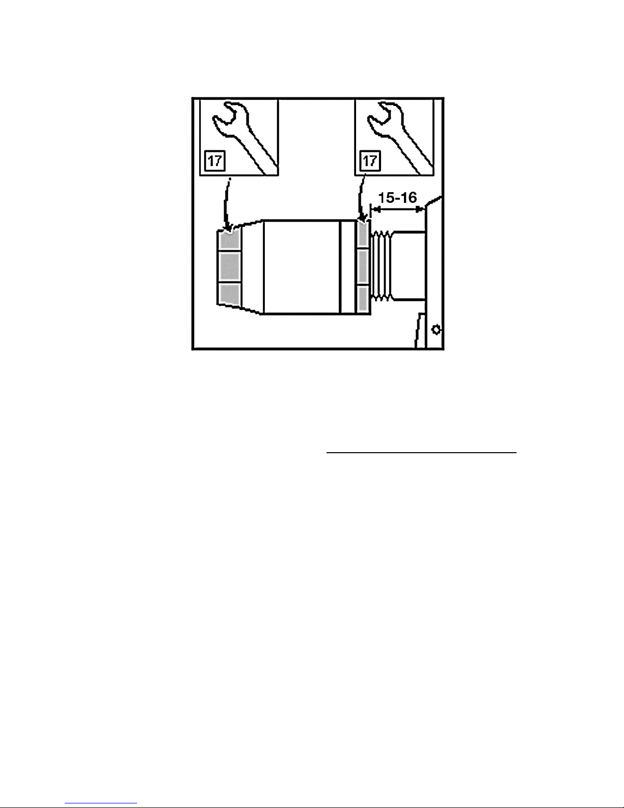
performedasinfig.3.
- 9 -
Fig.3
3.3.Generalmaintenance
General maintenance shouldbeperformed after about 500000strokes oronce every threeyears. The tool
mustbecompletellydisassembledandallsealsandwornpartsmustbereplaced.Thisrepairmaybecarried
outbyanauthorizedtechnicianonlyorapersontrainedbythemanufacturerorsupplier.
4.SPAREPARTS
4.1.Ordering
Orderthesparepartsexclusivelyfromthemanufacturerorfromyoursalesagent.
Theordermustcontain:
a) toolserialnumber
b) numberoforderedpart
c) numberofpieces
d) nameofyourcompanyandpreciseaddress
e) yourtaxidentificationnumberandidentificationnumber

- 10 -
4.2.Listofquicklyexpendableparts
Nose‐piece4.........................................................… RK9000‐BP1‐3
Nose‐piece5.........................................................… RK9000‐BP1‐4
Nose‐piece6.........................................................… RK9000‐BP1‐5
Nose‐piece6,4..………………………………………………..… RK9000‐BP1‐6
Clampingsleeve......................................................RK9000‐BP3
Setofjaws................................................................ RK9000‐BP2
Conduitsuction…...........................................……….. RK9000M‐BP7
"O"ring7,1/1,6........................................................RK9000‐BP8
Springofjawpusher………………………………………….….RK9000‐BP9
Jawpusher.…………………………………………..……..…….RK9000MLS‐BP10
Scraperring..………………………………………….…….……... RK9000‐BP4
NutHP..………………………………………….…………….……. RK9000‐BP5
Mandrelcontainer…………………………………………..…… RK9000M‐BP42
5.STORAGE
Thepneumatic‐hydraulictoolembeddedinashippingcontainermustbestoredinenvironmentwithrelative
humidityto70%andtemperaturerangingfrom+5oCto+40oC,withoutaggressiveevaporationofsalts,acids
andcaustics.
6.COMPLETETOOLEQUIPMENT
Replaceablenose‐pieceslocatedinaplasticplate,Operationsmanual,Certificateofwarranty.
7.OPERATIONSANDWARRANTYCONDITIONS
For
reliable function
of
the tool we recommend to use treated
compressed
air.
Treated
compressed air means compressed atmospheric air bare
of
solid
particles
and
water,reduced
to required pressure and lubricated with anti-corrosive
oil.

- 11 -
7.1.Operationconditions
Forreliablefunctionofthetoolitisnecessarytousetreatedcompressedair.Treatedcompressedairmeans
compressed atmospheric air bare of solid particles and water, reduced to required pressure and lubricated
withanti‐corrosiveoil.Immediatelybeforethetooltheremustbearegulationvalvesettomaximumoutlet
pressureof0,7MPa,airfilterandlubricationinthecircuitofcompressedair.
Sound‐pressurelevelofimpulsenoise,LpAI=107,7dB(A),peakC‐weightedsoundpressure,CLCpeak=114,1
dB(C), against which during continuous and long‐term operation it is recommended to use ear protectors.
AverageoverallvibrationtotalvalueLavw,T=126,8dBre10‐6m.s‐2,averageoverallvibrationtotaleffective
valueavw,T=2,188m.s‐2.
Thetriggerenablessafecontrolofthetoolwithaforcemax.10N<50Nwithoutreleasingthegrip‐handle
accordingtothehealthregulation.
7.2.Warrantyconditions
Forreliableandsafefunctionofthetoolitisnecessarytoadheretoinstructionsandprinciplesstatedabove.
Forthe warrantyperiodthecustomermustnotperformanyalterationsotherthanthosepermittedbythe
manufacturer, see paragraph 2. 1, 3. 1, 3. 2. Other non‐detachable parts are secured with paint. In case of
neglecting this protection the manufacturer shall not admit possible warranty repairs. To admit warranty
repair the customer must submit confirmed warranty certificate ofthetool,Certificateofqualityand
completenessorproofofpurchase.Thewarrantyperiodis24monthsfromthedayofpurchaseconfirmedin
theWarrantycertificateifthepurchasecontractdoesnotstateotherwise.
Warrantyisvalidprovidedthatthefollowing:
Generalsafetyinstructionandprinciples(paragraph1)
Tooloperation(paragraph2.4)
Dailyandweeklymaintenance(paragraph3.1and3.2)
Storage(paragraph5)
Operationsandwarantyconditions(paragraph7)
Warrantydoesnotapplytoquicklyexpendableparts(seeparagraph4.2.
Table of contents
Other Industrial Rivet & Fastener Co. Rivet Tools manuals


