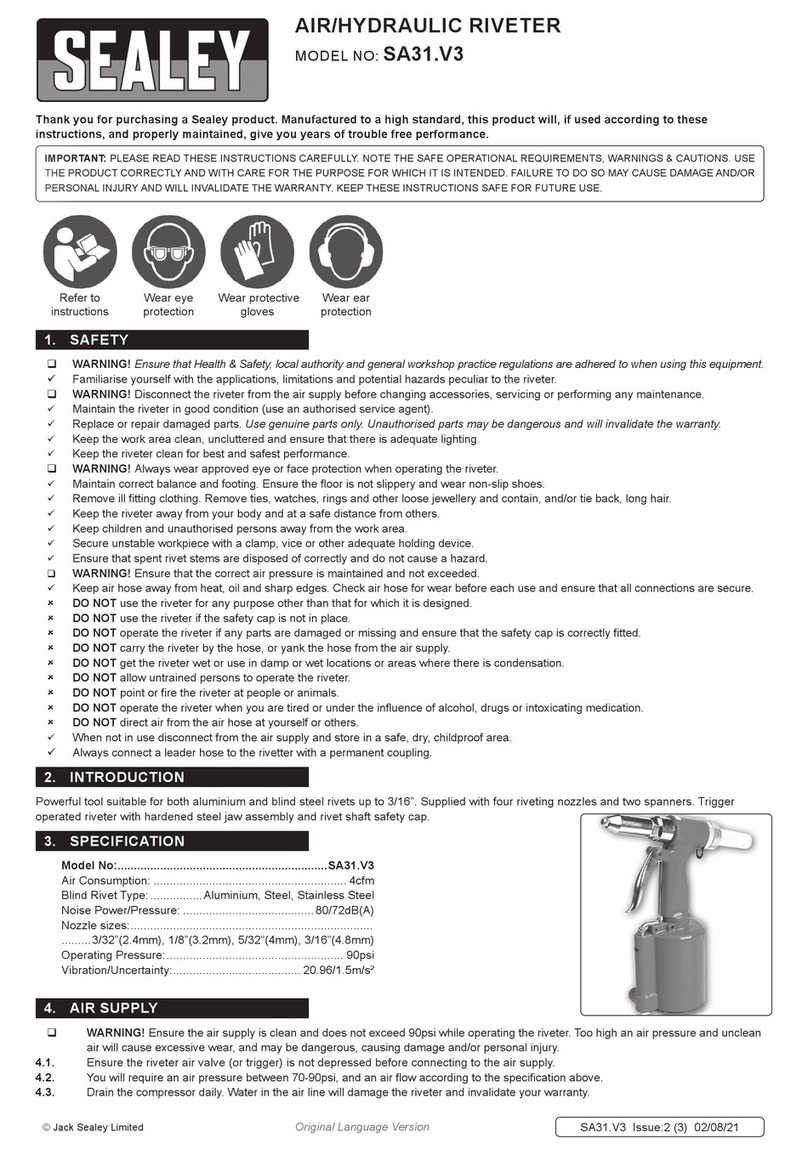
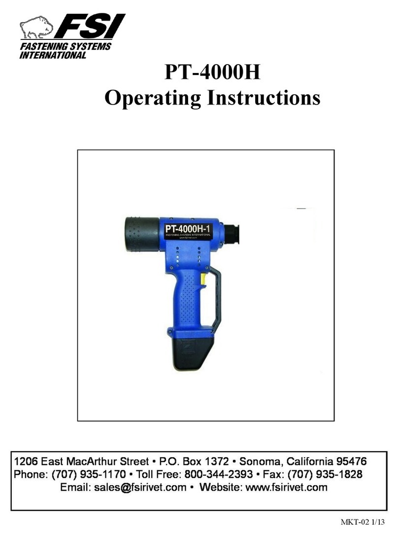
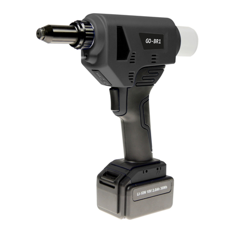
Rivtec RT-W12 User manual

RT-W12
Air Rivet Nut Tool
M5 - M12
OPERATOR’S MANUAL
IMPORTANT
Read this Operator’s Manual
carefully before operation.
Keep this manual for future
reference.
Rivtec Ltd
4 Hotunui Drive, Mt Wellington, Auckland New Zealand
Ph: 09 276 7021 I Fax: 09 276 7021
Email: [email protected]
Web: www.rivtec.co.nz
Rivtec® Ltd 03/15
TROUBLE SHOOTING
Tool installs rivet-nut
but will not reverse.
Usually because the tool is low
on oil and the pull piston is not
stroking far enough to engage the
reversing valve.
Inject Hyraulic Oil into the tool
using the priming syringe.
Indication Cause Solution
Tool installs rivet-nut
but strips thread on
Mandrel or inside the
rivet-nut.
The air pressure setting is too
high.
Adjust with the red knob lo-
cated on the base of the tool
Tool installs rivet-nut’s
erratically.
Usually because the air supply to
the tool is varying in pressure.
The tool functions pull-to-
pressure (air) Ensure a reliable
air supply.
The air motor runs
continuously after
installing rivet-nut.
The pressure on the reversing
valve is too heavy.
Adjust the reversing-spring ten-
sion located inside the reverse
button.
Tool remains engaged
with rivet-nut after
installation.
The air motor reverse period
needs to be extended.
Use a hex key in the bleed
valve. Adjust in 1/4 turn incre-
ments.
Insert will not engage
with the mandrel.
Usually a worn or damaged thread
on the Mandrel.
Replace with new Mandrel or
dress the thread.
Air escapes from the
relief valve.
The air supply pressure is too
high.
Reduce accordingly, MAXI-
MUM pressure is 7-bar (100psi)
The air motor runs
slowly.
Most times, the air motor needs
lubrication.
Drips a small quantity of Motor
Lubricating Oil in to the airline.

INTRODUCTION
The W12 is a cost-effective and reliable air rivet nut tool. It is suitable for both production and
project based installations due to the quick change mandrel system and the adjustable air pres-
sure stroke feature.
SPECIFICATIONS
Weight .............................................. 2.45kg
Length ............................................. 305mm
Height .............................................. 292mm
Width ............................................... 124mm
Stroke (Max)........................................ 9mm
Air Pressure .................................... 5-7 bar
PACKAGE ACCESSORIES
■W12 Rivet Nut Tool
■1 x Nose assembly for M5 Rivet Nuts
■1 x Nose assembly for M6 Rivet Nuts
■1 x Nose assembly for M8 Rivet Nuts
■1 x Nose assembly for M10 Rivet Nuts
■1 x Nose assembly for M12 Rivet Nuts
■Padded plastic carry case
■Lubricating Oil Bottle
■Hydraulic Oil Bottle
■5ml Syringe
■3mm and 4mm Hex Key
■Operating Manual
Air Supply
1
SAFETY INSTRUCTIONS
Caution! To ensure proper functioning and safe operation, read this Operator’s
Manual carefully before operating the RIVTEC® RT-W12 tool
■The W12 should be used exclusively to set rivet-nuts and rivet-studs.
■DO NOT overload the tool – work within the prescribed work capacity
■ALWAYS wear eye protection when working with the tool. Personal protection such as
clothes, gloves, safety helmet, non-slipping shoes, ear protectors and protection against
fall are highly recommended.
■This tool is NOT designed for use in explosive atmospheres.
■DO NOT use the tool as a hammer.
■Ensure the tool is not damaged before connecting to the air supply.
■Repair work must be carried out by trained personnel. In case of doubt, ALWAYS send
back the tool to the supplier.
■ALWAYS disconnect the air supply when adjusting, servicing or removing any part of the
tool.
■Keep ngers off the trigger when connecting the air supply or if the air supply fails.
■Keep ngers away from the front of the tool when connecting the air supply or setting
rivets.
■DO NOT point the tool at anyone.
■DO NOT operate tool with the nose housing removed.
■DO NOT modify the tool in any way. Modications could damage the tool.
■The operating pressure must not exceed 7 bar.
■Wash hands if exposed to hydraulic uid or lubricant.
■Keep hair, ngers and loose clothing away from moving parts of the tool.
6
This tool is designed to operate on clean, dry, regulated compressed air between 75 and
100psi. It is preferable to include an air lter, pressure regulator and automatic oiler within 4.5
metres of the tool if possible. An air lter is recommended to remove contaminates and mois-
ture that are contained in compressed air, ltering will signigantly prolong the life of the tool.

NOSE REPLACEMENT PROCESS
1. Disconnect the tool from the compressed air supply
2. Undo the Locking Ring from the Anvil.
3. Remove the Anvil with the Locking Ring from the nose assembly holder (the Locking
Ring remains on the Anvil)
4. Unlock and move the Front Sleeve forward.
5. Retract the spring loaded Security Part (7) towards the rear of the tool to release the
Mandrel.
6. In this position, release the Mandrel by turning it counter-clockwise.
7. In this position, screw the selected Mandrel until it stops by turning clockwise.
8. Release the Security Part (7) and ensure the retaining device covers the hexagon of the
Mandrel.
9. Push the Front Sleeve backwards and secure.
10. Screw the relevant Anvil with Locking Ring into the nose assembly holder.
11. Adjust the Anvil to the relevant material thickness then secure Locking Ring.
MAINTENANCE
Description of the pressue regulation
system
The following can be found at the bottom of
your W12 Tool:
Caution! Disconnect the air supply while relling the hydraulic oil. Keep the tool
upright during all operations.
Mandrel
Anvil
Front Sleeve
Caution! Disconnect the air supply while servicing front end to avoid injury.
Trigger
5 2
Locking Ring
Lubrication
It is important that the tool be properly lubricated. There may be insufcient oil if the stroke of
the tool is too small for proper installation of nuts/bolts. Without proper lubrication the tool will
not work properly and parts will wear prematurely. First check whether the stroke setting is
correct. Check the oil level indicator to see whether loss of oil has occurred. The tool has lost
oil if the oil level indicator pin no longer protrudes.
Adding Oil to your W12
1. Keep the tool upright during all operations. Disconnect the tool from the air supply.
2. Unscrew the cap screw from the body using the allen wrench included. Check whether
the O-ring remains in the hole.
3. Fill the syringe (included) with hydraulic oil.
4. Screw the lled syringe up to the O-ring in the hole. Then slowly inject the oil into the
tool (Make sure no air is injected) Adequate oil has been added as soon as resistance
is sensed. The excess oil will ow back when the syringe is release if more oil is added
than necessary.
5. Unscrew and remove the syringe from the body. Check whether the O-ring remains in
the hole.
6. Screw the cap screw into the hole using the allen wrench.
7. Wipe off any excess oil.
Set screw for pressure adjustment
Pressure Indicator
Needle valve for time of return
Oil level indicator

DIAGRAM
3
PARTS LIST
NO. DESCRIPTION CODE
1M5 Mandrel NHRS-W12-M5
1M6 Mandrel NHRS-W12-M6
1M8 Mandrel NHRS-W12-M8
1M10 Mandrel NHRS-W12-M10
1M12 Mandrel NHRS-W12-M12
2M5 Anvil NHRS-W12-2-M5
2M6 Anvil NHRS-W12-2-M6
2M8 Anvil NHRS-W12-2-M8
2M10 Anvil NHRS-W12-2-M10
2M12 Anvil NHRS-W12-2-M12
3Locking Ring NHRS-W12-3
4 - 6 Front Sleeve Complete NHRS-W12-040506
7-11 Mandrel Holder Assembly NHRS-W12-78911
10 Priming Syringe NHRS-W12-10
14 Hydraulic Piston/Air motor NHRS-W12-14
14-02 Thrust Washer (TK) NHRS-W12-14-02
14-04 Bearing (front) Gear Box NHRS-W12-14-04
14-09 Bearing (rear) Air Motor NHRS-W12-14-09
14-11 Vanes set for Air Motor NHRS-W12-14-11
14-15 Bearing (Rear) Air Motor NHRS-W12-14-15
14-16 Pin (short) Motor Valve NHRS-W12-14-16
14-17 Push Rod NHRS-W12-14-17
14-19 Push Rod (CW) Reversing NHRS-W12-14-19
14-24 Ball (plastic) for Valve NHRS-W12-14-24
14-25 O-ring (30x1) NHRS-W12-14-25
14-27 Push Rod (CCW) reversing NHRS-W12-14-27
14-28 COVER Plate reversing valve NHRS-W12-14-28
14-29 Csk Socket Screw NHRS-W12-14-29
14-30 O-ring NHRS-W12-14-30
14-31 Hardened Washer NHRS-W12-14-31
15 Bearing (rear) for Air Motor NHRS-W12-15
16 Rod-Seal Lipped SA 18x26x6.5 NHRS-W12-M-16
18 Blled Screw (M5x9) NHRS-W12-M18
21 Hydraulic Body NHRS-W12-21
26 Aluminium Connector Sleeve NHRS-W12-26
27 Plastic Sleeve for Air Motor NHRS-W12-27
28 Retaining Pin for Connector NHRS-W12-28
NO. DESCRIPTION CODE
29 Return Spring NHRS-W12-29
30 Spring for Reverse Button NHRS-W12-30
31 Rear Cap (and return spring) NHRS-W12-31
32 Washer for Hydraulic Piston NHRS-W12-32
34 Reversing Button NHRS-W12-34
38 Air Piston Assembly NHRS-W12-38
42 Air Piston O-Ring (89x4) NHRS-W12-42
48 Pressure Relief Valve (inlet) NHRS-W12-48
49 Pressure Regulation Valve NHRS-W12-49
52 Regulator Screw NHRS-W12-52
57 Connecting-Rod for Air Cylinder NHRS-W12-57
64 O-Ring (4x2) for Valve Tube NHRS-W12-64
66 O-Ring (10x2) for Air Piston NHRS-W12-66
68-70 Trigger Button Components NHRS-W12-686970
71 O-Ring (4x1) for Valve Tube NHRS-W12-71
72 Needle Valve for time Return NHRS-W12-72
74 O-Ring (4x2.2) for Valve Tube NHRS-W12-74
77 Spiral Return-Spring for Valve NHRS-W12-77
79 Pusher for Reversing Spring NHRS-W12-79
DS Drive Shaft for Air Motor NHRS-W12-DS
VANES Vanes for Air Motor NHRS-W2-VANES
POA 3/16” UNC Mandrel NHRS-W12-3/16
POA 1/4” UNC Mandrel NHRS-W12-1/4
POA 5/16” UNC Mandrel NHRS-W12-5/16
POA 3/8” UNC Mandrel NHRS-W12-3/8
4


