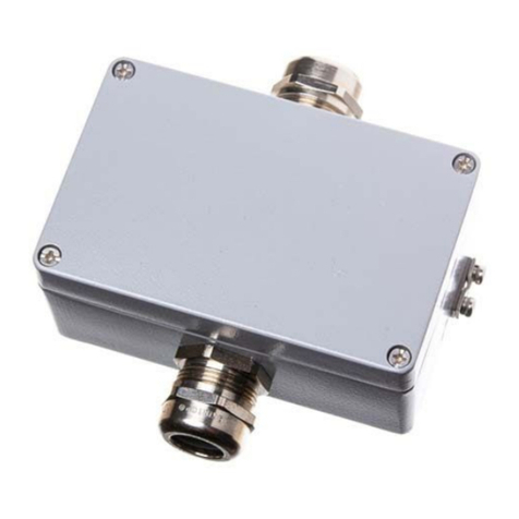
Industrial Scientific OLDHAM 300 Series Operating instructions

300 SERIES
L
LE
EL
L
D
DE
ET
TE
EC
CT
TO
OR
R
D
DE
ET
TE
EC
CT
TO
OR
R-
-T
TR
RA
AN
NS
SM
MI
IT
TT
TE
ER
R
F
FO
OR
R
C
CO
OM
MB
BU
US
ST
TI
IB
BL
LE
E,
,
T
TO
OX
XI
IC
C
G
GA
AS
SE
ES
S
A
AN
ND
D
O
OX
XY
YG
GE
EN
N
O
OP
PE
ER
RA
AT
TI
IO
ON
N
A
AN
ND
D
M
MA
AI
IN
NT
TE
EN
NA
AN
NC
CE
E
M
MA
AN
NU
UA
AL
L
Ref.: NP300 GB
Revision G

3
GAS DETECTION
Thank you for purchasing an INDUSTRIAL SCIENTIFIC instrument. We appreciate your business.
We trust that our commitment to the technical excellence of our products will ensure your complete
satisfaction.
Please read the following document carefully.
L
LI
IM
MI
IT
TA
AT
TI
IO
ON
N
O
OF
F
L
LI
IA
AB
BI
IL
LI
IT
TY
Y
* INDUSTRIAL SCIENTIFIC will not be liable under any circumstances for material losses, personal injury or
death resulting in whole or in part from the inappropriate use of this equipment, the installation or storage of this
equipment not in conformance with the instructions and warnings presented in this manual and/or not in
conformance with current standards and regulations.
* INDUSTRIAL SCIENTIFIC neither allows nor authorizes any other company, individual or legal entity to make
any claims as to the liability of INDUSTRIAL SCIENTIFIC, even if said company, individual or legal entity is
directly involved in the sale of INDUSTRIAL SCIENTIFIC products.
* In no event will INDUSTRIAL SCIENTIFIC be liable for any direct or indirect damage including those resulting
from the sale and the use of its products IF THOSE PRODUCTS WERE NOT SPECIFIED AND SELECTED
BY INDUSTRIAL SCIENTIFIC FOR SUCH USE.
O
OW
WN
NE
ER
RS
SH
HI
IP
P
C
CL
LA
AU
US
SE
ES
S
* The images, blueprints, specifications and information contained in this document belong to INDUSTRIAL
SCIENTIFIC.
* This information may not be physically, electronically or otherwise reproduced, copied, disclosed or translated,
either in part or in whole, or used in the manufacturing or sale of INDUSTRIAL SCIENTIFIC equipment, nor for
any other reason without prior permission from INDUSTRIAL SCIENTIFIC.
W
WA
AR
RN
NI
IN
NG
GS
S
* This document is not contractual. On behalf of its clients, INDUSTRIAL SCIENTIFIC reserves the right to
modify the technical characteristics of its equipment without notice to improve product performance.
* CAREFULLY READ THIS DOCUMENT BEFORE USING THE PRODUCT: this document should be
carefully read by any individual who has or who will have the authority to use, maintain or repair this equipment.
* Any and all warrantees and performance claims will only be valid if the equipment is operated, maintained
and repaired in accordance with INDUSTRIAL SCIENTIFIC directives, by INDUSTRIAL SCIENTIFIC
personnel or by personnel appointed by INDUSTRIAL SCIENTIFIC.
W
WA
AR
RR
RA
AN
NT
TY
Y
*Two-year return to factory warranty under normal operating conditions on parts and labor, consumable materials
excluded (sensors, filters, etc.)

4
CONTENTS
I. INTRODUCTION ...................................................................................................................... 5
1. General Information ...............................................................................................................................5
2. Composition.............................................................................................................................................5
II. INSTALLATION AND CONNECTIONS ................................................................................... 5
1. INSTALLING THE DETECTORS.........................................................................................................5
1.1 Layout...............................................................................................................................................5
1.2 Mechanical installation....................................................................................................................6
2. ELECTRICAL CONNECTIONS............................................................................................................7
2.1. Wiring specifications........................................................................................................................7
2.2. Cable glands and cable types...........................................................................................................7
2.3. Connections for the various types of sensors ...................................................................................7
2.4. Operating mode..............................................................................................................................10
III. POWERING UP AND USE..................................................................................................... 11
1 Powering up...........................................................................................................................................11
2. 4-20 mA analog output..........................................................................................................................12
IV. MAINTENANCE .................................................................................................................... 12
1. Calibration.............................................................................................................................................13
1.1. Recommendations...........................................................................................................................13
1.2. CEX 300 calibration.......................................................................................................................14
1.3. CTX 300 calibration.......................................................................................................................15
1.4. COX 300 Calibration, “OXYGEN” type........................................................................................17
1.5. CSC 300 (semiconductor) calibration............................................................................................18
1.6. CTX300 CO2calibration ................................................................................................................19
1.7. CTX300 CO2 Linearization card ...................................................................................................20
2. Replacing a sensor .................................................................................................................................26
3. Disposal .................................................................................................................................................26
4. Replacement Parts List ..........................................................................................................................26
4.1. CEX 300-type Combustible Sensor ................................................................................................26
4.2 CTX/COX 300 Toxic or Oxygen Sensor .........................................................................................28
4.3 CSC300 Semiconductor Sensor......................................................................................................30
4.4 CTX300 CO2 Sensor ......................................................................................................................30
V. PARTICULAR SPECIFICATIONS FOR USE IN EXPLOSIVE ATMOSPHERES IN
ACCORDANCE WITH THE EUROPEAN ATEX 94/9/CE DIRECTIVE. ........................................ 31
1. SPECIFICATIONS FOR MECHANICAL AND ELECTRICAL INSTALLATIONS IN
EXPLOSIVE ZONES. ................................................................................................................... 31
2. PERFORMANCE SPECIFICATIONS FOR THE CEX 300 EXPLOSIVE GAS DETECTOR ... 31
2.1. Technical Specifications and Particular Instructions for the CEX300 Explosive Gas Detector ...32
3MARKINGS: .......................................................................................................................... 34
VI CERTIFICATIONS ................................................................................................................. 35
ANNEX 1 ...................................................................................................................................... 39
ANNEX 2 ......................................................................................................................................
41
ANNEX 3 ...................................................................................................................................... 42

5
I. INTRODUCTION
1. General Information
300 Series gas detectors are designed to measure combustible toxic gases or vapors and oxygen.
With robust materials, a specifically-adapted design, appropriate accessories, INOX bolts, and a
polyamide case (IP66) (IP55 for the CO2version), 300 series detectors are designed to withstand the
roughest conditions.
.
2. Composition
Sensor type CEX 300
CTX 300
Toxic
Oxygen
Semiconductor
CO2
Gases detected
Combustible gas
Common toxic
gases detected
Oxygen
- Combustible gas
- Solvents
- Some Freons
CO
2
Detection method
Catalytic oxidation
Electrochemical
sensors
1
Electrochemical
sensor
Semiconductor sensor
Infrared
absorption
Type of sensor
pack
Explosion-proof
sensor
Pre-calibrated
removable
sensor pack2
Pre-calibrated
removable sensor
pack: 0-30% scale
or 0-100%
volume.
Removable sensor pack,
not pre-calibrated
Removable
sensor pack
Infrared
column, not
pre-calibrated
Options
Cable gland for
flexible cable or
armored cable3
With display
With display
Certification
ATEX II 2GD4
None
None
None
None
II. INSTALLATION AND CONNECTIONS
For use in explosive atmospheres: in accordance with the European directive ATEX 94/9/EC, you
must read the “Particular Specifications” paragraph.
1. INSTALLING THE DETECTORS
1.1 Layout
While the measuring sensor is always located on the underside of the detector, several factors
determine where the detector should be located:
•If the gas being measured is lighter than the air, place the detector near the ceiling.
•If the gas is heavier than the air (CO2and Freons, for example) place the detector close to the
floor.
•Near offtake points.
•Generally, in locations where gas may accumulate, taking into consideration both
- the effects of temperature, and
- the direction of winds.
1Specific to each gas
2Choice between several scales
3Requires grounding
4EEx ed IIC T6 (-20 to 60°C)

6
Factors to consider when determining the best placement for the detector:
⇒Potential sources for vapor and gas emissions
⇒Characteristics of gases and vapors (density)
⇒Air circulation
-inside: mechanical or natural ventilation
-outside: wind direction and velocity
⇒Effects of temperature
⇒Local constraints (air flow, water)
Detectors should always be located in an easily accessible location for maintenance purposes.
Special accessories may be necessary to protect the equipment against any liquid projectiles, dust,
direct sunlight or low temperatures in the area.
1.2 Mechanical installation
Method 1: wall-mounted
Drilling diagram
Method 2: ceiling-mounted
Same drilling diagram, support brace used
1
3
2

7
REF.
No.
DESCRIPTION
OFSA REF
MATERIAL
1
1
CEX / CTX300 BRACE
6132380
INOX
2
4
CHC LI2 SCREW
6902218
INOX
3
4
A25 ACCD WASHER
6905518
.
2. ELECTRICAL CONNECTIONS
2.1. Wiring specifications
If needed: consult the grounding instructions for INDUSTRIAL SCIENTIFIC instruments and
related connection materials in Annex 1.
2.2. Cable glands and cable types
Sensor types Cable gland type Cable entry
CTX 300 (TOX and OX)
CTX 300 SC
CTX 300 CO2
Nickel-plated brass
Neoprene
Between 6–11 mm
CEX 300 with shielded cable
Nickel-plated brass
Between 6–11 mm
CEX 300 with armored cable5
Double compression nickel-
plated brass
Between 8.5–16 mm
2.3. Connections for the various types of sensors
CEX 300 CTX 300 (TOX
and OX)
CTX 300 (TOX
and OX)
without display
CTX 300
SC and
CO2
without
display
Output
signal voltage 4-20 mA 4-20 mA 4-20 mA
Number of
wires 3 wires 3 wires 2 wires 3 wires
Max.
impedance
(Z) of the line
Refer to the characteristics for the central controller
The CEX 300 sensor only connects to INDUSTRIAL SCIENTIFIC
central controllers
5Here, the CEX 300 case is equipped with a grounding reclaim screw to connect the cable armor to the ground cable.

8
a) Connection of a 3-wire sensor to an INDUSTRIAL SCIENTIFIC central controller
- 1 wire (+) continuous power supply →No. 3
- 1 wire (-) continuous power supply (0 volt mass) →No. 2
-1 output signal wire →No. 1
b) Connection of a 2-wire sensor to an INDUSTRIAL SCIENTIFIC central controller
-1 wire (+) →No. 3
-1 signal wire →No. 1
c) Connection of a 3-wire CTX300 sensor to a non-INDUSTRIAL SCIENTIFIC controller and
to an internal power supply.
(R) Maximum resistance = 200 Ω.
(1) 15 ≤ VCC ≤ 32
18 ≤ VCC ≤ 30 for CO2
Max I: 130 mA
1
2
3
Control Unit
Detector
+ 24 Vcc
GND
Signal
3
2
1
Control Unit
Detector
+ 24 Vcc
Signal
3
2
1
3
2
1
-
Power
Detector
Control
Unit«
other »
3
2
1
+ 24 Vcc
GND
Signal
+
R
(1)
Formant la boucle de courant 4/20 mA sur 2 fils

9
d) Connection of a 2-wire 4-20mA sensor to a non-INDUSTRIAL SCIENTIFIC controller and to
an internal power supply.
(1) 15<VCC<32V Max I = 30 mA
e) Connection of two CEX 300-type EXPLO sensors to the same measuring line
(1) and (2) Check to ensure that terminals 1 and 4 are not connected
This only applies when the 2 sensors are located in the same room, protecting the same installation.
Control
unit
« other»
(+)
(1)
signal
ALIM
1
2
3
Detector
-
+
24 Vcc
Cable 4 wires
(2)
Cable 3 wires
CONTROL
UNIT
1
2
3
1
2
3
1 2 3 4
4 3 2 1
Sensor 2
Detector CEX 300 Nb1
Detector CEX 300 Nb 2
Junction Box
Ref. 6313539
Sensor 1
1
2
3
4
1
2
3
4
(1)

10
2.4. Operating mode
a) CTX300 with display
- Remove the 4 screws (Ref. 1 in Fig. 1)
- Remove the cover (Ref. 2 in Fig. 1)
- Gently remove the screw (Ref. 3 in Fig. 2)
- Completely remove the screw (Ref. 4 in Fig. 2)
- Turn the display circuit as shown above (Ref. 5 in Fig. 3)
- Connect the cable (see 2-3: Connections for the various types of sensors) to the connector (Ref. 6,
Fig. 3)
- Return the display circuit to its original position and replace the cover
b) CEX 300 and CTX 300 without display
- Lift the cover (Ref. 1 in Fig. 1)
- Remove the cover (Ref. 2 in Fig. 2)
and proceed to wire the sensor according to the terminal location
FIG. 1
Ref. 2
Ref. 1
FIG 2
Rep3
Rep4
FIG. 3
Ref. 6
FIG. 2
Ref. 3
Ref. 4
Ref.

11
III. POWERING UP AND USE
1 Powering up
The sensor turns on when connected to a power supply. If the sensor has a display, the green LED
will be lit (Ref 1 in Fig 4) and a value will appear on the display screen (Ref. 2 in Fig 4).
Fig. 4
In case of a problem, verify that the maintenance switch (Ref. 1), located on the main circuit is in
the “MES” (measure) position.
Ref. 2
Ref. 1
Fig. 6
Ref. 1
CIRCUITBOARD CTX 300 SC
Ref. 1
Fig. 5
CIRCUITBOARD CTX 300
CAL
MEAS

12
CO2CIRCUIT
Fig. 7
2. 4-20 mA analog output
For CTX 300 sensors, except for the CO2sensor, the 4-20 mA output current is proportional to the
gas level.
Notes:
•The CO2sensor can be equipped with a linearization board.
•MX 15 and MX 32 central controllers that integrate with the linearization of the CO2sensor are
available upon request
•The MX6 2 integrates with the linearization of CO2sensors.
The various states of the output current include:
•≤1 mA to indicate a fault
•2 mA in “calibration” position (except for the CO2sensor that does not have a calibration
function)
•between 4 and 20 mA for measurement values
•≥ 20 mA if levels exceed measurement range
IV. Maintenance
Warning: The adjustment operations in this paragraph are reserved for authorized, trained personnel
because they may compromise detection reliability.
Gas detectors are safety devices. In consideration of this, Industrial Scientific recommends regular
testing of fixed gas detection installations. This type of test consists of injecting a standard gas of
sufficient concentration into the sensor to set off the pre-adjusted alarms. This test does not, in any
event, replace a full calibration of the sensor.
Industrial Scientific also recommends completely calibrating detectors with a known and certified
concentration of gas every three or four months.
Frequency of gas testing depends on the industrial application in which the sensors are used.
Inspection should occur frequently during the months following installation startup, later it may be
spaced out if no significant problem is observed. Time intervals between tests should not exceed
three months.

13
If a detector does not react upon contact with gas, it must be calibrated. Calibration frequency
should be adapted based on test results. However, it should not be greater than one year.
Industrial Scientific recommends using a test gas to calibrate detectors.
The site manager is responsible for implementing the safety procedures on his site. Industrial
Scientific is not responsible for implementing safety procedures.
The CEX 300
To reach a SIL Capability 1 level according to European standard EN50402, (requirement relative
to the functional safety of fixed gas-detection systems), the maintenance period for explosive-gas
detectors must be no more than six months. In SIL2 level installations, the maintenance period must
be at most three months.
These recommendations are compliant with the standards and directives for safety in industrial
sites. Nevertheless, Industrial Scientific – Oldham shall not be held responsible for safety
procedures put into effect on a site.
1. Calibration
1.1. Recommendations
Calibration consists of adjusting the zero of the clean air sensor and adjusting sensitivity with a test
gas. Adjustments are made at the sensor level or on the control unit (as for CEX 300).
To adjust settings (ZERO and SENSITIVITY) on the control unit, refer to the notice displayed
therein.
Equipment needed to calibrate the detector correctly:
-flexible plastic tubing (Ref. 1)
-manometer + regulator valve for the compressed gas tanks (Ref. 2 – Fig. 8)
-0 to 601/h flow meter (if the tank is not equipped with one).
-calibration pipe (Fig. 8 – Ref. 3), which may vary depending on the nature of the gas (see
Annex)
-one tank of test gas (Ref. 4)
Ref. 1
Ref. 2
Ref. 3
Ref. 4
Fig. 8

14
Zero adjustment should be performed in a gas and vapor free area. If this is not possible, synthetic
bottled air can be injected at a rate of 60l/h.
Use a bottle of test gas to adjust sensor sensitivity (concentration close to the alarm threshold or
corresponding to 30% of the measurement range at a minimum). The recommended rate is 60l/h.
Note: When dealing with dangerous gases, you MUST consult a specialized INDUSTRIAL
SCIENTIFIC technician or use another sensor pack recently pre-calibrated at a factory.
Note: The detector should be calibrated using the intended flow-rate. The actual concentration of
gas may be underestimated if the detector was calibrated with too high of a flow rate.
IMPORTANT: For CEX 300 sensors, the calibration gas should contain 21% oxygen.
1.2.CEX 300 calibration
PROCEDURE
CONTROL UNIT DETECTOR
Put the line in calibration mode
Wait for the signal to stabilize and adjust the zero
on the display using the corresponding “ZERO”
potentiometer
Wait for the signal to stabilize and adjust the
sensitivity according to the calibration gas
Return the measuring line to normal operation mode
Determine if the air is clean. If not,
inject the sensor with synthetic or reconstituted air at a
flow rate of 60l/h.
Inject the recommended calibration gas at a flow rate
of 60l/h.
Stop injecting the sample gas and remove the
Gas injection pipe – Then wait and verify that the
sensor returns to ZERO (if not, repeat procedure)
CALIBRATION COMPLETE

15
1.3.CTX 300 calibration
Method 1: CTX 300 with display (excluding O2, see page 17)
The sensor is operating: the green light (Ref. 1, Fig. 10) is lit and the display screen shows the
measurement level.
Flip the maintenance switch (Ref. 2, Fig 9) into the “CAL” (calibration) position: the yellow light
(Ref. 3, Fig. 10) will be lit and the sensor will send a 2 mA current to the central controller
(maintenance mode).
Verify that the sensor is located in a clean-air environment. If not, inject synthetic air at a flow rate
of 30 l/h.
Wait for the measurement to stabilize (displayed on screen) and adjust the ZERO by using the
ZERO potentiometer located on the sensor pack. (Ref. 1, Fig. 11)
Inject the recommended calibration gas at a flow rate of 30 l/h.
Wait for the measurement to stabilize and adjust the sensitivity by using the sensitivity
potentiometer located on the sensor pack. (Ref. 2, Fig. 11)
Ref. 2
Ref. 3
Fig. 9
Ref. 1
CAL
Fig. 11
Ref. 1
Ref. 2
Fig. 12

16
Stop injecting the calibration gas. Remove the gas injection pipe, then wait and verify that the signal
returns to ZERO (repeat procedure if it does not).
Flip the maintenance switch into the “MES” (measure) position. The yellow light will turn off.
CALIBRATION COMPLETE
Method 2: CTX 300 without display except for O2– SC – CO2
The sensor is operating:
Flip the maintenance switch (Ref. 13, Fig 5) into the “CAL” (calibration) position: the sensor will
send a 2 mA current to the central controller (maintenance mode)
Verify that the sensor is located in a clean-air environment. If not, inject synthetic air at a flow rate
of 30 l/h (follow the instructions included in the calibration kit)
Connect a voltmeter to the V+ and V- terminals (caliber mV/DC) (Ref. 1, Fig. 13).
Wait for the signal to stabilize and adjust the ZERO by using the ZERO potentiometer located on
the sensor pack. (Ref. 1, Fig. 14) The output signal should be 0m V
Ref. 1
Ref. 2
Fig. 14
Ref. 5
-
V
+
Rep1
Fig. 13
MES
CAL

17
Now inject the recommended test gas at a flow rate of 30 l/h (use the calibration kit and follow all
recommendations)
Wait until the signal has stabilized, read the mV value on the voltmeter (Fig. 13, rep 1), with the full
scale at 1600 mV, calculate the value to be read as a function of your test gas. Adjust using the
potentiometer (Fig. 14, rep 2).
Example: CO sensor scale 0-300 ppm / test gas injected at a content of 100ppm
Reading
533 mV
Shut off the calibration gas injection and withdraw the gas injection pipe. Then wait and check that
the scale has returned to zero (otherwise repeat the procedure).
Switch the maintenance on/off switch to the “MES” (measure) position (rep 5, Fig. 3)
1.4. COX 300 Calibration, “OXYGEN” type
COX 300 “oxygen” with display screen.
See paragraph 1 – 3 (Method 1). Proceed with adjusting sensitivity ONLY by injection of test gas.
COX 300 “oxygen” without display screen or diodes (DEL)
See paragraph 1 – 3.( Method 2). Proceed ONLY with sensitivity adjustment.
Signal value in mV =
-1600 mV for full scale = 30% O2
-1115 mV for 20.9 % O2
-0 mV for 0% O2
Notes:
The signal sent from the CTX/COX 300 (toxic or oxygen) sensor to the central controller can be
measured on the main circuit by connecting a millivoltmeter to the pins designed for this purpose
(Fig. 16).
-400 mVCC 4 mA
-2 VCC 20 mA
-
V
+
Circuit principal du capteur
Fig. 16

18
1.5. CSC 300 (semiconductor) calibration
Flip the switch (Ref. 1, Fig. 17) into the “CAL” position.
Ensure that the sensor is in clean air, otherwise inject synthetic air into it using the calibration kit
and referring to the recommendations below:
Important:to correctly calibrate a sensor equipped with a semi-conductor cell, use of a
humidifier kit is MANDATORY (ref: 6335919) – Fig. 18
USING THE HUMIDIFIER KIT
Lift the lid (Fig. 18 ref. A) and, using a washbottle, moisten the filter, without saturating it, with
distilled water.
Replace the lid and check that all parts are properly assembled and that the assembly is fully
airtight.
Adjust the flow rate to 60 l/h and wait 10 minutes until the humidifier is fully purged.
Apply the gas introduction pipe to the nose of the sensor and wait at least five minutes for the
measurement to stabilize.
Note: the sensor must be powered for at least two hours before any adjustment can be made.
Connect a voltmeter as indicated (Fig. 19 – Ref. 3) and adjust, using potentiometer P5 (Fig. 19, Ref.
1). The output signal must be equal to 880 mV.
Rep 1
Fig. 17
Circuit du capteur CTX/CSC 300
MES
CAL
Vers capteur
Entrée gaz
Fig. 18
Gas
To detector

19
Next, inject the calibration gas at a flow rate of 30 l/h (See Annex 2).
Wait for the signal to stabilize and adjust the signal with the sensitivity potentiometer (Ref. 2, Fig.
19).
The output signal should be:
EXAMPLE:
Sensor measure (% of full
range)
Output signal (mV)
0 880
50
2640
100 4400
Stop injecting the calibration gas and verify that the reading returns to zero (880 mV). If it does not,
repeat the procedure.
CALIBRATION COMPLETE
Flip the switch (Ref. 1, Fig. 17) into the “MES” position.
1.6. CTX300 CO2calibration
Warning: the sensor should be turned on for 15 minutes before adjustments are made.
The following text describes the steps necessary to adjust the transmitter (first calibration)
Fig. 20
(P 5)
Ref. 1
Ref. 2
V
Fig. 19
Ref. 3
U = 880 mV + 3520 mV
Sensor measurement range
S3
S2
S1
1
2
3
ISC Devices

20
! ! WARNING! !
Adjustment
If the current loop of the output signal has an impedance of 500 ohms, the power supply should
never fall below 23 V DC.
OUTPUT SIGNAL ZERO ADJUSTMENT = 4 mA
Inject nitrogen at a rate of 30 l/h.
On the X1 terminal board, place an ammeter between terminals 1 and 2 (-). With the
potentiometer Z, adjust the current to 4 mA.
With the ammeter still connected, inject the test gas at a rate of 60 l/h. Adjust the sensitivity
with the potentiometer S (Ref. 1, Fig 21). Refer to the following calibration curves for sensors
without linearization cards.
If this fails, flip the J2 jumper and begin again.
Fig. 21
1.7.CTX300 CO2 Linearization card
If you use a linearization card, the connection is the following :
Ref. 1
J2
S

21
CALIBRATION
CURVES
CO2 – IR Transmitter Output Signal
This manual suits for next models
5
Table of contents
Other Industrial Scientific Gas Detector manuals

Industrial Scientific
Industrial Scientific TANGO TX2 User manual
Industrial Scientific
Industrial Scientific Radius BZ1 User manual

Industrial Scientific
Industrial Scientific Ventis Pro Series User manual

Industrial Scientific
Industrial Scientific MX62 User manual

Industrial Scientific
Industrial Scientific Oldham MX52 User manual
Popular Gas Detector manuals by other brands

Wizmart
Wizmart NB983 installation instructions

Duomo
Duomo HCF100 Operation

Autronica
Autronica AutoPath HC800 instructions
Atest Gaz
Atest Gaz SmArtGas 4 user manual
Crowcon
Crowcon IRmax Installation, Operating and Maintenance Instruction
S&S Northern
S&S Northern Merlin GDP4 Installation operation & maintenance

