manuals.online logo
Brands
  1. Home
  2. •
  3. Brands
  4. •
  5. AKO
  6. •
  7. Gas Detector
  8. •
  9. AKO AKOGAS AKO-576410 User manual

AKO AKOGAS AKO-576410 User manual

Instructions
GB
5764H002 Ed.01
355764002 REV.00 2020
AKO ELECTROMECÁNICA , S.A.L.
Avda. Roquetes, 30-38
08812 • Sant Pere de Ribes.
Barcelona • Spain.
Tel.: +34 902 333 145
Fax: +34 938 934 054
www.ako.com
We reserve the right to supply materials that might vary slightly to those
described in our Technical Sheets. Updated information is available on our
website.
General warnings
-Using the unit without observing the manufacturer's instructions may alter the appliance's safety requirements.
- Detectors should be installed in a place protected from vibrations, water and corrosive gases, where the ambient
temperature does not exceed the value indicated in the technical data.
- Detectors supervise a point and not an area. If the gas leak does not reach the sensor, or the level of
concentration in that point does not reach the alarm values, no alarm will be activated. If perimeter
supervision is required, several sensors should be installed around that area.
Working conditions:
-Keep the detector work environment free of chemical agents (such as solvent, paints, alcohol, acetone, silicone, etc.), and
free of engine fumes or gases from fermentations (bread, pizza) or ripening (breathing) of fruits.
-The detector should generally be installed in an area of potential concentration/accumulation of gas, in low positions (due
to the greater relative density, in relation to air, of the gases subject to detection).
-The AKO-576410 / 576032 refrigerant gas detector may only be used in locations that have not been classified with risk
of explosion.
-Reference regulations: EN 378
-Applicable local regulations: Compliance must be ensured
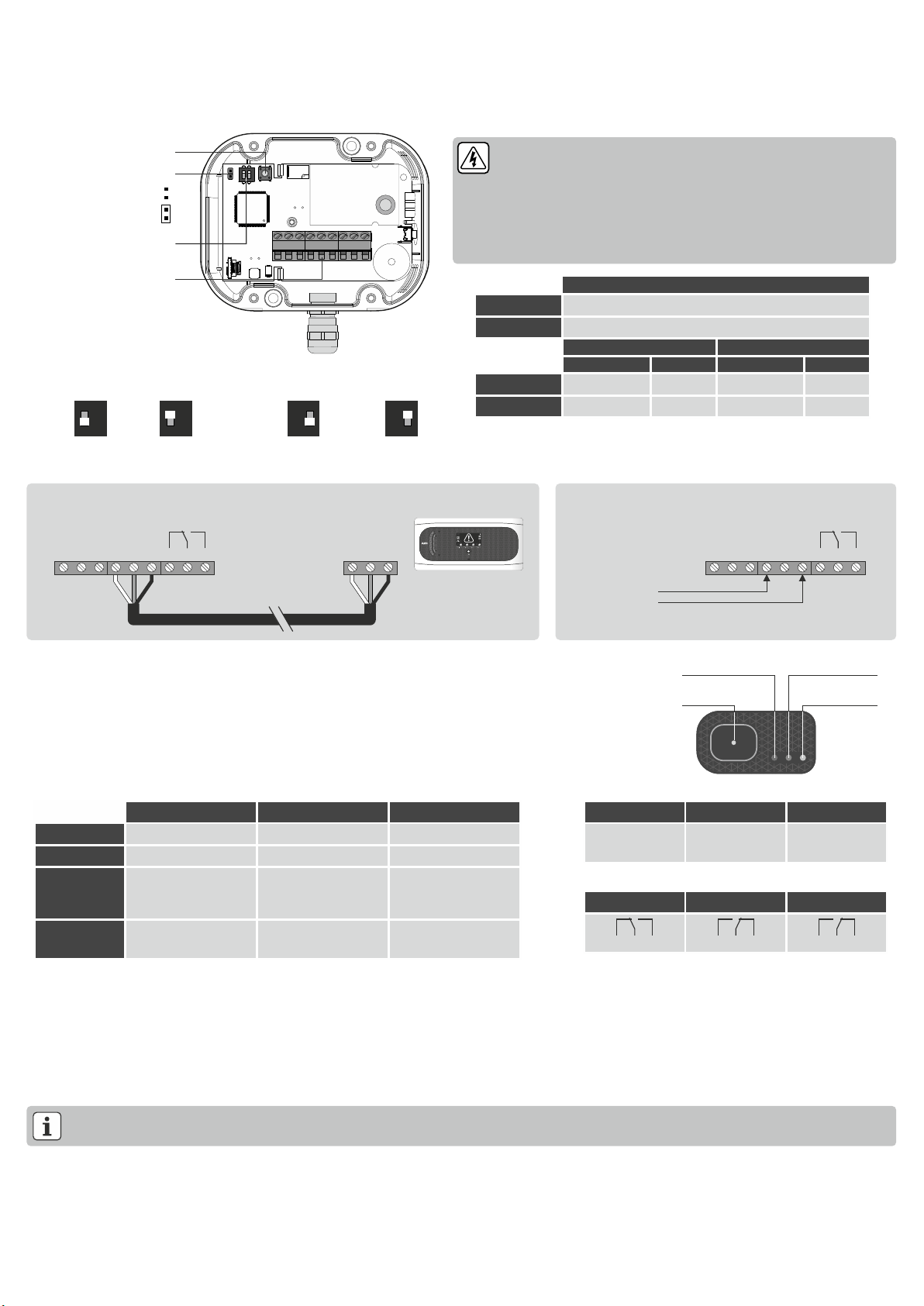
Technical specifications
Power supply ...............................................................................................................................................................12-30 Vdc
Consumption........................................................................................................................... Typical: 75 mA, Maximum:150 mA
Alarm relay .........................................................................................................................................SPDT 30 Vdc, 2A, cos j =1
Working ambient temperature....................................................................................................................................-20 to 50 ºC
Storage ambient temperature.....................................................................................................................................-20 to 60 ºC
Range of moisture permitted...................................................................................................0 - 95 % RH (Without condensation)
Protection degree With cable entry using cable gland .............................................................................................................IP68
With cable entry from the back ...................................................................................................................IP40
Dimensions..........................................................................................................................107 mm (W) x 85 mm (H) x 39 mm (D)
Complies with the EN 14624 standard.
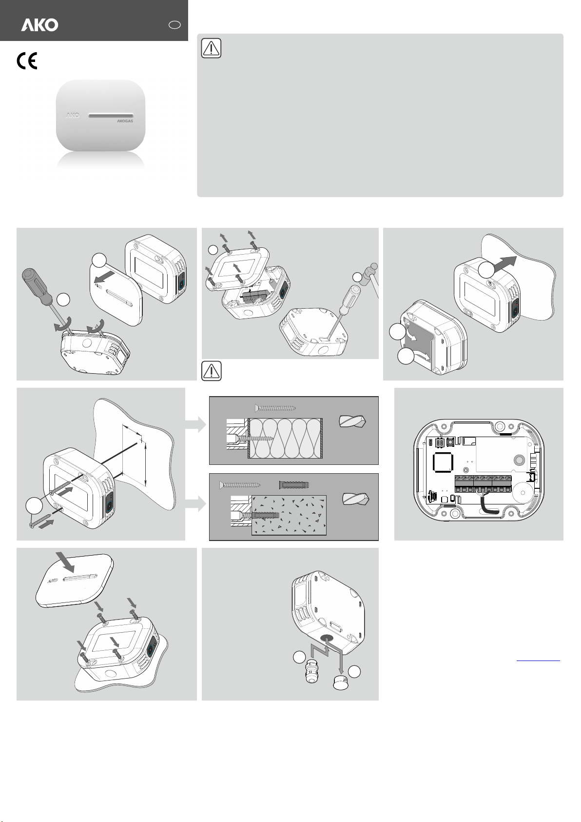
Installation
2
1
Opción B
Fixed by screws
36 mm
70 mm
3
1
2
With cable entry using cable gland
3.3
3.1
3.2
Option A
Fixied by an
adhesive
4
3
x2
Ø 2,8 mm
Ø 5 mm
x2
+
Connect following the
diagrams
Carefully perforate the rear entry so as not to damage
the electronic board.
This option involves changing from IP68 to IP40.
If the cable entry at the
back has not been drilled,
this option provides the
IP68 rating.
AKO-576410 AKO-576032
Red
Green
Blue
OFF
No alarms
Detector turned off
A levels active
ON
Alarm / Pre-Alarm activated
Standard operation
B levels active
Flashing*
Alarm / Pre-Alarm saved
Standard operation, acoustic
alarm disabled
MAINTENANCE mode
activated
Flash*
Detector error
Detector in initialisation
process
SET HOLD mode activated
Pre-Alarm
Alarm
Sensor error
Intermittent
sound
Bi-tonal
sound
3 tones
every 2 minutes
Description
Refrigerant gas detector, which can be used in independent operation or connected to alarm stations AKOCam, AKOAlarm and AKOGas.
Independent detector: The detector makes a certain warning sound in the event of an Alarm, Pre-Alarm or sensor error and the red indicator lights up (See operation section).
Detector connected to the alarm station: The detector notifies the station of its status (Alarm, Pre-Alarm or sensor error) and the station notifies the alarm through sound and indicators (for
further information consult the station's manual).
Pre-alarm jumper
Configuration push-button
Connection strip
Delay and alarm
levels configuration
Pre-alarm enabled
Pre-alarm disabled
Alarm delay
C C
NC NCNO NO
Gas
Alarm
Tr-
Tr-
Tr+
Tr+
Gnd
Gnd
RS485 RS485
Alarm Alarm
15V
15V
S
S
Gnd
Gnd
Red: Alarms Green:
Operation
Mute
push-button Blue: Operating
mode
Operation
Mute push-button
In the event of an Alarm or Pre-Alarm in process, any push-button press silences the Alarm/Pre-Alarm tone.
Any push-button press deletes saved alarms.
Medium press (between 3 and 9 sec.): It activates or deactivates the SET-HOLD mode. Should there be a sensor error, reset the detector.
Long press (> 9 sec.): It activates or deactivates the MAINTENANCE mode. Should there be a sensor error, reset the detector.
Configuration
In this mode the acoustic alarm can be activated / deactivated or the detector can be returned to factory settings.
To activate it:
1.- Disconnect the power supply, reconnect it and press the “CONFIGURATION” push-button 5 times within 2 minutes; the detector will emit a confirmation beep and the blue indicator will show the
status of the acoustic alarm: ON: Acoustic alarm enabled / Flashing: Acoustic alarm disabled.
2.- Press the Mute push-button to enable / disable the acoustic alarm.
3.- Press the “CONFIGURATION” push-button for 5 seconds to save the changes and exit the configuration mode; the detector will make 5 short beeps.
Optionally, you can return the detector to its factory settings. To do so, press the “CONFIGURATION” push-button 5 times before step 3.
Pre-alarm jumper
Allows for Pre-alarm detection to be enabled / disabled. Before using this option, ensure that regulations allow for two alarm levels.
SET-HOLD mode
Prevents false alarms when charging or cleaning the chambers. While this mode is activated, pre-alarms will not signal and alarms will signal as pre-alarms when faced with all effects (sound, relay
activation and signalling). This mode will remain active for a maximum of 5 hours, then will deactivate automatically.
Maintenance mode
Disables gas pre-alarms and alarms for 1 hour for maintenance tasks. While this mode is activated, no gas pre-alarm or alarm will sound.
*Flashing: 0.5 s ON / 0.5 s ON / Flash: 0.1 s ON / 0.8 s OFF
Audible alarm
Alarm relay
Pre-Alarm
Alarm
Sensor error
CNC NO CNC NO CNC NO
Connection to alarm station
Alarm station
15V
In
Gnd
Input x
GAS
Independent operation
12 - 30 Vdc
Without
delay
ON
1 2
ON
1 2
180 s
Alarm levels
A
levels
ON
1 2
ON
1 2
B
levels
Always disconnect the power supply to do the wiring.
The wiring between the detector/transmitter and the station should NEVER be installed in
a conduit together with power, control or supply cables.
Cables for wiring the relay contact should have an adequate section depending on the unit
to be connected.
Certain international standards maintain that the power supply of the alarm should
originate from a different circuit to that used by the refrigeration and ventilation system.
Please ensure that you comply with current local regulations.
Indicators
Wiring
*Factory configuration
GASES DETECTED
AKO-576410
R-410A
AKO-576032
R-32
A LEVELS
B LEVELS *
PRE-ALARM
ALARM
PRE-ALARM
ALARM
AKO-576410
500 ppm
1000 ppm
1500 ppm
3000 ppm
AKO-576032
500 ppm
1000 ppm
1000 ppm
2000 ppm

This manual suits for next models

1

Other AKO Gas Detector manuals

AKO AKO-575744NR User manual

AKO

AKO AKO-575744NR User manual

AKO AKO-52201 User manual

AKO

AKO AKO-52201 User manual

AKO AKO-57624 User manual

AKO

AKO AKO-57624 User manual

AKO 52201 User manual

AKO

AKO 52201 User manual

AKO AKO-575744NR User manual

AKO

AKO AKO-575744NR User manual

AKO 57624 User manual

AKO

AKO 57624 User manual

AKO AKO-57625 User manual

AKO

AKO AKO-57625 User manual

AKO AKO-522014 User manual

AKO

AKO AKO-522014 User manual

AKO AKO-5761 Series User manual

AKO

AKO AKO-5761 Series User manual

AKO AKO-57625-1 User manual

AKO

AKO AKO-57625-1 User manual

Popular Gas Detector manuals by other brands

STATUS SCIENTIFIC CONTROLS FGD4 Installation, Commissioning & Routine Gas Testing Manual

STATUS SCIENTIFIC CONTROLS

STATUS SCIENTIFIC CONTROLS FGD4 Installation, Commissioning & Routine Gas Testing Manual

GMI PS500 User handbook

GMI

GMI PS500 User handbook

OneTemp GDA 2500 Series operating manual

OneTemp

OneTemp GDA 2500 Series operating manual

Riken Keiki GADMS Lite operating manual

Riken Keiki

Riken Keiki GADMS Lite operating manual

Riken Keiki 70D Series Communication Function Manual

Riken Keiki

Riken Keiki 70D Series Communication Function Manual

CPVan CP-WG01W user guide

CPVan

CPVan CP-WG01W user guide

LANDTEC SEM5000 user guide

LANDTEC

LANDTEC SEM5000 user guide

FORENSICS DETECTORS FD-CO2000 quick start guide

FORENSICS DETECTORS

FORENSICS DETECTORS FD-CO2000 quick start guide

Taichuan HM-710 manual

Taichuan

Taichuan HM-710 manual

GasDog 41547 manual

GasDog

GasDog 41547 manual

Smartwares RM400 user manual

Smartwares

Smartwares RM400 user manual

Evikon PluraSens E2608-LEL user manual

Evikon

Evikon PluraSens E2608-LEL user manual

AP NH3 manual

AP

AP NH3 manual

brennenstuhl BCN 1221 Directions for use

brennenstuhl

brennenstuhl BCN 1221 Directions for use

Geca GAMMA Series manual

Geca

Geca GAMMA Series manual

CBE MTCO user manual

CBE

CBE MTCO user manual

Trotec BG30 operating manual

Trotec

Trotec BG30 operating manual

Tokyo Gas Engineering Solutions Corporation LaserMethane SMART LM2B03E-SBA operating instructions

Tokyo Gas Engineering Solutions Corporation

Tokyo Gas Engineering Solutions Corporation LaserMethane SMART LM2B03E-SBA operating instructions

manuals.online logo
manuals.online logoBrands
  • About & Mission
  • Contact us
  • Privacy Policy
  • Terms and Conditions

Copyright 2025 Manuals.Online. All Rights Reserved.