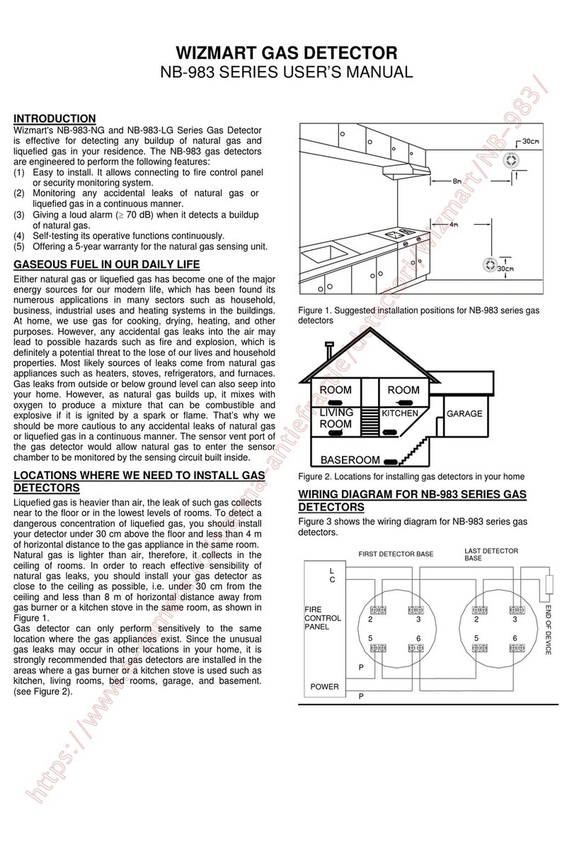
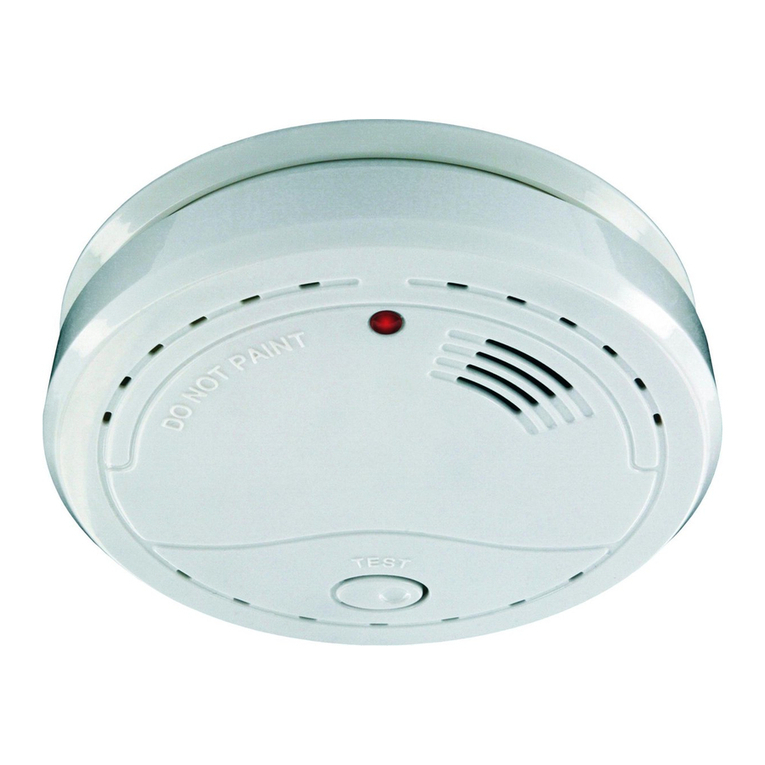
Wizmart NB983 User manual

wizmart
NB983 Non-addressable gas detector
Installation instructions
www.wizmart.com 1 32-0049-r01_2013-12
Cautions
ELECTRICAL HAZARD: Disconnect power from equipment prior
to making any internal adjustments. Service should only be
performed by qualified personnel.
FRAGILE: Inspect the equipment prior to installation. Do not
install the equipment if damage is apparent. Do not attempt to
disassemble this equipment. If damaged, return to the supplier.
ELECTROSTATIC HAZARD: This is sensitive electronic
equipment. Apply safe ant-static practices when handling this
equipment.
CIRCUIT LIMITATIONS: The maximum number of detectors
connected to a single detection zone is limited by the control and
indicating equipment, and may be limited by local regulations.
Introduction
NB983 non-addressable gas detectors are state-of-the-art
detectors suitable for connection to 4-wire non-
addressable fire detection control and indicating
equipment, or to 4-wire addressable fire detection control
and indicating equipment that can accept non-
addressable type detectors
1
.
These instructions provide trained installation personnel
with details to install and commission NB983 detectors for
optimum performance.
Preparation
Before commencing installation, ensure all equipment
(base and detector) and tools to mount and connect the
equipment are available, such as drills, mounting screws,
cables and ladders.
NB983 detectors can be installed with the following bases
and accessories.
Description Part
number Datasheet
8-term. 100 mm low profile base 774912 31-0003
8-term. 100 mm low profile base 774914 31-0003
8-term. 100 mm high profile base 884912 31-0003
8-term. 150 mm low profile base 784914 31-0003
27 mm recessed mounting ring 775912 31-0003
Zone monitor NB773 31-0056
Installation
Base
The base can be mounted directly onto an electrical
junction box such as an octagonal (75 mm, 90 mm or
100 mm), a round (75 mm), or a square (100 mm) box
without using any type of mechanical adapter.
1. Feed the conductors through the middle of the base
for termination to the base contacts.
2. Mount the base on the junction box or directly onto a
flat surface.
3. Mount the base to the surface using fixing screws
that are suitable to securely fix the base to the
surface.
1
May be used in conjunction with the NB773 zone monitor
module.
Wiring
The terminals of the base will accept 0.4 mm
2
to 2.5 mm
2
conductors.
1. Strip the conductor insulation to expose 5 mm of the
conductor.
2. Connect the conductors to the base terminals (see
Fig. 1).
WARNING: Take care to ensure the insulation does not
get clamped by the terminal contact.
Fig. 1: 4-wire base wiring connections
WARNING: Do not short-circuit terminals 2 and 5.
3. After all the bases are installed and wired, fit the end-
of-line resistor.
Note: The value of the end-of-line resistor depends on the control
and indicating equipment to which the detectors are installed.
4. Check the wiring for continuity, short circuits and
earth faults.
Output Relay
The output relay is factory-adjusted with normally-open
contacts that close on alarm. The relay can be configured
for normally-closed operation as follows.
1. Insert a screwdriver into the rectangular hole
located on the side between the detector front
cover and the body (see Fig. 4) and rotate to
remove the front cover.
2. Remove the jumper header located adjacent to the
relay, and reinsert it in the NC position (see Fig. 2
or Fig. 3).
3. Carefully replace the front cover.
Fig. 2: Adjusting the output relay – NB983-CO

wizmart
2 32-0049-r01_2013-12
Wizmart Technology Inc. 2F, 41-2, Sec 1, Chang-an East Road, Taipei 104, Taiwan
© 2013 Wizmart Technology Inc. All rights reserved. All specifications and other information shown were current at the date of publication and
subject to change without notice.
Fig. 3: Adjusting the output relay – NB983-LP and NB983-NG
Detector
WARNING: Do not install the detector head until the area
is thoroughly cleaned of construction debris, dust, etc.
1. Align the components as shown in Fig. 4.
2. Mate the detector head onto the base and rotate it
clockwise to secure it. The home alignment mark
should be aligned with the detector mark.
Fig. 4: Fitting the detector to the base
Commissioning
Equipment
WARNING: Test gases can kill. Use only a purpose-
designed test gas source, pipe and hood for testing. Be
sure to comply with safe handling and use requirements.
Ensure there are no naked flames within the test area.
Gas Detector
1. Ensure all the alarm signal services, releasing devices
and extinguisher systems are disabled during the
commissioning period.
2. Connect power to the detector for approximately
10 min.
3. During the start-up time, check that the green LED
flashes every 0.5 s. If the LED fails to light, it indicates
the detector is not operating. Check the wiring for the
correct voltage and earth leakage. Replace the
detector if necessary.
4. At the end of the start-up time, check that the green
LED lights continuously.
5. Cover the detector with a test hood and release the
test gas for at least 10 s from a test source.
6. When sufficient gas has entered the chamber, the
detector will signal an alarm, by continuous flashing of
the red LED and activation of the internal sounder.
7. Upon alarm, immediately remove the gas source.
8. Wait for the gas to clear and the detector to
automatically reset. The LED will change to green and
the sounder will silence.
9. If the alarm signal is latched at the control and
indicating equipment, reset the control and indicating
equipment.
Hush
1. Cover the detector with a test hood and release the
test gas for at least 10 s from a test source.
2. When sufficient gas has entered the chamber, the
detector will signal an alarm, by continuous flashing of
the red LED and activation of the internal sounder.
3. Upon alarm, immediately remove the gas source and
place a magnet adjacent to the cover of the detector
(see Fig. 2 or 3 for location).
4. Check that the detector enters the Hush condition, the
LED is red and sounder is silenced.
Output Relay
1. Activate the detector using the gas source, as
described above.
2. Monitor the output relay for activation.
3. Wait for the gas to clear and the detector to
automatically reset.
4. Monitor the output relay for reset to its quiescent
setting.
Reed Switch Test
1. Place a magnet adjacent to the cover of the detector
(see Fig. 2 or 3 for location).
2. Check that the detector signals an alarm, by
continuous flashing of the red LED and activation of
the internal sounder.
3. Remove the magnet and allow the detector to
automatically reset.
The auto-reset will typically reset the detector within 30 s
of the removal of the magnet.
Final Conditions
Ensure all the alarm signal services, releasing devices and
extinguisher systems disabled for the commissioning are
returned to their previous condition.
References
Document Description
31-0062 NB983 conventional (non-addressable) gas
detector datasheet
Limited Warranty
Wizmart Technology Inc. declares that this product is free from
defects in material and workmanship and it will repair or replace
any product or part thereof which proves to be defective in
workmanship or material for a period of twelve (12) months from
the date of purchase but not to exceed eighteen (18) months from
the date of manufacture. Please contact Wizmart Technology Inc.
directly for a return merchandise authorization (RMA) number
before returning goods under warranty. Shipment must be prepaid
and Wizmart Technology Inc. will repair or replace the product if
the failure was caused by a manufacturing defect.
View the complete range of
products at www.wizmart.com
Other Wizmart Gas Detector manuals
Popular Gas Detector manuals by other brands

ewoo
ewoo EW-403 Reference manual

BW Technologies
BW Technologies GasAlertMicroClip Quick reference guide

Consilium
Consilium Salwico KVD manual

Honeywell
Honeywell BW GasAlertMicro 5 user manual

olympia electronics
olympia electronics BS-694 quick start guide

brennenstuhl
brennenstuhl BCN 1221 Directions for use

CGS
CGS Merlin 1500S Installation & operation manual

TELEDYNE OLDHAM SIMTRONICS
TELEDYNE OLDHAM SIMTRONICS Everywhereyoulook GD10-P00 operating manual

Critical Environment Technologies
Critical Environment Technologies GEM-II Operation manual

Honeywell
Honeywell BW Icon user manual

Alecto
Alecto COA4010 manual

LEGRAND
LEGRAND Galea Life 7756 78 manual