industrie technik TPDA-12A User manual

INSTRUCTION
i
Read this instruction before installation
and wiring of the product
Instruction TPDAxxxxAx 1
TPDAxxxxAx
Pressure transmitter
TPDA...A are single or dual port pressure transmitters with one or two
universal outputs for 0...10 V or 4...20 mA (selectable).
Technical data
Supply voltage 24 V AC/DC ±15 %
Protection class IP54
Calculated power consumption
0...10 V mode 2 VA (rms) / min. trafo size 7.5 VA
4...20 mA mode 2.7 VA (rms) / min. trafo size 9 VA
Overall accuracy, pressure ≤ 1 % full scale
Annual deviation (typical)
P1250 models ±2 Pa
P2500 models ±4 Pa
P7500 models ±20 Pa
Damping (settable) 1, 2, 4 and 8 s
Operating temperature range -25…+50°C
Operating humidity Max.95 % RH (non-condensing)
Overvoltage on any terminal Max. ±18 V (referenced to GND)
Universal outputs PS1, PS2
Congured as 0...10 V Load impedance ≥ 10 kΩ,
Output impedance ≤ 35Ω
Congured as 4...20 mA Output is actively sourced into a resistive
load impedance to signal ground. The
load impedance must be between
40...500Ω
Pressure ranges (full scale)
Model Pressure
range (Pa)
mBar mmH2O inH2O
TPDA-12A PS1 0…1250 0…12.5 0…125 0…5
TPDA-25A PS1 0…2500 0…25 0…250 0…10
TPDA-75A PS1 0…7500 0…75 0…750 0…30
TPDA-1225A2 PS1 0…1250 0…12.5 0…125 0…5
PS2 0…2500 0…25 0…250 0…10
TPDA-1275A2 PS1 0…1250 0…12.5 0…125 0…5
PS2 0…7500 0…75 0…750 0…30
Note: The sufx in the name denotes the number of sensors in the unit.
The sufx “-2” indicates two sensors. No sufx means one sensor only.
Installation
The transmitter comes with one cable gland mounted and one loose. If
two cables are used, one for supply voltage and one for output signals,
the other cable gland must be assembled to the housing. Screw in the
cable gland until the plastic knockout in the housing snaps. Make sure to
remove the plastic knockout completely. Secure the cable gland.
1. Mount the transmitter horizontally or vertically on a stable,
vibration-free surface. If the unit is installed in a humid environ-
ment, install it vertically with the cable gland edge of the unit
pointing down to allow moisture to escape.
Take extra care when connecting the hoses to the inlet ports, as
the thin inner connections of the inlets are very sensitive. The lid
should be kept closed while performing the connections, or the
thin tubing might detach from the sensor.
2. Refer to the graphics below for wiring. Use the leftmost cable
gland for supply voltage and use the rightmost gland for output
signals in order to minimise crosstalk between supply wires and
signal wires.
3. Set the DIP-switch to the desired operational mode and param-
eters.
4. Power up the unit.
5. Let the unit warm up for 10 minutes, then perform a zero-set
calibration by pressing the pushbutton.
6. Connect plastic tubes from the ventilation duct to the pressure
inlets.
NOTE: A straight cut off nipple must be used for mounting in the
ventilation duct.
For optimal measuring results, measuring points with turbulent air
ow should be avoided. Preferably, measuring should be performed
at a distance of 2 duct diameters before bends and branching and at
6 duct diameters after bends and branching.
Wiring
1. G (+)
2. G0 (-)
3. UO1 +
4. UOI GND
5. UO2 +
6. UO2 GND
Terminals 2, 4 and 6 are galvanically the same (GND/G0).
For models with two sensors, the leftmost DIP-switch controls sensor
1 and the rightmost DIP-switch controls sensor 2 (see diagram 2
below).
12632 C
JUL 17
EN

Instruction TPDAxxxxAx 2
1
6
ON
1
5
4
3
2
1 2 3 4
AO1
+
0...10 V
or
4...20 mA
Pushbutton
Status LEDs
DIP-switch
Sensor 1
24V AC/DC
or DC ±15 %
+
-
Wiring for models with one sensor
1
6
ON
1
6
ON
1
5
6
4
3
2
1 2 3 4 5 6
24V AC/DC
or DC ±15 %
+
-
AO1
AO2
+
+
0...10 V
or
4...20 mA
Pushbutton
Status LEDs
DIP-switches 1 (left) and 2 (right)
Sensor 1
Sensor 2
Wiring for models with two sensors
DIP-switches
The transmitter features one or two DIP-switches for setting up suit-
able pressure range, output function and damping time factor.
If the DIP-switch settings are changed, all changes will take place
immediately.
If a factory reset is performed, the pressure sensors will be reset to
the factory calibration.
DIP-
switch
Parameter Key pattern Parameter
setting
1 Output
function
OFF 0...10 V *
ON 4...20 mA
2, 3
and 4
Pressure
range
2 = OFF, 3 = OFF, 4 = OFF Range 1 *
2 = ON, 3 = OFF, 4 = OFF Range 2
2 = OFF, 3 = ON, 4 = OFF Range 3
2 = ON, 3 = ON, 4 = OFF Range 4
2 = OFF, 3 = OFF, 4 = ON Range 5
2 = ON, 3 = OFF, 4 = ON Range 6
2 = OFF, 3 = ON, 4 = ON Range 7
2 = ON, 3 = ON, 4 = ON Not used in
this version
5 and
6
Damping
time factor
5 = OFF, 6 = OFF 1 s *
5 = ON, 6 = OFF 2 s
5 = OFF, 6 = ON 4 s
5 = ON, 6 = ON 8 s
Table 1
* Factory setting
Pressure ranges
DIP-switches 2, 3 and 4 are used to select the current pressure range
of the transmitter (see above). Depending on the sensor model(s) in the
device, the different range settings will yield the following outputs (Pa):
Pressure
range
1250 Pa
sensor
2500 Pa
sensor
7500 Pa
sensor
Output
(Pa)
Range 1 0...50 0...100 0...1000
Range 2 0...100 0...300 0...2000
Range 3 0...300 0...500 0...3000
Range 4 0...500 0...1000 0...4000
Range 5 0...700 0...1500 0...5000
Range 6 0...1000 0...2000 0...6000
Range 7 0...1250 0...2500 0...7500
Table 2
Pushbutton
Quick press: Zero-set pressure sensors.
Disconnect the pressure ports before zeroing. Let the unit warm up for
10 minutes before attempting the procedure. Zeroing usually takes a few
seconds. The yellow LED will light up while the zeroing operation is in
progress.
If the yellow LED starts blinking during the zeroing procedure, the unit
has failed to zero-set properly. If so, ensure that the pressure ports
are open and unobstructed and then power-cycle the unit and try
again.
If the procedure still fails, a sensor error is present and the unit must
then be replaced.
Long press (10 s): Reset to factory settings.
The red and yellow LEDs will ash alternating for the duration of the
operation. The unit will then reset and restart.
Status LED
The red status LED will light up at power-on and go out shortly there-
after when the on-board sensory circuitry is ready for operation.
Blinking red LED after power-up: The unit has lost important
system settings and must be taken back to the factory for reprogram-
ming.
Steady red LED during normal operation: The unit is damaged and
should be returned or discarded.
EMC emissions & immunity standards
This product conforms to the requirements of the EMC Directive
2014/30/EU through product standard 60730-1.
RoHS
This product conforms to the Directive 2011/65/EU of the European
Parliament and of the Council.
Contact
AB Industrietechnik srl - Via Julius Durst, 70
39042 BRESSANONE (BZ) Italy
Tel.: +39 0472/830626
[email protected], www.industrietechnik.it

Instruction TPDAxxxxAx 3
Trasmettitore di pressione
TPDA....A sono trasmettitori di pressione a porta singola o dop-
pia con uno o due uscite universali per segnali 0...10 V o 4...20 mA
(selezionabili).
Caratteristiche tecniche
Tensione di alimentazione 24 V AC/DC ±15 %
Classe di protezione IP54
Potenza assorbita calcolata
0...10 V-modalità 2 VA (rms) / potenza min. trasf. 7,5 VA
4...20 mA-modalità 2,7 VA (rms) / potenza min. trasf. 9 VA
Precisione complessiva, calcolata ≤ 1 % del fondo scala
Deriva annua (valore tipico)
P1250-modelli ±2 Pa
P2500-modelli ±4 Pa
P7500-modelli ±20 Pa
Smorzamento (impostabile) 1, 2, 4 och 8 s
Temperatura di funzionamento -25…+50°C
Umidità di funzionamento Max.95 % UR (senza condensa)
Sovratensione su qualsiasi terminale Max. ±18 V (rispetto a GND)
Uscite universali PS1, PS2
Congurati come 0...10 V Impedenza di carico ≥ 10 kΩ,
Impedenza di uscita ≤ 35Ω
Congurati come 4...20 mA Il carico resistivo deve essere
collegato tra l´uscita e il segnale di
massa e deve avere un valore
compreso fra 40...500Ωohm
Modelli e intervalli di pressione (fondo scala)
Modello Intervalli di
pressione (Pa)
mBar mmH2O inH2O
TPDA-12A PS1 0…1250 0…12,5 0…125 0…5
TPDA-25A PS1 0…2500 0…25 0…250 0…10
TPDA-75A PS1 0…7500 0…75 0…750 0…30
TPDA-1225A2 PS1 0…1250 0…12,5 0…125 0…5
PS2 0…2500 0…25 0…250 0…10
TPDA-1275A2 PS1 0…1250 0…12,5 0…125 0…5
PS2 0…7500 0…75 0…750 0…30
Nota: Il sufsso nel nome indica il numero di sensori nell’unità. Il sufsso
“-2” indica due sensori. Nessun sufsso signica un solo sensore.
Installazione
Il trasmettitore viene fornito con un pressacavo montato ed uno a parte
incluso nella confezione. Se si utilizzano due cavi, uno per la tensione di
alimentazione ed uno per i segnali di uscita, anche il secondo pressacavo
deve essere montato nell’apposito alloggiamento. Avvitare quest´ultimo
no a sfondare la parete di tenuta. Assicurarsi di rimuovere completa-
mente i residui all´interno dell´apparecchio. Serrare la ghiera del pres-
sacavo.
1. Montare il trasmettitore orizzontalmente o verticalmente su una
supercie stabile, esente da vibrazioni. Se l’unità è installata in
un ambiente umido, installarlo in verticale con il bordo pres-
sacavo dell’unità verso il basso per permettere all’umidità di
fuoriuscire.Fare particolare attenzione quando si collegano i tubi
alle porte di ingresso, dato che le sottili connessioni interne degli
ingressi sono molto sensibili. Il coperchio deve essere mantenu-
to chiuso durante l’esecuzione delle connessioni o il sottile tubo
potrebbe distaccarsi dal sensore
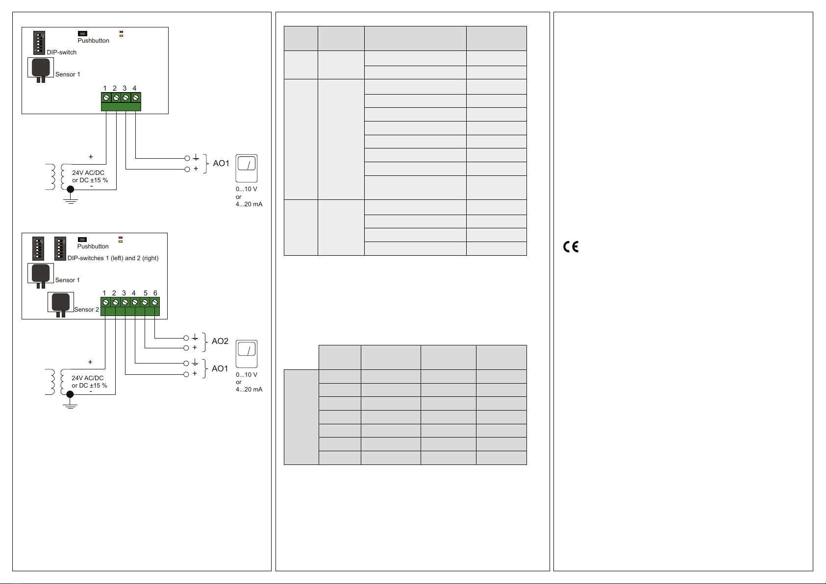
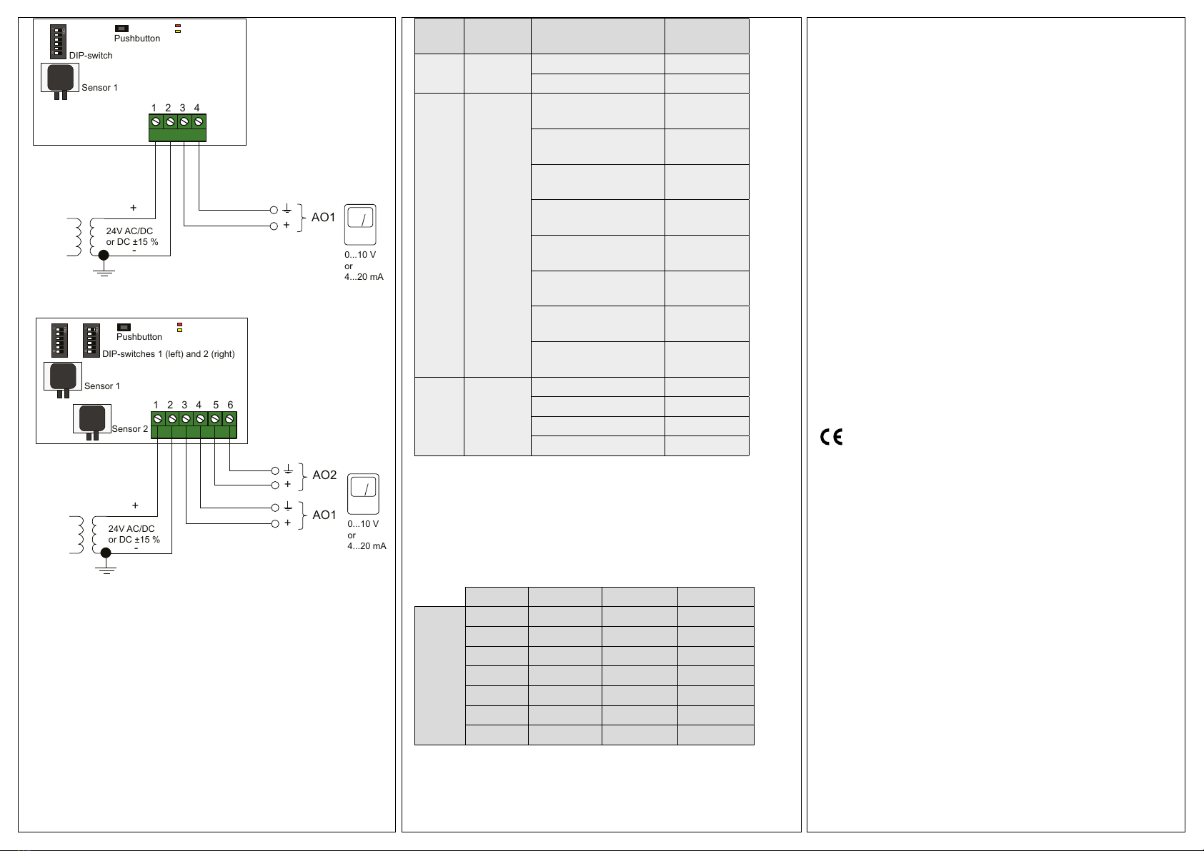
2. Fare riferimento alle immagini di seguito per il cablaggio. Utiliz-
zare il passacavo più a sinistra per la tensione di alimentazione
e utilizzare il pressacavo più a destra per i segnali di uscita al
ne di minimizzare le interferenze tra i cavi di alimentazione e
cavi di segnale.
3. Impostare il dip-switch per la modalità operativa desiderata ed i para-
metri.
4. Accendere l’unità.
5. Lasciare riscaldare l’unità per 10 minuti, quindi eseguire un
azzeramento premendo il pulsante.
6. Collegare i tubi di plastica dal condotto di ventilazione alle prese
di pressione.
NOTA: Per il montaggio nel condotto di ventilazione è necessario
utilizzare un nipplo a taglio dritto.
Per risultati ottimali di misurazione, evitare i punti di misura con
usso d’aria turbolento. Preferibilmente, la misurazione deve essere
effettuata a una distanza di 2 diametri di condotto prima di curve e
ramicazioni ed a 6 diametri di condotto dopo curve e ramicazioni.
Cablaggi
1. G (+)
2. G0 (-)
3. UO1 +
4. UOI GND
5. UO2 +
6. UO2 GND
I terminali 2, 4 e 6 sono galvanicamente gli stessi (GND / G0).
Per i modelli con due sensori, il DIP-switch più a sinistra controlla il
sensore 1 e quello più a destra controlla il sensore 2 (vedi gura 2).
i
Leggere le istruzioni prima di montare e cablare il
prodotto
ISTRUZIONI
TPDAxxxxAx
IT

Instruction TPDAxxxxAx
DIP-
switch
Parametri Settaggio pulsante Settaggio
parametri
1 Funzione
uscita
OFF 0...10 V *
ON 4...20 mA
2, 3
e 4
Scale di
pressione
2 = OFF, 3 = OFF,
4 = OFF
Scala 1 *
2 = ON, 3 = OFF,
4 = OFF
Scala 2
2 = OFF, 3 = ON,
4 = OFF
Scala 3
2 = NO, 3 = NO,
4 = OFF
Scala 4
2 = OFF, 3 = OFF,
4 = ON
Scala 5
2 = ON, 3 = OFF,
4 = ON
Scala 6
2 = OFF, 3 = ON,
4 = ON
Scala 7
2 = ON, 3 = ON,
4 = ON
Non utilizzato in
questa versione
5 och 6 Fattore di
tempo per
smorza-
mento
5 = OFF, 6 = OFF 1 s *
5 = ON, 6 = OFF 2 s
5 = OFF, 6 = ON 4 s
5 = ON, 6 = ON 8 s
Tabella 1
* Impostazioni di fabbrica
Intervalli di pressione
I DIP-switch 2, 3 e 4 sono utilizzati per selezionare l’intervallo di pressione
attuale del trasmettitore (vedi sopra). A seconda del modello del sensore
(s) nel dispositivo, i diversi intervalli produrranno le seguenti uscite (Pa):
Scala Sens. 1250 Pa Sens. 2500 Pa Sens. 7500 Pa
Uscita
(Pa)
Scala 1 0...50 0...100 0...1000
Scala 2 0...100 0...300 0...2000
Scala 3 0...300 0...500 0...3000
Scala 4 0...500 0...1000 0...4000
Scala 5 0...700 0...1500 0...5000
Scala 6 0...1000 0...2000 0...6000
Scala 7 0...1250 0...2500 0...7500
Tabella 2
Pulsanti
Pressione rapida: Calibrazione a zero dei sensori di pressione.
Scollegare le prese di pressione prima dell’azzeramento. Lasci-
are riscaldare l’unità per 10 minuti prima di eseguire la procedura.
L`azzeramento di solito richiede pochi secondi. Il LED giallo si ac-
cende durante l’operazione di azzeramento.
Se il LED giallo inizia a lampeggiare durante la procedura di azzera-
mento, l’unità non è riuscita ad azzerarsi correttamente. Se così
fosse, assicurarsi che le porte di pressione siano aperte e senza
ostruzioni, quindi spegnere e riaccendere l’unità e riprovare.
Se la procedura non riesce ancora, è presente un errore del sensore
e l’unità deve quindi essere sostituita.
Pressione prolungata (10 s): Ripristino impostazioni di fabbrica.
I LED rosso e giallo lampeggiano alternati per la durata
dell’operazione. L’unità quindi si ripristinerà e riavvierà.
LED di stato
Il LED di stato rosso si accende all’accensione e si spegne poco dopo
quando il sistema è pronto per il funzionamento.
LED lampeggiante rosso dopo l’accensione: L’unità ha perso
importanti impostazioni di sistema e deve essere riportato in fabbrica
per la riprogrammazione.
LED rosso sso durante il normale funzionamento: l’unità è dan-
neggiata e deve essere restituita o scartata.
Emissioni EMC e standard di immunità
Questo prodotto è conforme ai requisiti della Direttiva EMC
2014/30 / EU attraverso le norme di prodotto 60730-1.
RoHS
Questo prodotto è conforme alla direttiva 2011/65 / UE del
Parlamento europeo e del Consiglio.
Contatti
AB Industrietechnik srl - Via Julius Durst, 70
39042 BRESSANONE (BZ) Italy
Tel.: +39 0472/830626
[email protected], www.industrietechnik.it
4
1
6
ON
1
5
4
3
2
1 2 3 4
AO1
+
0...10 V
or
4...20 mA
Pushbutton
Status LEDs
DIP-switch
Sensor 1
24V AC/DC
or DC ±15 %
+
-
Cablaggio per modelli a 1 sensore
1
6
ON
1
6
ON
1
5
6
4
3
2
1 2 3 4 5 6
24V AC/DC
or DC ±15 %
+
-
AO1
AO2
+
+
0...10 V
or
4...20 mA
Pushbutton
Status LEDs
DIP-switches 1 (left) and 2 (right)
Sensor 1
Sensor 2
Cablaggio per modelli a 2 sensori
DIP-switch
Il trasmettitore è dotato di uno o due DIP-switch per l’impostazione
del campo di pressione adatto, della funzione di uscita e del fattore di
smorzamento.
Se le impostazioni DIP-switch vengono modicate, tutte le modiche
avranno luogo immediatamente.
Se viene eseguito un reset di fabbrica, i sensori di pressione ver-
ranno ripristinati alla calibrazione impostata in fabbrica.
This manual suits for next models
4
Table of contents
Languages:
Other industrie technik Transmitter manuals
Popular Transmitter manuals by other brands

Kramer
Kramer TP-185 user manual

Vega
Vega VEGABAR 66 operating instructions

Avtek
Avtek Share quick guide

Pfeiffer Vacuum
Pfeiffer Vacuum CPT 100 operating instructions

Cobalt Digital Inc
Cobalt Digital Inc BlueBox BBG-OE-MK2 Fiber-To-Coax quick start guide

Inovonics
Inovonics EN1722 installation instructions