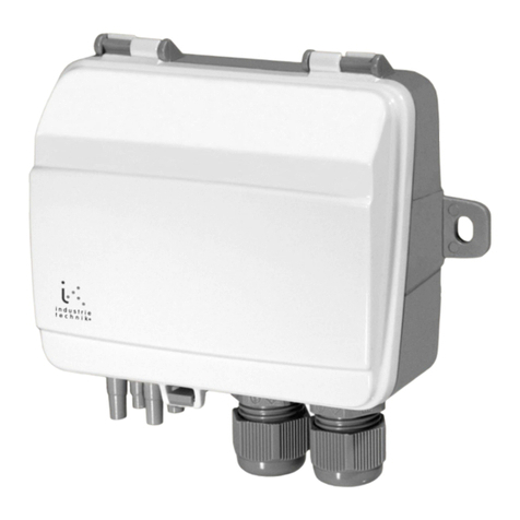
industrie technik TVAN User manual

INSTRUCTION
TVAN
i
Read this instruction before
installation and wiring of the product.
Consult documentation in all cases where this symbol
is used, in order to nd out the nature of the potential
hazards and any actions to be taken
1
TVAN
Drill a <Ø16 mm hole in the duct wall. For optimal measuring results,
measuring points with turbulent air ow should be avoided. Preferably,
measuring should be performed at a distance of 2 duct diameters before
bends and branching and at 6 duct diameters after bends and branching.
<16 mm
60 mm
Air velocity
Hold the ange against the hole and drill fastening holes using the ange
as template. Fasten the ange.
Mount the sensor stem through the hole in the ange and x it at desired
depth.
Immersion length
30 - 50 % of pipe diameter
Air velocity
INCORRECT
CORRECT
It is also possible to mount the sensor using the screw-pockets in the
sensor housing.
In both cases it is essential to position the sensor so that there can be an
unobstructed, straight airow past the sensor element.
Wiring
Connect supply voltage and output signal according to the diagram
below.
t90
HI
MED
LO
I
U
t90
HI
MED
LO
I
U
t90
HI
MED
LO
I
U
t90
HI
MED
LO
I
U
t90
HI
MED
LO
I
U
t90
HI
MED
LO
I
U
t90
HI
MED
LO
I
U
Output
Working range
Response time
No jumper
Jumper
Jumper
Jumper
Jumper
FAST approx. 0.7
s
Jumper
Current (I)
Jumper
Voltage (U)
= factory setting
= factory setting
= factory setting
0...10 m/s
0...15 m/s
0...20 m/s
SLOW approx. 4 s
The output signal, working range and response time are selected by
the jumpers according to the picture above.
The response time is normally set to 4 seconds. By removing the
jumper it is shortened to 0.7 seconds.
Maintenance
Should the element become very dirty it can be blown clean using a
soft air-jet or be rinsed in isopropyl alcohol.
12807A
DEC 16
EN
1 Supply voltage 24 V AC
2 System neutral
3 0...10 V or 4...20 mA
Duct mounted air velocity transmitter
TVAN is a duct mounted air velocity transmitter for measuring air
velocity in air handling systems.The air velocity sensor operates on
the hot-wire anemometer principle.
The output can be set to 0...10 V or 4...20 mA.
Different measuring ranges for full output signal can be set to give the
best possible accuracy.
There is a choice of two different response times for the output signal.
Installation
It is important that the unit is mounted so that the direction of the
sensor head opening corresponds to the direction of the air ow (an
arrow indicating the ow direction is shown inside the housing).
Air velocity Air velocity
Correct Incorrect

TVAN 2
Technical Data
Supply voltage 24 V AC/DC ± 20 %
Power consumption 5 VA
Wiring Screw terminals
Ambient temperature -10...+50°C
Storage temperature -30...+50°C
Time constant 1,5 s at 10 m/s
Protection class IP65
Inputs
Sensor element Thin lm element
Working range 0...10 / 0...15 / 0...20 m/s, selectable
Accuracy
Range 0.2...10 m/s ±(0.2 m/s + 3% of value)
Range 0.2...15 m/s ±(0.2 m/s + 3% of value)
Range 0.2...20 m/s ±(0.2 m/s + 4% of value)
Response time Selectable 0.7 or 4 s
Outputs
Output 0...10V DC or 4...20 mA, selectable
External load impedance
0...10 V output signal > 10 kΩ
4...20 mA output signal < 500 Ω
EMC emissions & immunity standards
This product conforms to the requirements of the EMC Directive
2014/30/EU through product standards EN 61326-1 and
EN 61326-2-3.
RoHS
This product conforms to the Directive 2011/65/EU of the European
Parliament and of the Council through standard EN 50581:2012.
Contact
AB Industrietechnik srl - Via Julius Durst, 70
39042 BRESSANONE (BZ) Italy
Tel.: +39 0472/830626
[email protected], www.industrietechnik.it
Trasmettitore di velocitá dell´aria da condotta
TVAN è un trasmettitore di velocità dell’aria da condotta utilizzato per
la misurazione della velocità del usso nelle unitá di trattamento aria.Il
funzionamento del trasmettitore si basa sul principio dell’anemometro a
lo caldo.
L’uscita può essere impostata a 0 ... 10 V o 4 ... 20 mA.
Per garantire la massima precisione a diverse velocità, è possibile impo-
stare tre diversi campi di misura riferiti al segnale di uscita.
È possibile scegliere tra due tempi di risposta del segnale di uscita differenti.
Installazione
É importante che l’unità sia montata in modo tale che la direzione dell’apertura
della testa del sensore corrisponda alla direzione del usso d’aria (all´interno
della custodia é rafgurata una freccia che indica il senso del usso).
Praticare un foro da Ø16 mm nella parete del canale. Per misurazioni
ottimali, rilevazioni in prossimitá di ussi d´aria turbolenta dovrebbero
essere evitati. Preferibilmente, la misurazione deve essere eseguita ad
una distanza di 2 diametri condotto prima di una curva/ramicazione e a 6
diametri condotto dopo una curva/ramicazione.
Tenere la angia contro il foro e praticare i fori di ssaggio con la
angia come modello.
Fissare la angia.Montare lo stelo del sensore attraverso il foro della
angia e ssarlo alla profondità desiderata.
È possibile, inoltre, montare il trasmettitore utilizzando i fori per viti sul
contenitore.
In entrambi i casi è fondamentale posizionare l’apparecchio in modo
che il usso d’aria attraverso l’elemento sensore sia diretto e libero da
ostacoli.
ISTRUZIONI
TVAN
Consultare la documentazione per tutti i casi in cui
viene utilizzato il simbolo per individuare la natura
dei potenziali rischi e le azioni da intraprendere
IT
CORRETTO ERRATO
Velocitá aria lunghezza di inserimento
30 - 50 % del diametro tubo
Corretto Errato
Velocitá aria Velocitá aria
<16 mm
60 mm
Velocitá aria

TVAN 3
Cablaggio
Collegare la tensione di alimentazione e il segnale di uscita come
da schema.
Il segnale di uscita, la scala di lavoro ed il tempo di risposta vengono
selezionati tramite jumper come riportato nell’immagine sopra.
Il tempo di risposta normalmente è impostato a 4 secondi.
Rimuovendo il jumper viene ridotto a 0,7 secondi.
Manutenzione
Nel caso in cui l’elemento dovesse sporcarsi, è possibile pulirlo me-
diante un getto d’aria delicato o con alcol isopropilico.
1 Alimentazione 24 V AC
2 Comune/GND
3 Uscita 0...10 V o 4...20 mA
Caratteristiche tecniche
Tensione di alimentazione 24 V AC/DC ± 20 %
Potenza assorbita 5 VA
Attacchi Morsetti a vite
Temperatura ambiente -10...+50°C
Temperatura di stoccaggio -30...+50°C
Costante di tempo 1,5 s a10 m/s
Classe di protezione IP65
Ingressi
Elemento sensibile Film sottile
Scala di lavoro 0...10 / 0...15 / 0...20 m/s, selezionabile
Precisione
Scala 0.2...10 m/s ±(0.2 m/s + 3% del valore)
Scala 0.2...15 m/s ±(0.2 m/s + 3% del valore)
Scala 0.2...20 m/s ±(0.2 m/s + 4% del valore)
Tempo di risposta Selezionabile 0,7 o 4 s
Uscita
Uscite 0...10V DC o 4...20 mA, selezionabile
Impedenza esterna di carico
uscita 0...10 V
uscita 4...20 mA
> 10 kΩ
< 500 Ω
EMC Compatibilità elettromagnetica
Questo prodotto è conforme ai requisiti della Direttiva EMC 2014/30 / UE,
attraverso norme di prodotto EN 61000-6-1 e 61000-6-3.
RoHS
Questo prodotto è conforme alla direttiva 2011/65 / UE del Parlamento
europeo e del Consiglio tramite standard 50581 : 2012.
Contatti
AB Industrietechnik srl - Via Julius Durst, 70
39042 BRESSANONE (BZ) Italy
Tel.: +39 0472/830626
[email protected], www.industrietechnik.it
t90
HI
MED
LO
I
U
t90
HI
MED
LO
I
U
t90
HI
MED
LO
I
U
t90
HI
MED
LO
I
U
t90
HI
MED
LO
I
U
t90
HI
MED
LO
I
U
t90
HI
MED
LO
I
U
Uscita
Scala di lavoro
Tempo di risposta
No jumper
Jumper
Jumper
Jumper
Jumper
RAPIDO approx. 0.7 s
Jumper
Current (I)
Jumper
Voltage (U)
= impostazione di fabbrica
0...10 m/s
0...15 m/s
0...20 m/s
LENTO approx. 4 s
Table of contents
Languages:
Other industrie technik Transmitter manuals
Popular Transmitter manuals by other brands

Max Machinery
Max Machinery 276-5 Series instruction manual

Gates
Gates BC-1T Instructions for installing and operating

Honeywell
Honeywell ADEMCO 5801 Installation and setup guide

Endress+Hauser
Endress+Hauser AT1000 AT1 operating instructions

KLAY-INSTRUMENTS
KLAY-INSTRUMENTS 2000 Series instruction manual

HR Smith
HR Smith Techtest 503 Series Maintenance manual