infernus AP238-PS15 User manual

Professional Under Cabinet Range Hood
Model Name: AP238-PS15
Available Sizes: 36”, 42”, 48”, 60”
Rev.20230223
INSTALLATION GUIDE
AND USERS MANUAL

VICTORY range hoods
2| A Infernus range hoods
P238-PS15 VERONA / ELITE | 3
Important Safety Notice................................................................... 3
Calculating Duct System Length.................................................... 5
Specications................................................................................... 5
Required Tools.................................................................................. 6
PartsSupplied................................................................................... 6
Dimensions........................................................................................ 7
Preparation........................................................................................ 9
Installation ....................................................................................... 10
Grease Tunnel and Filters................................................................ 13
Venting Methods............................................................................... 14
Wiring Diagram................................................................................. 16
Range Hood Operations................................................................... 17
Troubleshooting................................................................................ 19
Do’s and Don’ts for Duct Venting.................................................... 20
Bulb Replacement............................................................................ 20
Maintenance...................................................................................... 21
Warranty............................................................................................. 22
Disclaimer.......................................................................................... 23
Contact Us........................................................................................ 23
TABLE OF CONTENTS

VICTORY range hoods
| VERONA / ELITE
2AP238-PS15 | 3
• The installation in this manual is intended for qualied installers, service technicians or persons with
similar qualied background. Installation and electrical wiring must be done by qualied professionals
and in accordance with all applicable codes and standards, including re-rated construction.
• DO NOT attempt to install this appliance yourself. Injury could result from installing the unit due to lack
of appropriate electrical and technical background.
• Range hood may have very sharp edges; please wear protective gloves if it is necessary to remove any
parts for installing, cleaning or servicing.
• Activating any switch ON before completing installation may cause ignition or an explosion.
• Due to the size and weight of this range hood, two-person installation is recommended.
To reduce the risk of re, electric shock, or injury to persons:
• For general ductilating use only. DO NOT use to exhaust hazardous or explosive materials and vapors.
• The combustion air ow needed for safe operation of fuel-burning equipment may be aected by this
unit’s operation. Follow the heating equipment manufacturer’s guideline and safety standards such as
those published by the National Fire Protection Association (NFPA), and the American Society of Heat-
ing, Refrigeration and Air Conditioning Engineers (ASHRAE), and the local code authorities.
• Before servicing or cleaning unit, switch power OFF at service panel and lock service panel to preduct
power from being switched ON accidentally.
• Clean grease laden surfaces frequently. To reduce the risk of re and to disperse air properly, make sure
to duct air outside. DO NOT duct exhaust into spaces between walls, crawl spaces, ceiling, attics and/
or garages.
• Ducted fans MUST always be ducted to the outdoors.
• Use only metal ductwork and this unit MUST be grounded.
• Sucient air is needed for proper combustion and exhausting of gases through the duct to preduct back
drafting.
• When cutting or drilling into wall or ceiling, be careful not to damage electrical wiring or other hidden
utilities.
• All electrical wiring must be properly installed, insulated and grounded.
• Old duct work should be cleaned or replaced if necessary to avoid the possibility of a grease re.
• Check all joints on duct work to insure proper connection and all joints should be properly taped.
• Use this unit only in the manner intended by the manufacturer. If you have questions, contact the vendor.
To reduce the risk of a stove top grease re:
• Keep all fans, spacers, lters, grease tunnels, oil containers and grease-laden surfaces clean. Grease
should not be allowed to accumulate on fan, bae, spaces, lter, grease tunnel and oil container.
• Always turn range hood ON when cooking at high heat or when cooking foods that produce ames.
• Use high settings on cooking range only when necessary.
• Never leave surface units unattended at high settings. Boil overs cause smoking and greasy spillovers
that may ignite. Heat oils slowly on low or medium settings.
IMPORTANT SAFETY NOTICE
Read all instructions before installing and operating this appliance
Infernus range hoods

VICTORY range hoods
4| AP238-PS15 VERONA / ELITE | 5
• Clean ductilating fan frequently.
• Always use appropriate cookware and utensils size.
• Always use cookware appropriate for the size of the surface element.
To reduce the risk of injury to persons in the educt of a stove top grease re:
• Smother ames with a close-tting lid, cookie sheet, or metal tray, then turn OFF the burner. Be careful
to PREDuct BURNS. Never pick up a pan that has ames—you may be burned. Keep ammable and/
or combustible material away from ames. If the ames DO NOT go out immediately, EVACUATE and
CALL the FIRE DEPARTMENT or dial your local emergency service immediately.
• DO NOT use WATER, including wet dishcloths or towels — it will result in a violent steam explosion
• Use an extinguisher ONLY if:
• You know you have a Class A, B, C extinguisher, and you already know how to operate it.
• The re is small and contained in the area where it has started.
• The re department is on the way.
• You can ght the re while having access to a safe exit.
To reduce the risk of injury to persons in the educt of a gas leaks:
• Extinguish any open ame.
• DO NOT turn on the range hood fan or any type of ductilator.
• DO NOT turn on the lights or any type of appliance.
• Open all doors and windows to disperse the gas. If you still smell gas, call the gas company and re
department or dial your local emergency service immediately.
Your safety and the safety of others is very important. We have provided many important safety mes-
sages in this manual and on your appliance. Always read and obey all safety messages. All safety
messages will tell you what the potential hazard is, tell you how to reduce the chance of injury, and
tell you what can happen if the instructions are not followed.
This is the safety alert symbol. This symbol alerts you to potential hazards that can hurt you and oth-
ers. All safety messages will follow the safety alert symbol and the word “WARNING”.
The manufacturer and/or distributor/reseller declines all responsibility in the educt of failure to observe
the instructions given here for installation, maintenance and suitable use of the product.
The manufacturer and/or distributor/reseller further declines all responsibility for injury due to negli-
gence and the warranty of the unit automatically expires due to improper maintenance.
The manufacturer and/or distributor/reseller will not be held responsible for any damages to personal
property or real estate or any bodily injuries whether caused directly or indirectly by the range hood.
IMPORTANT SAFETY NOTICE
Read all instructions before installing and operating this appliance
Infernus range hoods
VICTORY range hoods
| VERONA / ELITE
6
To calculate the length of the duct system you require, subtract the equivalent feet for each “Duct
piece” (Table Below) used in the system from the “Recommended maximum run” (Table Below). The
longest duct run that is acceptable (if completely straight) is 50 feet. The number of duct pieces (el-
bow, transition, etc.) installed in your duct run will determine the maximum length the duct run can be.
AP238-PS15 | 5
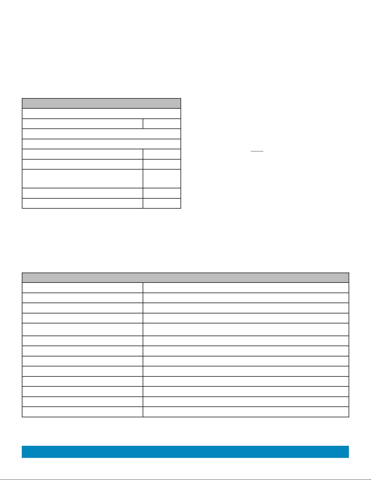
Please refer to the example below:
Duct Run Calculation:
Recommended maximum run
8” round duct 50 ft
Duct piece deduction
Each 90º elbow used 9 ft
Each 45º elbow used 5 ft
Each round to rectangle transition
used
7 ft
Side wall cap with damper 7 ft
Roof cap 7 ft
Duct Run Calcuation example:
One roof cap, two 90º elbows, and one 45º elbow
used:
7ft + 9ft + 9ft + 5ft = 30ft used.
The above duct pieces used are equivalent to 30ft
of a straight duct run. Subtract 30ft from the al-
lowable 50ft. The remaining distance of 20ft is the
longest that the straight ducting (in addition to the
vent pieces) can be.
Body Seamless Stainless Steel, Brushed Finish
Power Rating
General Input Power
220V/50Hz
Motor Input Power 240W (120W +120W)
Motor Revolution 800 RPM (±10%) to 1300 RPM (±10%)
Levels Of Speed Control 4 Levels
Maximum Airow 1000 CFM
Noise Level (Q/L/M/H) 1.5 Sone(46dB) / 3.5 Sone(58dB) / 5.3 Sone(64dB) / 7.5 Sone (69dB)
Motor Type Double Motor
Control Type Touch Control
Filtration Type Stainless Steel Bae Filters
Illumination 3W LED
Venting Size Top, 8 inches Round
* Subject to change without notice, please contact
Infernus
Range Hoods for details.
CALCULATING DUCT SYSTEM LENGTH
SPECIFICATIONS*
Infernus range hoods
240W + # of Light x 3W

VICTORY range hoods
6| AP238-PS15 VERONA / ELITE | 9
Putty
Knife Pencil
Tape
Measure
Level
Phillips
Screwdriver
Aluminum Tape
Power
Drill
Utility
Knife Drywall
Knife
NOTE:
Flat Screw
6pcs
Where necessary, additional screws will be needed for installation and added support, but
REQUIRED TOOLS
PARTS SUPPLIED
Self-Drilling Plastic
Drywall Anchor
Anchor Screw
6pcs
6pcs
is not included. Please review contents before installation.
Hood-mounting
bracket
Filters
Filters spacer
Grease tunnel
Infernus range hoods
VICTORY range hoods
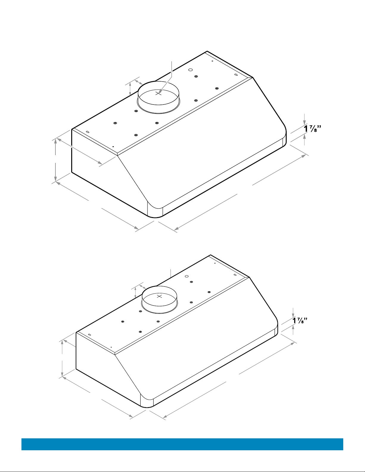
41½”
22”
9¾”
12”
2”
1”
| VERONA / ELITE
10
AP238-PS15 | 7
35½”
22”
9¾”
12”
2”
1”
DIMENSIONS
8”- Ø
AP238-PS15-36
(Continued)
AP238-PS15-42
8”- Ø
Infernus range hoods

22”
59½”
9¾”
12”
2”
1”
VICTORY range hoods
8 | AP238-PS15 VERONA / ELITE | 13
47½”
22”
9¾”
12”
2”
1”
DIMENSIONS
8”- Ø
AP238-PS15-48
(Continued)
AP238-PS15-60
8”- Ø
Infernus range hoods

VICTORY range hoods
| VERONA / ELITE
14 AP238-PS15 | 9
BEFORE INSTALLING THE RANGE HOOD, CHECK FOR PHYSICAL DAMAGES.
THIS RANGE HOODS COMES WITH A WIRE AND PLUG.
TEST THE HOOD BEFORE INSTALLATION.
If there is a grinding noise coming from the motor, DO NOT INSTALL IT, contact us as soon as possible.
Advanced Preparations:
1. Read the entire installation guide and users manual thoroughly, understand instructions and warnings.
2. Be familiar with the controls of the range hood.
3. Place the range hood on a at, stable surface. Connect the range hood to a designated standard outlet
(please refer the product label for the suitable voltage of this unit) and verify no debris has entered the
duct openings, then turn on the range hood.
4. Place all supplied parts and required hardware on a at, stable surface and verify the existence of all
supplied parts.
5. Carefully remove the white/blue plastic protective coat from the chimney covers and range hood if any.
Preparations:
NOTE: To avoid damage to your hood, preduct debris from entering the duct opening.
1. Determine and mark the center line on the ceiling where the range hood will be installed. Make sure
there is proper clearance within the ceiling or wall for exhaust duct.
2. Due to the weight and size of this unit, please make sure that the support system or framework being
used is stable and secure in the ceiling.
3. Put a thick, protective covering over counter top, cook top or range to protect from damage or dirt.
Remove any hazardous objects around the area when installing.
4. Mark the locations of the support mounting bracket holes, vent cutout (if used) and power supply cable
cutout on the ceiling. Use drill and saber saw or keyhole saw to cut openings for power supply cable and
duct.
5. Use caulking to seal exterior wall or roof openings.
6. Disconnect main electrical supply, prepare and run electrical wiring through ceiling. Leave approximately
12” of electrical cord hanging from the ceiling. Do not restore power until wiring is completed.
7. Disconnect power cord, remove the stainless steel bae lter and grease tunnel.
8. Set aside the stainless steel bae lters and grease tunnel until the range hood is properly installed.
PREPARATION
Infernus range hoods

VICTORY range hoods
10 | AP238-PS15 VERONA / ELITE | 23
Centerline
Max: 30”
Min: 24”
30”, 36”, 42”, 48”
*Verona / **Elite
120v Outlet
location
Side Cabinet
Side Cabinet
Cooking Surface
Ceiling
FRONT VIEW
Back Wall
TOP VIEW
Bottom panel of the top cabinet
Top view of range hood
***Cut separate openings underneathe
the cabinet to accommodate the
size of the connector and hard-wiring
Back Wall
TOP VIEW
Drill pilot holes underneathe
the cabinet that line up with
the installation holes on top
panel of range hood
Bottom panel of the top cabinet
Top view of range hood
NOTE: To install directly under the cabinet, there is
no need to install the Mounting Bracket at the back
of the range hood.
(2) Measure the distance between the stove top and
the bottom of range hood. A distance of 24” to 30” is
recommended*.
*Due to dierent ceiling height congurations,
recommended height may not be applicable.
Wall or roof vent may be installed in these areas
but not recommended.
Preferred areas to install wall or roof vent
ducting.
INSTALLATION
Infernus range hoods
VICTORY range hoods
| VERONA / ELITE
22 AP238-PS15 | 11
Centerline
Ceiling
Cabinet
Wall
Centerline
Ceiling
Wall
Cabinet
bottom panel of the existing wall-mounted cabinet.
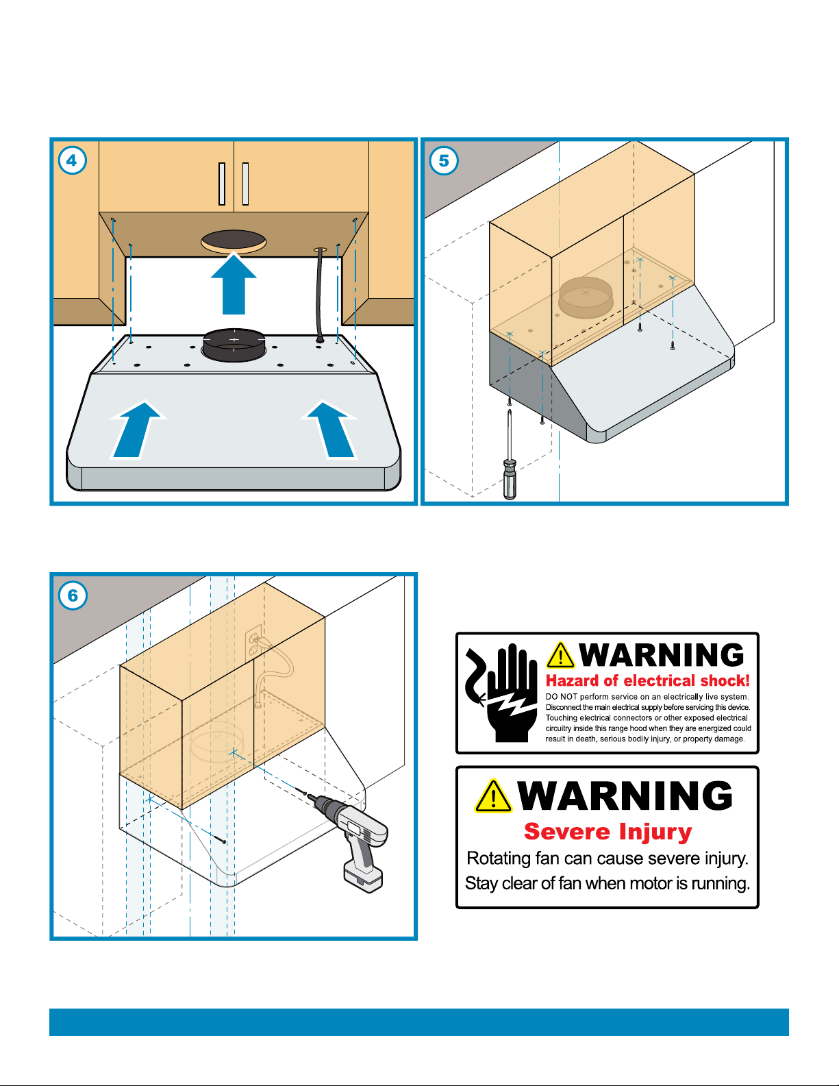
(6) From the inside rear panel of the range hood, use woodscrews (not included) to mount into the studs based on your
measurements already established in the pre-drill. Connect the range hood’s electrical wiring and check the fan motor and
lights are functioning. Be alert of any electrical hazards and refer to the product label for the suitable voltage of this unit.
(1) Lift and insert the range hood underneathe (5) Screw in woodscrews (not included) from inside
the cabinet. Ensure the wiring passes through the the top panel of the range hood mounting to the
opening created below the cabinet.
CAUTION: Make certain the range hood
is secure before releasing!
INSTALLATION (continued)
Infernus range hoods

VICTORY range hoods
12 | AP238-PS15 VERONA / ELITE | 25
8”- Ø Elbow Duct
8”- Ø Connector
Cut out hole
in wall to
accommodate
elbow duct.
Distance from
wall to connector
circumference
edge: 1”
WALL VENT
Counter
Top
Ceiling
Wall
Cabinets
8”- Ø
Elbow Duct
inserted into
wall cut out
8”- Ø
Elbow Duct
inserted into
wall cut out
Use aluminum
foil tape to make
all joints secure
and air tight
Distance from
wall to transition
circumference
edge: 1”
Centerline
8”- Ø Duct
8”- Ø Transition
Cut out hole
on the top panel
of cabinet, and
in ceiling for
exhaust duct
ROOF VENT
Counter
Top
Ceiling
Wall
Cabinets
*Distance from wall to transition circumference edge for 8” - Ø Transition will be 1”. Use aluminum foil tape to make all
joints secure and air tight.
Use 8” round steel pipe to connect the exhaust on the
hood to the ductwork above. Use aluminum foil tape to
make all joints secure and air tight.
Ensure the cylinder duct passes through, leading to
the roof cut out for exhaust connecting duct.
INSTALLATION (continued)
Infernus range hoods
VICTORY range hoods
| VERONA / ELITE
24 AP238-PS15 | 13
SIDE VIEW
BOTTOM
VIEW
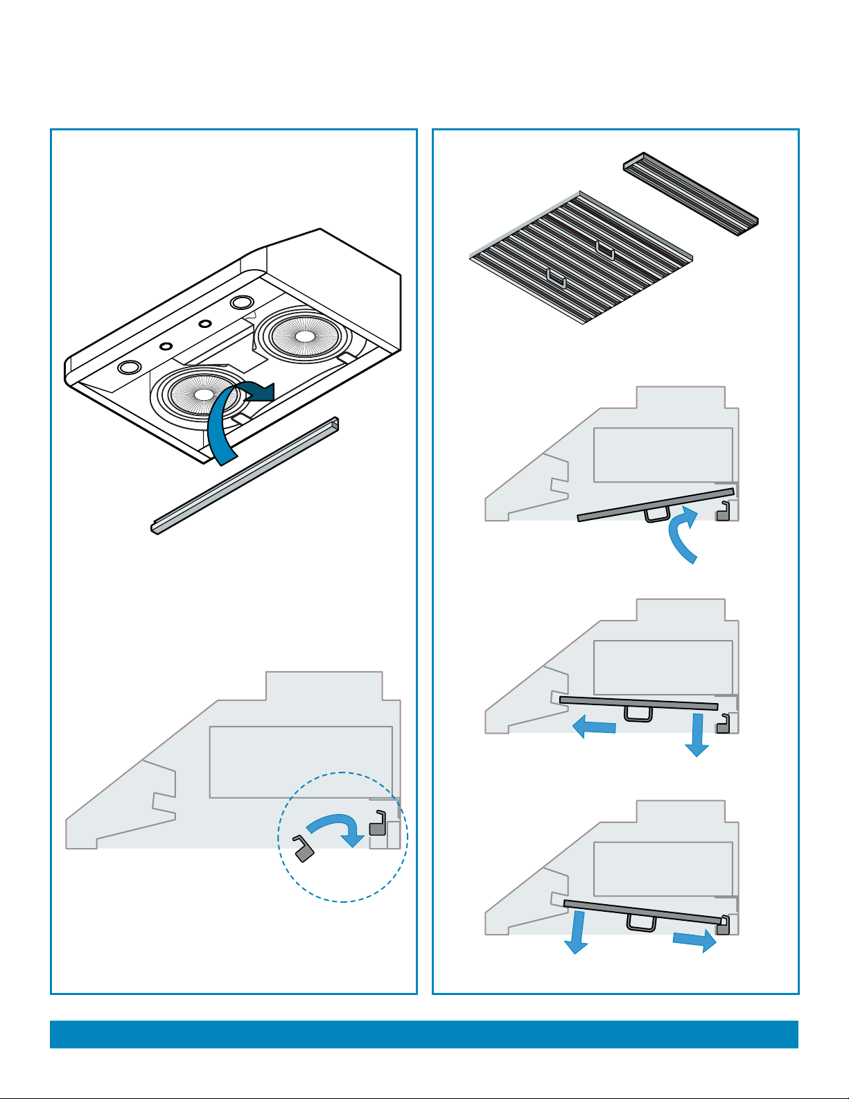
Grease Tunnel
Place Grease Tunnel into the hood opening and insert
into slot holding, as shown below.
Bae Filter
Filter spacer
will vary in size
and amount
depending on
model.
Angle lter toward rear of hood opening above the grease
tunnel.
Slide forward and into the recess towards front of hood and
above the light panel.
Lower lter while sliding back until it rests onto Grease Tunnel.
GREASE TUNNEL & FILTERS
Infernus range hoods

VICTORY range hoods
14 | AP238-PS15 VERONA / ELITE | 27
Optional Backdraft Damper
Wrap insulation required
for cold climates
8” Ø
Duct
36”
typical
Min: 24” Max: 30”
11¾”
*Min height: 74 ¾”
from bottom of duct
to ground when range
height to stove is 24”
Min height: 80 ¾”
from bottom of duct
to ground when range
height to stove is 30”
Wall Vent
Roof Vent
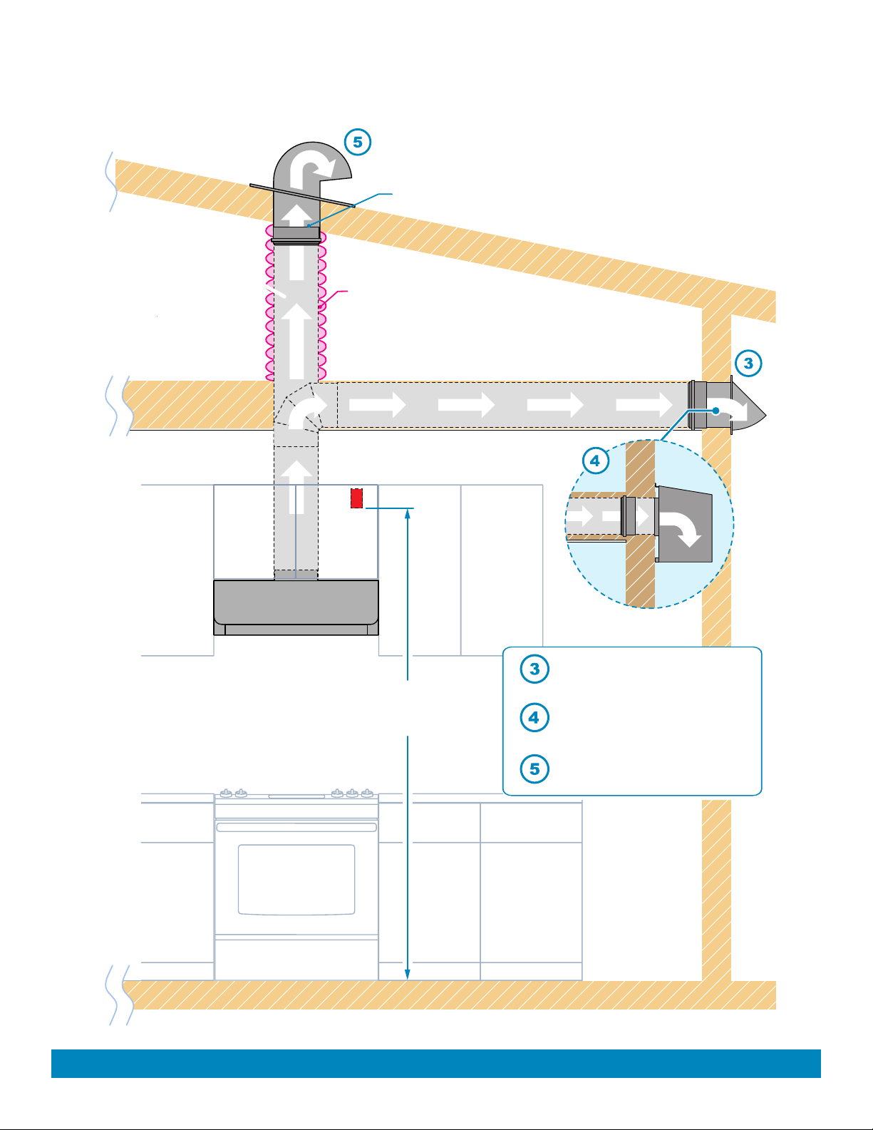
• This range hood is factory set for venting through the roof or wall.
• Duct work can terminate either through the roof or wall. To vent through a wall,
a 90° elbow is needed.
• NEVER exhaust air or terminate
duct work into spaces between
walls, crawl spaces, ceiling,
attics or garages. All exhaust
must be vented to the outside.
• Use metal/aluminum duct work
only.
• Fasten all connections with
sheet metal screws and tape all
joints with certied Aluminum
Tape.
• Use caulking to seal exterior
wall or roof opening around the
cap.
• Colder climates require wrap-
ping insulation around the ducts
and optional blowers.
• The system must have a
Backdraft Damper.
* Due to dierent ceiling height congurations, recommended height may not be applicable.
VENTING METHODS (side view)
Infernus range hoods
VICTORY range hoods
| VERONA / ELITE
26 AP238-PS15 | 15
Backdraft Damper
Wrap insulation
required for cold climates
8” Ø Duct remote
blower installations
Power Outlet
Min: 85”
from floor
Wall Vent Cap
Optional Outdoor
Remote Blower
Roof Vent
VENTING METHODS
* Due to dierent ceiling height congurations, recommended height may not be applicable.
(front view)
Infernus range hoods

VICTORY range hoods
16 | AP238-PS15 VERONA / ELITE | 29
WIRING DIAGRAM
Infernus range hoods
Brown

VICTORY range hoods VERONA / ELITE | 29
RANGE HOOD OPERATIONS
In addition to the remote control feature, this range hood is also equipped with a heat sensor that
will self-calibrate in 5 seconds when the range hood is first electrically activated when selfcalibra-
tion is done. To con-serve energy, the LCD panel will turn off automatically after 5 seconds of
inactivity. For the best results, start the range hood before cooking and allow it to operate several
minutes after the cooking is completed to clear all smoke and odors from the kitchen.
·While the range hood is on and the blower is running, press Decrease button to decrease
blower speed (“F4”to “F1”) as indicated in LCD panel. The Decrease button cycle blower
settings from “high”speed (F4), to “medium”speed (F3), “low”speed (F2), “quiet”
speed (F1) to “off”
•While the range hood is off, use the Increase or Decrease buttons to start the blower.
Press Increase button to increase blower speed (“F1” to “F4”) as indicated in LCD panel.
The Increase button cycles blower settings from “off” (00), “quiet” speed (F1), “low” speed
Activating Ventilation Function:
(F2), “medium” speed (F3) to “high” speed (F4).
(00).
Adjusting Heat Sensitive Auto Speed (HSAS) Function:
AP238-PS15 |
·While the range hood is off and Auto Function is activated, the blower will turn on to its highest
speed automatically when the internal temperature is 4 times above the evel settings temperature.
It will then adjust the speed level (between F4 to F1) automatically according to the detected
temperature between the sensors (4 times to 1 time). The automatic speed level can be manually
overwritten by pressing the Increase or Decrease button and then Auto Function will reactivate
after 2 minutes. The blower can ONLY be turned off MANUALLY or by activating the Power-Off
·While the range hood is off, press and hold Auto Function button to enter the temperature setting
mode. Use the Increase or Decrease button to adjust the comparison temperature value between
the internal and external heat sensors from “8°F”to“20°F”(these values are not exact
measurements but are level settings). The temperature setting mode will exit automatically after
5 seconds of inactivity.
Delay Timer Function.
17
Infernus range hoods

VICTORY range hoods
18 | AP238-PS15 VERONA / ELITE | 29
RANGE HOOD OPERATIONS
Activating Light Function:
• Press Light button once to turn on the lights, and once again to turn off the lights.
CAUTION:
DO NOT touch the lights or surrounding surface until turned OFF and allowed to cool
Activating Power-Off Delay Function:
·While the range hood is on and the blower is running, press Power-Off Delay button to activate
delay off timer and “Timer Shutoff” icon will appear in LCD panel. Adjust to desired period of
delay off timer by pressing Increase or Decrease button (minimum 1 minute to maximum 15
minutes). Timer begins to countdown immediately, when it reaches 0, the blower will shut off.
Adjusting Clock Function:
• While the range hood is off, press Power-off Delay button once to enter the clock setting mode;
use the Increase or Decrease button to set the Hours column; press the Power-off Delay button
again to set the Minutes column; press the Power-off Delay button again to exit the clock setting
mode.
Remote Control Sensor:
• Remote control sensor receives infrared (“IR”) signal from the remote control. The maximum
distance for IR data transmission is about 3 meter (10 ft.) and requires direct line of sight. The
transmission distance may vary depending on temperature and remote control battery condition.
Infernus range hoods

VICTORY range hoods
| VERONA / ELITE
28 AP238-PS15 | 19
1. If the range hood or lights do not operate after
installation:
• Check if the range hood has been plugged in,
make sure that all power has been turned back
ON, fused not blown and all electrical wiring are
properly connected.
• Swap out light assembly to working ones to
determine whether it is caused by defective bulbs.
See Replacing the light bulbs page.
2. The range hood vibrates when the blower is on: • The range hood might not have been secured
properly on to the ceiling or wall.
• The impeller may be out of balance.
3. The blower or fan seems weak: • Duct is too small. Range hood WILL NOT function
eciently with insucient duct size. For example:
Connecting this hood to 4”, 5” or 6” duct will reduce
the suction and create extra noise and vibrations.
Check if duct is clogged or if damper unit is not
installed correctly or opening properly. A tight mesh
on a side wall cap unit might also cause restriction
to the air ow.
4. The lights work but the blower is not spinning at all,
is stuck or is rattling.
• The blower might be jammed or scraping the
bottom due to shipping damage. Please contact us
immediately.
5. The hood is not venting out properly: • Make sure the distance between the stove top
and the bottom of the hood is within* 24” and
30” in distance. *Due to dierent ceiling height
congurations, recommended height may not be
applicable.
• Reduce the number of elbows and length of duct
work. Check if all joints are properly connected,
sealed, and taped.
• Make sure the power is on high speed for heavy
cooking.
• The duct size must be 8”, or larger. Please make
sure there are NO reducers or plenums in the duct
work.
NOTE: For all other inquiries, please contact
Infernus
Range Hoods.
TROUBLESHOOTING
Infernus range hoods

VICTORY range hoods
20 | AP238-PS15 VERONA / ELITE | 31
(a)
(b)
(c)
a. Avoid the use of sharp elbows. Use 45 degrees instead, if possible.
b. DO NOT use REDUCERS. Keep the size of the duct the same, as per the manual. A reducer will
reduce the CFM of the hood and increase the noise.
c. DO NOT use plenum boxes. Boxes create turbulence and make the hood inecient. Use a smooth
elbow to guide the air outdoors.
DO’S AND DON’TS FOR DUCT VENTING
BULB REPLACEMENT
Replacing the 3W 12V LED Light Bulb :
1. Should the light bulb burned out due to age and prolonged use, replace with following: LED 3W 12V
2. Make sure the range hood is unplugged or turn OFF breaker and the lights are cool to touch.
3. Place a flat-head screwdriver between light housing and hood body, gently pry up the light housing and
search for the metal clip.
4. Apply force to the metal clip and pull out the light fixture. Disconnect the power cable and discard the old
light fixture.
5. Reverse the steps to install a new light finture. Turn ON breaker and range hood to test for operation.
Infernus range hoods
Metal Clip Power plug
Table of contents


