XMC4700/XMC4800 Relax Kit Series-V1
Table of Contents
Board Users Manual 4 Revision 1.2, 2016-06-16
Table of Contents
1 Introduction ........................................................................................................................................5
1.1 Key Features........................................................................................................................................6
1.2 Block Diagram......................................................................................................................................7
2 Hardware Description........................................................................................................................7
2.1 Power Supply.....................................................................................................................................10
2.2 Pin Header X1 and X2 .......................................................................................................................11
2.3 Arduino Compatible Connector..........................................................................................................12
2.4 User Push Buttons and User LEDs....................................................................................................13
2.5 Debugging and UART-to-USB Communiction...................................................................................13
2.5.1 On-board Debug Probe......................................................................................................................13
2.5.2 Cortex™Debug Connector (10-pin) ..................................................................................................13
2.6 Reset..................................................................................................................................................14
2.7 CAN Transceiver................................................................................................................................14
2.8 Serial Flash Memory ..........................................................................................................................14
2.9 microSD Card.....................................................................................................................................15
2.10 Ethernet..............................................................................................................................................15
2.11 Boot Option ........................................................................................................................................15
3 Production Data................................................................................................................................16
3.1 Schematics.........................................................................................................................................16
3.2 Components Placement and Geometry.............................................................................................22
3.3 List of Material....................................................................................................................................23
List of Figures
Figure 1 Block Diagram of the XMC4700/XMC4800 Relax Kit Series-V1 .........................................................7
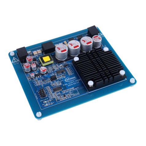
Figure 2 XMC4700 Relax Lite Kit.......................................................................................................................8
Figure 3 XMC4700 Relax Kit for 5V Shields ......................................................................................................8
Figure 4 XMC4700 Relax Kit..............................................................................................................................9
Figure 5 The XMC4800 Relax EtherCAT Kit includes the XMC EtherCAT PHY Board ....................................9
Figure 6 Power Supply Concept.......................................................................................................................10
Figure 7 Signal mapping of the pin headers X1 and X2...................................................................................11
Figure 8 Mapping of Arduino Functions to XMC Pin Functions .......................................................................12
Figure 9 Relax Kit Schematic: MCU, Push Buttons, LEDs, Reset Button, Crystals, USB...............................17
Figure 10 Relax Kit Schematic: OBD Probe, Ethernet, Quad-SPI Memory, microSD Card Slot.......................18
Figure 11 Relax Kit Schematic: Pin Header, Voltage Level Shifter, Power Supply, CAN transceiver...............19
Figure 12 XMC EtherCAT Phy Board Schematic: Input and Output Phy ..........................................................20
Figure 13 XMC EtherCAT Phy Board Schematic: Power, Connectors, LEDs...................................................21
Figure 14 Components Placement and Geometry.............................................................................................22
List of Tables
Table 1 Kit Specification....................................................................................................................................5
Table 2 Kit Features of Assembly Versions......................................................................................................6
Table 3 XMC4700/XMC4800 Pin Mapping for User LEDs .............................................................................13
Table 4 XMC4700/XMC4800 Pin Mapping for User Push Buttons.................................................................13
Table 5 XMC4700/XMC4800 Pins Mapping for Debugging and UART-Communication ...............................13
Table 6 Pin Assignment of the Cortex™Debug Connector (X102)................................................................13
Table 7 CAN Signals and XMC4700/XMC4800 Pin Mapping.........................................................................14
Table 8 XMC4700/XMC4800 Pins Mapping for Serial Flash Memory............................................................14
Table 9 XMC4700/XMC4800 Pins Mapping for microSD Card ......................................................................15
Table 10 XMC4700/XMC4800 Pins used for Ethernet .....................................................................................15
Table 11 Boot Mode Selection with external Pull Resistors..............................................................................15
Table 12 List of Material....................................................................................................................................23


