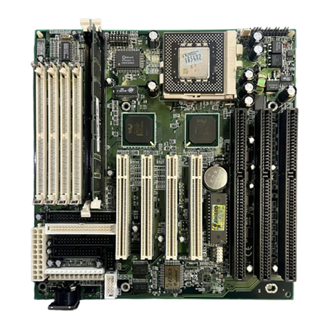
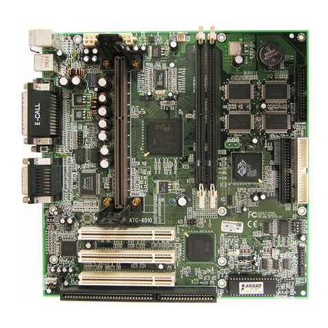
A-Trend ATC-6120 User manual

1
TableofContents
COMPONENTLOCATIONDIAGRAM................................A
INDEX........................................................................................1
CHAPTER1Introduction...................................................2
1-1SystemFeatures...........................................................................3
1-2Soft-OFF-Control.........................................................................4
1-3LDCM(LANDeskClientManager,option)................................5
1-4SMM LEDOperation(option).....................................................6
1-5Thermister(option)......................................................................7
1-6Wake-On-LAN............................................................................7
1-7CheckListofthePackaging.........................................................8
CHAPTER2Installation.....................................................9
2-1InstallationProcedure.................................................................9
2-2CPUInstallation..........................................................................10
2-3SystemMemoryInstallation.........................................................16
2-4ConnectorsDescription................................................................17
2-5IDEDriverInstallation.................................................................22
CHAPTER3AwardBIOSSetup........................................23
3-1UpdateBIOSProcedure..............................................................24
3-2AwardSystemBIOSConfigurationSetup....................................26
AppendixA................................................................................ 56

2
CHAPTER1INTRODUCTION
ThismanualdescribeshowtoconfiguretheATC-6120 mainboardfordifferent
environments.It'sanoverviewofthelayoutandfeaturesofthemainboard,andalso
providesinformationforyoutochangetheconfigurationorsystemenvironment.
ThismanualisdividedintoThree parts:
PARTONEincludespageAandtwochaptersasfollowing:
PageAcontainslayoutdiagramofthemainboard.Pleaserefertoit
whenyouconfigurethesystem.
Chapter1isanoverviewofthemainboardfeaturesandpacking contents.
Chapter2describeshowtoupgradeandtochangehardwareconfigurations
suchasmemorysize,CPUtype,andlistsofjumpersettingsand
connectors.
PARTTWOincludeschapter3whichcontainsAwardBIOSdescription..
Chapter3istheuser'sguideoftheAwardBIOSsetuputilityandFlashROMBIOS.
Themenu showninthischapterarethedefaultsettings.
PARTTHREE includesAPPENDIXAandAPPENDIXB,
APPENDIXAisatechnicalsupportform
Yoursystemdealerwill setupthemainboardaccording toyourdemandofthecomputer.I
meansthatthecurrentsettingsofyourmainboardmaynotbethesameasthedefaultsshowni
n
thisuser'smanual.Ifyouneedtochangeyourconfiguration,pleaseaskyourdealerfirst.Besur
e
thiswill notvoidyoursystemwarranty,oraskyourdealertodo itforyou.
REMARK
Intel®isaregisteredtrademarkofIntelCorporation.
All otherbrandsandproductnamesaretrademarksregisteredtrademarksoftheirrespectivecompanies.

3
1-1SYSTEMFEATURES
:INTELPentiumII CPUoperating at233MHzand333MHzbyusing SingleEdge
Contact(S.E.C.)cartridge(ornamedSlot1).
:INTEL82440LXPCIset.
:Using three 168-pinDIMM sockets,providesthree banksof64-bitwidepathupto
384MBSDRAMor768MBEDO DRAM(withparitychipECC support).
:Built-inSwitching VoltageRegulator.
:INTELLDCMsoftware.(option)
:Supportsauto-detectCPUcorevoltagerange1.8Vto3.5V.
:SupportsoneAGPslot,fourPCIrevision2.1interface compliantandthree 16-bitISA
slots.
:DualMasterIDEconnectorssupportUltraDMA/33,uptofourdevicesintwochannels
forconnecting ofhigh capacityharddrive,CD-ROM,tapebackupetc..
:SupportstheUSB(UniversalSerialBus)connector.
:PS/2keyboardconnectorandPS/2mouseconnector.
:Winbond83977 high-speedUltraMulti-I/Ochipset.
:SupportsInfraredtransfer(IrDATX/RX)connection.
:OneFDCportsupportstwodevicesupto2.88MB
:Two16550AfastUARTscompatibleserialports
:OneEPP/ECPmodeparallelport
:HardwareDimensionis190mm x305mm (7.48"x12.00").

4
1-2SOFTWAREPOWEROFF CONTROL
Themainboarddesign supportsSoftwarePowerOff Controlfeaturethrough theSMM
codeintheBIOSunderWindows95,Windows3.1x,andMS-DOSoperationsystem
environment.ThisisIntelATXformfactorfeatureandyoushoulduseATXpowersupply.
First,youshouldconnectthepowerswitchcable(providedbytheATXcasesupplier)
totheconnector“PS-ON”(nexttoSW1)onthemainboard.IntheBIOSscreenof
‘POWERMANAGEMENTSETUP’,choose“UserDefined”(or“Min.PowerSaving”or
“Max.PowerSaving”)in‘PowerManager’andchoose“Yes”in‘PMControlbyAPM’.
InWindows95,ifyouwouldliketopoweroff thesystem,youjustchoose“shutdown
thecomputer?”inthe“ShutDownWindows“fromWindows95,thenthesystempower
will beoff directly,andbecomethestand-bystatus.Youwill findthepowerLEDlight
blinking.Ifyouwouldliketorestartthesystem,justpress thepowerswitchbutton,andthe
systemwill bepoweredon.
InWindows3.1xorMS-DOS,youshouldcopytheprogramof“down.com”(youcan
finditinthedisketteoftheIDEdriver) intotheharddrive.Whenyouwouldliketopower
off thesystem,justrun this“down.com”,thenthesystemwill beshutdownandstayin
standbystatus.
Note:Ifyouwill leaveyoursystemforseveraldays,wesuggestyouusehardwarepower
off toshutdownyoursystem.

5
1-3LDCM
¡]
LANDeskClientManager
¡^
(option)
ATC-6120 built-incontrollersupportIntelLDCM.LDCMcansatisfyuserswhowant
manageablesystemsthatcaninteractautomaticallywiththeuser.Clientmanageristhe
answer,enabling bothadministratorsandclientstomanagesystems.ThefeaturesofLDCM
areasfollowing :
¡° Reviewsysteminventory
ClientManagerenablesyoutoviewhundredsofinventorieditems.Someoftheseitems
aresoftwarerelated,whilemany othersarehardwarerelated.
¡° ViewDMI-compliantcomponentinformation
Clientmanagerenablesyoutoviewcomponentinformationthatiscompliantwiththe
Desktop ManagerInterface¡]DMI¡^.Thismeansyoucanmanagethird-partyDMI-
compliantcomponentsnotincludedwithClientmanager.
¡° Backup and restore systemconfigurationfiles.
ClientManagerenablesyoubackupandrestoresystemconfigurationfiles.Whenever
youplanonchanging thesystemconfiguration,youcanmakeabackupset.Ifthe
systemnolongerworkscorrectly,afteryouthechangethesystemconfiguration,you
cansimplyrestorethesystemconfigurationwiththebackupset.
¡° Troubleshoot
Since Clientmanagerenablesyoutoviewthesysteminventory,youcaneasily
troubleshootsystemproblems.
¡° Receivenotificationsforsystemevents
Clientmanagerenablesyoutoreceivenotificationofcertainsystemevents.Forexample,
ifthesystemisrunning lowonvirtualmemory,youarenotifiedofthepotentialproblem.
¡° Transfer filestoand fromclientworkstations
Asanadministrator,youhavetheabilitytotransferfilestoandfromclientworkstation.
Thisishelpful,forexample,whenyouneedtoupdateaclientworkstationdriver.
¡° Remotelyrebootclientworkstations
Administratoralsohavetheabilitytoremotelyrebootaworkstation.Thisishelpful
whenyouwantsystemconfigurationchangestotakeeffect.

6
1-4SMM LEDOPERATION(option)
ThemainboardsupportsSMM LEDfunctiontohelpuserstoeasilyrecognizedthe
systemstate,suchasfull on(working),APM(SMM function),Soft-off andmechanism-off
(powercableremove).
YoucanusejumperJP7toswitchoneLEDmodeortwoLEDmode,pleasesee the
following table.
MODE1:TwoLEDmode,JP7set“2-3”
StatePowerLEDSMM LED
Power-onON OFF
Soft-off OFF Flush
Mech-off OFF OFF
APMOFF ON
MODE2:OneLEDmode,JP7set“1-2”
StatePowerLED
Power-onON
Soft-off OFF
Mech-off OFF
APMFlush

7
1-5Thermister (option)
ThismeansthatusercanmonitortheCPUtemperaturethrough thermister.
Whensetting upthethermister,theBioswill loadtheCPUtemperatureautomatically.There
isachoice ofthewarning beepsoundiftheusersettheoptionon.IftheCPUtemperature
overheated,theuserwill getthenotice fromthethermister.Thistimeyou
shouldshutdowncomputerandcheckyourdevices.Oryoucanconnectwithyoudealer.
Therefore,protecting andmonitoring theCPUtemperatureisthethermister’sjob.
1-6Wake-On-LAN
TheremoteWake-On-LANmodeofoperationisamechanismthatusesAdvanced
MicroDevice MagicPackettechnology topowerupasleeping workstationonthenetwork.
ThismechanismisaccomplishedwhentheLANcardreceivesaspecificpacketof
information,calledaMagicPacket,addressedtothenodeonthenetwork.Foradditional
protection,SecureON isanoptionalsecurityfeaturethatcanbeaddedtotheMagicPacket
thatrequiresapasswordtopowerupthesleeping workstation.WhentheLANcardisin
remoteWake-On-LANmode,mainsystempowercanbeshutdownleaving poweronlyfor
theLANcardandauxiliarypowerrecondition.
TheLANcardperformsnonetworkactivitieswhileintheremoteWake-On-LAN
modeofoperation-ItonlymonitorsthenetworkforreceiptofaMagicPacket.IfaMagic
PacketisaddressedtotheLANcardonthenetwork,theLANcardwakeupthesystem.If
theSecureON featurehasbeenenabled,thepasswordaddedtotheMagicPacketisalso
verifiedpriortowaking upthesystem.
YoushouldselecttheLANcardalsosupportWOLfunction.WOLhastwoprotocol.
ThatareINTELandDEC.JP2issettorecongize yourLANcardisINTELorDEC
protocol.(DECprotocolisnotrecommendnow.)
WOLLANcardwill providea3-pinlinetoconnecttheWOLconnectoronthe
mainboard.
WOLJP2
INTEL1-2
DEC2-3

8
1-7CHECKLISTOFTHEPACKAGING
Themainboardcomessecurelypackedinadurableboxandshipping carton.Ifany of
thefollowing itemsaremissing ordamaged,pleasecontactyoursupplier.
Eachmainboardcontains:
Q'TYDescription
1Mainboard:ATC-6120.
1Retentionmodule(forPentiumII installation)
1CD:LDCM,IDEdriver(option)
1Diskette:EnhancedIDEdriver(option)
AwardsystemBIOS
UpdateUtility
1Cable:EnhancedIDEconnector.
1Cable:F.D.D.connector.
1Manual:User`smanual.
NOTE :Leavethemainboardinitsoriginalpackaging until youarereadytoinstall it.

9
CHAPTER2INSTALLATION
2-1INSTALLATIONPROCEDURE
Beforeinstalling thecomputer,pleaseprepareall componentssuchasCPU,DRAM;
peripheralssuchasharddrive,keyboard,CD-ROM;andaccessoriessuchascables.Then,
install thesystemasfollowing:
1.Plug CPU/heatsink(refertoPentiumII installationguide),andDRAMmodulesin
themainboard.
2.SetDIPswitchbasedonyourconfiguration.
3.Plug add-oncardsinPCI/ISAslots.
4.Connectcablestoperipherals,powersupply.
5.Makesureall componentsanddevicesarewell connected,turnonthepowerand
setupSystemBIOSbasedonyourconfiguration.
6.Install peripherals,add-oncarddriversandtestthem.
7.Ifall ofaboveproceduresaresuccess,turn-off thepowerthenplug all oftheminto
yourcomputercase.

10
2-2CPUINSTALLATION
ATC-6120 supportsINTELPentiumII CPUcartridge.
2-2-1CPUTYPESELECTION(byBIOS)
1.Press the<Del>keywhenthesystemisbootingup.
2.Thefollowingmainmenu will appear.
ROMPCI/ISABIOS(ATC-6120)
CMOSSETUPUTILITY
AWARDSOFTWARE,INC.
STANDARDCMOSSETUPINTEGRATEDPERIPHERALS
BIOSFEATURESSETUP SUPERVISORPASSWORD
CHIPSET FEATURESSETUPUSERPASSWORD
POWERMANAGEMENTSETUPIDEHDD AUTODETECTION
PNP/PCICONFIGURATION SAVE&EXITSETUP
LOADBIOSDEFAULTSEXITWITHOUTSAVING
LOADSETUPDEFAULTS
ESC:Quitáâàß:SelectItem
F10:Save&ExitSetup (Shift)F2:ChangeColor
ATClock,DRAMTimmings,.......
3.Select“CHIPSET FEATURESSETUP”
STANDARDCMOSSETUPINTEGRATEDPERIPHERALS
BIOSFEATURESSETUP SUPERVISORPASSWORD
CHIPSET FEATURESSETUPUSERPASSWORD
POWERMANAGEMENTSETUPIDEHDD AUTODETECTION
PNP/PCICONFIGURATION SAVE&EXITSETUP
LOADBIOSDEFAULTSEXITWITHOUTSAVING
LOADSETUPDEFAULTS
ESC:Quitáâàß:SelectItem
F10:Save&ExitSetup (Shift)F2:ChangeColor
ATClock,DRAMTimmings,.......

11
4.Thenthefollowingscreenwill appear.
ROMPCI/ISABIOS(ATC-6120)
CHIPSET FEATURESSETUP
AWARDSOFTWARE,INC.
AutoConfiguration:EnabledSDRAMCASlatencyTime:3
DRAMSpeedSelection:60 nsCPUClockRatio:2.0x
MAWaitState:SlowAutoDetectDIMM/PCIClK:Enabled
EDO RAS#ToCAS#Delay:3SpreadSpectrum:Disabled
EDO RAS#PrechargeTime:4CPUClockFrequency:66MHz
EDO DRAMReadBurst:x333
EDO DRAMWriteBurst:x333
DRAMDataIntegrityMode:Non-ECC
CPU-To-PCIIDEPosting:Enabled
SystemBIOSCacheable:Disabled
VideoBIOSCacheable:Disabled
VideoRAMCacheable:Disabled
8BitI/ORecoveryTime:1
16 BitI/ORecoveryTime:1
MemoryHoleAt15M-16M:Disabled
PassiveRelease:EnabledEsc:Quitáâàß:SelectItem
DelayedTransaction:DisabledF1:HelpPU/PD/+/-:Modify
AGPApertureSize (MB):64 F5:OldValues(Shift)F2:Color
SDRAMRAS-to-CASDelay:SlowF6:LoadBIOSDefaults
SDRAMRASPrechargeTime:SlowF7:LoadSetup Defaults
¡°¡° NOTE
IfanincorrectCPUfrequencyissetthroughtheBIOS,asystemfailure may occur.
Thissystemfailure canbesolvedbypressingthe“Insert”keyonthekeyboardtoclearup
theprevioussetfrequency(i.e.backto133MHz(66MHzx2.0)orthedefaultfrequency),
andthenthepower buttontorestartthesystemandresetthevalueinBIOSscreen.Or
user canclearCMOStoresettheBIOSvalue.
AlsoATC-6120 supportskeyboardpower onormousepower onfunction,
(refer to‘IntegratedPeripherals’,page48,49).Whenyouset‘keyboard
power on’,youcanselectsetpasswordornot.Whenyousetpassword,
youshouldkey-inthepasswordtopower onthesystem.Ifyouforgetthe
password,youshouldclearCMOStoresetthesystem.

12
5a.IntelPentiumII 233MHz(66 x3.5)
ROMPCI/ISABIOS(ATC-6120)
CHIPSET FEATURESSETUP
AWARDSOFTWARE,INC.
AutoConfiguration:EnabledSDRAMCASlatencyTime:3
DRAMSpeedSelection:60 nsCPUClockRatio:3.5x
MAWaitState:SlowAutoDetectDIMM/PCIClK:Enabled
EDO RAS#ToCAS#Delay:3SpreadSpectrum:Disabled
EDO RAS#PrechargeTime:3CPUClockFrequency:66MHz
EDO DRAMReadBurst(B/E/F):x333
EDO DRAMWriteBurst(B/E/F):x222
DRAMDataIntegrityMode:Non-ECC
CPU-to-PCIIDEPosting:Enabled
SystemBIOSCacheable:Disabled
VideoBIOSCacheable:Disabled
VideoRAMCacheable:Disabled
8-bitI/ORecoveryTime:1
16-bitI/ORecoveryTime:1
MemoryHoleAt15M-16M:Disabled
PassiveRelease:EnabledEsc:Quitáâàß:SelectItem
DelayedTransaction:EnabledF1:HelpPU/PD/+/-:Modify
AGPApertureSize (MB):64 F5:OldValues(Shift)F2:Color
SDRAMRAS-to-CASDelay:SlowF6:LoadBIOSDefaults
SDRAMRASPrechargeTime:SlowF7:LoadSetup Defaults

13
5b.IntelPentiumII 266MHz(66 x4.0)
ROMPCI/ISABIOS(ATC-6120)
CHIPSET FEATURESSETUP
AWARDSOFTWARE,INC.
AutoConfiguration:EnabledSDRAMCASlatencyTime:3
DRAMSpeedSelection:60 nsCPUClockRatio:4.0x
MAWaitState:SlowAutoDetectDIMM/PCIClK:Enabled
EDO RAS#ToCAS#Delay:3SpreadSpectrum:Disabled
EDO RAS#PrechargeTime:3CPUClockFrequency:66MHz
EDO DRAMReadBurst(B/E/F):x333
EDO DRAMWriteBurst(B/E/F):x222
DRAMDataIntegrityMode:Non-ECC
CPU-to-PCIIDEPosting:Enabled
SystemBIOSCacheable:Disabled
VideoBIOSCacheable:Disabled
VideoRAMCacheable:Disabled
8-bitI/ORecoveryTime:1
16-bitI/ORecoveryTime:1
MemoryHoleAt15M-16M:Disabled
PassiveRelease:EnabledEsc:Quitáâàß:SelectItem
DelayedTransaction:EnabledF1:HelpPU/PD/+/-:Modify
AGPApertureSize (MB):64 F5:OldValues(Shift)F2:Color
SDRAMRAS-to-CASDelay:SlowF6:LoadBIOSDefaults
SDRAMRASPrechargeTime:SlowF7:LoadSetup Defaults

14
5c.IntelPentiumII 300MHz(66 x4.5)
ROMPCI/ISABIOS(ATC-6120)
CHIPSET FEATURESSETUP
AWARDSOFTWARE,INC.
AutoConfiguration:EnabledSDRAMCASlatencyTime:3
DRAMSpeedSelection:60 nsCPUClockRatio:4.5x
MAWaitState:SlowAutoDetectDIMM/PCIClK:Enabled
EDO RAS#ToCAS#Delay:3SpreadSpectrum:Disabled
EDO RAS#PrechargeTime:3CPUClockFrequency:66MHz
EDO DRAMReadBurst(B/E/F):x333
EDO DRAMWriteBurst(B/E/F):x222
DRAMDataIntegrityMode:Non-ECC
CPU-to-PCIIDEPosting:Enabled
SystemBIOSCacheable:Disabled
VideoBIOSCacheable:Disabled
VideoRAMCacheable:Disabled
8-bitI/ORecoveryTime:1
16-bitI/ORecoveryTime:1
MemoryHoleAt15M-16M:Disabled
PassiveRelease:EnabledEsc:Quitáâàß:SelectItem
DelayedTransaction:EnabledF1:HelpPU/PD/+/-:Modify
AGPApertureSize (MB):64 F5:OldValues(Shift)F2:Color
SDRAMRAS-to-CASDelay:SlowF6:LoadBIOSDefaults
SDRAMRASPrechargeTime:SlowF7:LoadSetup Defaults

15
5d.IntelPentiumII 333MHz(66 x5.0)
ROMPCI/ISABIOS(ATC-6120)
CHIPSET FEATURESSETUP
AWARDSOFTWARE,INC.
AutoConfiguration:EnabledSDRAMCASlatencyTime:3
DRAMSpeedSelection:60 nsCPUClockRatio:5.0x
MAWaitState:SlowAutoDetectDIMM/PCIClK:Enabled
EDO RAS#ToCAS#Delay:3SpreadSpectrum:Disabled
EDO RAS#PrechargeTime:3CPUClockFrequency:66MHz
EDO DRAMReadBurst(B/E/F):x333
EDO DRAMWriteBurst(B/E/F):x222
DRAMDataIntegrityMode:Non-ECC
CPU-to-PCIIDEPosting:Enabled
SystemBIOSCacheable:Disabled
VideoBIOSCacheable:Disabled
VideoRAMCacheable:Disabled
8-bitI/ORecoveryTime:1
16-bitI/ORecoveryTime:1
MemoryHoleAt15M-16M:Disabled
PassiveRelease:EnabledEsc:Quitáâàß:SelectItem
DelayedTransaction:EnabledF1:HelpPU/PD/+/-:Modify
AGPApertureSize (MB):64 F5:OldValues(Shift)F2:Color
SDRAMRAS-to-CASDelay:SlowF6:LoadBIOSDefaults
SDRAMRASPrechargeTime:SlowF7:LoadSetup Defaults

16
2-3SYSTEMMEMORY INSTALLATION
TheATC-6120 providesthree 168-pinDIMM socketsforsystemmemoryexpansion
from8MBto384MB.Thesethree DIMMs arearrangedtothree banks,pleasereferto
pageA.Eachbankprovides64-bitwidedatapath.
¡°
SamplesofSystemMemoryCombinationsOptions
¡°
BANK0BANK1BANK2TotalMemory
DIMM 1DIMM 2DIMM 3DIMM 1-3
8MBx1- - 8MB
-8MBx1-8MB
- - 8MBx1 8MB
8MBx1 8MBx1 16MB
-8MBx1 8MBx1 16MB
8MBx1-8MBx1 16MB
16MBx1- - 16MB
-16MBx1-16MB
- - 16MBx1 16MB
8MBx1 8MBx1 8MBx1 24MB
8MBx1 16MBx1-24MB
16MBx1 16MBx1 32MB
16MBx1-16MBx1 32MB
32MBx1- - 32MB
-32MBx1-32MB
- - 32MBx1 32MB
8MBx1 16MBx2 16MBx1 56MB
32MBx1 32MBx1-64MB
-32MBx1 32MBx1 64MB
64MBx1- - 64MB
-64MBx1 64MBx1 128MB
: : : :
128MBx1 128MBx1 128MBx1 384MB

17
2-4CONNECTORSDESCRIPTION
Thelocationsoffollowing connectorsareindicatedinpageA.Whenyouplug acable
intothefollowing I/Oconnectors,youshouldhavethepin1edgeofthecablealign withthe
pin1endoftheconnector.
CONN1:speaker,keyboardlock,reset,SMI,
turbo LED,andIDELEDconnectors.
S
PK
K
E
Y
L
OCK
RST SMI TB-LED IDE-LED
+ +
SPK:speaker
Speaker
GND
GND
VCC
Power LEDconnector
PowerLED+
N/C
GND (power)
Keylock
GND
RST:Resetconnector
ResetSignal
GND
SMI:SMIlead
GND
SMISignal
TB-LED:TurboLEDindicator,LEDon
whensystemrunshigher speed,oras
GND another LEDwhensupportSMM LEDMode
+5V(nexttoCPU)
PSON

18
FAN :CPUcooling fanconnector.Wirewith
+12Vvoltage(mostlikelyredwire)mustbe
pluggedintopin2,andGROUND wires
(mostlikelyblackwires)mustbepluggedinto
pin3.Pleaseconfirmthewirecolor
re-presentationwithyoursupplier.
CAUTION:Plug wireintowrong connectorwill
DAMAGEfanandmainboard.
FAN1forPentiumII CPUFan,FAN2Chassis,
FAN3forPower card.
IR1:Infraredmoduleconnector.
IDE-LED:IDEdevicesindicatorLED
connector.IDE-LEDstaysON indicates
GND on-boardIDEdevicesinoperation.If
+5Vplug wireintowrong connector,colorof
LEDwill belighterandtheIDEdvicescan
still functionproperly.
1GND
2+12V
3Sense
1+5V
2FIRRX
3IRRX
4GND
5IRTX
CPUFAN
PWRFANChassisFAN

19
PW1 :ATXmode+3.3/5/12Vpowersupplyconnector.
110
11 20
COM1/COM2:thesetwoconnectorsare
usedtoconnectserialportcables.
pinsignalname
1NDCDA/B
2NSINA/B
3NSOUTA/B
4NDTRA/B
5GND
6NDSRA/B
7NRTSA/B
8NCTSA/B
9NRIA/B
AisCOM1,BisCOM2
FDC1:thisconnectorisusedtoconnectthefloppy
drivethrough acable.
pinsignalpinsignal
2RWC-20 STEP-
4reserved 22 WriteData
6FDEDIN24 WriteGate
8Index-26 Track00-
10 MotorEnableA-28 WriteProtect-
12 DriveSele.B-30 ReadData-
14 DriveSele.A-32 Side1Sele.-
16 MotorEnableB-34 DisketteChange
18 DIR-
All ofodd pinsareground
1
6 2
7 3
8 4
9 5
34 33
2 1
1 3.3V6+5V11 3.3V16 GND
2 3.3V7GND 12 -12V17 GND
3GND 8PWRGD13 GND 18 -5V
4+5V9 5VSB 14*PS_ON19 +5V
5GND 10 +12V15 GND 20 +5V
*PS_ON:Soft-Off powercontrol

20
LPT:thisconnectorisusedtoconnectparallel
portcable.
pinsignalpinsignal
1STROBE-10 ACK-
2DataBit0 11 BUSY
3DataBit1 12 PE
4DataBit2 13 SLCT
5DataBit3 14 AutoFeed-
6DataBit4 15 ERROR-
7DataBit5 16 INIT-
8DataBit6 17 SLCTIN-
9DataBit7
pin18 -- pin25 areground
25 13
13 1
PS/2Mous
e
Keyboar
d
conn
.
COM1
COM2
DualUSB
LPT
Table of contents
Other A-Trend Motherboard manuals

A-Trend
A-Trend ATC-6510 User manual

A-Trend
A-Trend ATC-6400 User manual

A-Trend
A-Trend ATC-6320 User manual

A-Trend
A-Trend 6240V User manual

A-Trend
A-Trend 6253M User manual

A-Trend
A-Trend ATC-5030 User manual

A-Trend
A-Trend ATC-6260 User manual

A-Trend
A-Trend ATC-6130E User manual

A-Trend
A-Trend Atc-6240m Mounting instructions

A-Trend
A-Trend ATC-2000 User manual