Infineon TLD7002-16SHIELD User manual
TLD7002-16SHIELD
User guide
Z8F80318869
About this document
Scope and purpose
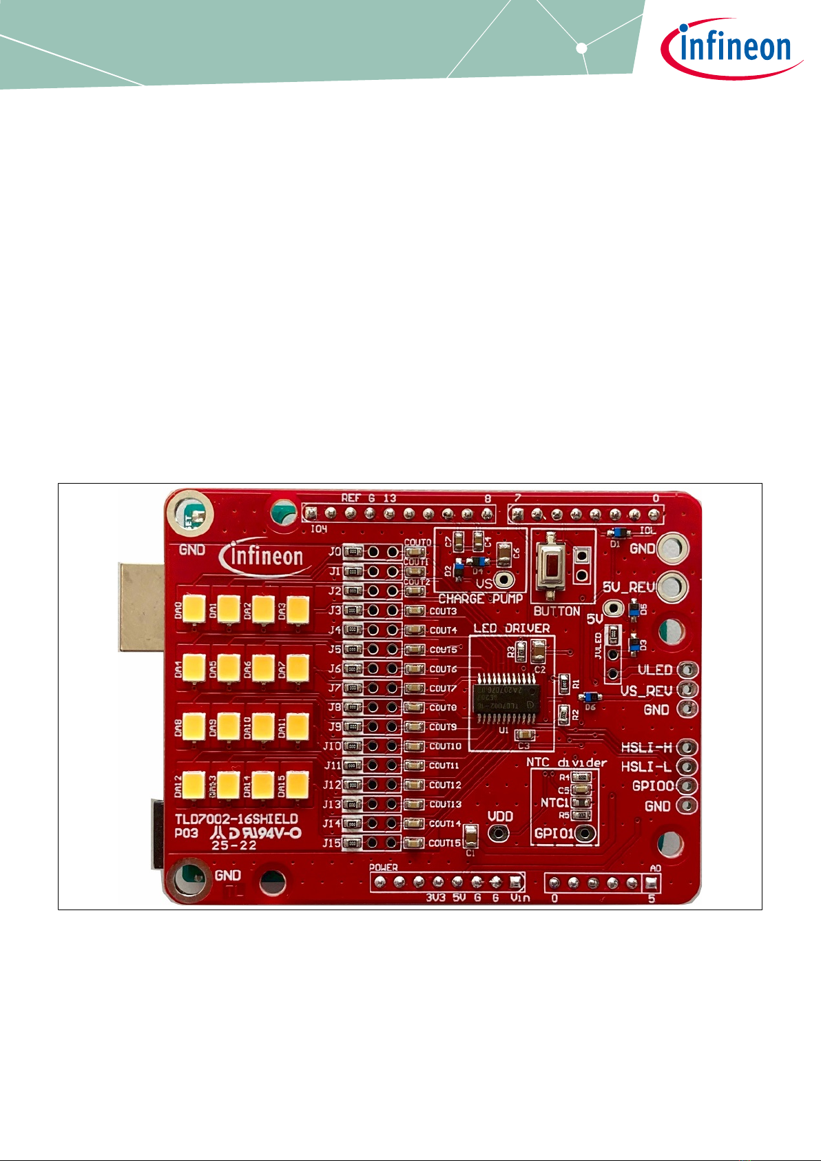
The TLD7002-16SHIELD is an LED driver shield compatible with Arduino UNO. The TLD7002-16ES is a 16
independent-channel-LED driver with individual output current from 5 mA to 76 mA and UART over CAN
interface.
The scope of this user manual is to provide instructions on use of the TLD7002-16SHIELD for a jump-start on the
TLD7002-16ES programming with the simple Arduino IDE.
This user guide describes the TLD7002-16SHIELD with PCB version P03 and P04 in which, only thermal vias are
changed. Additionally, schematic version S03 is described.
This board will be used during design-in, for evaluation and proof of concepts for new projects adopting the
TLD7002-16ES.
Figure 1 TLD7002-16SHIELD
Intended audience
Hardware engineers and soware engineers
User guide Please read the sections "Important notice" and "Warnings" at the end of this document Rev.1.00
www.infineon.com 2022-07-26

Table of contents
About this document . . . . . . . . . . . . . . . . . . . . . . . . . . . . . . . . . . . . . . . . . . . . . . . . . . . . . . . . . . . . . . . . . . . 1
Table of contents . . . . . . . . . . . . . . . . . . . . . . . . . . . . . . . . . . . . . . . . . . . . . . . . . . . . . . . . . . . . . . . . . . . . . . .2
1 Description . . . . . . . . . . . . . . . . . . . . . . . . . . . . . . . . . . . . . . . . . . . . . . . . . . . . . . . . . . . . . . . . . . . . . . . . . . . . 3
1.1 UART over CAN interface connections . . . . . . . . . . . . . . . . . . . . . . . . . . . . . . . . . . . . . . . . . . . . . . . . . . . . . 3
1.2 TLD7002-16ES Power supply options . . . . . . . . . . . . . . . . . . . . . . . . . . . . . . . . . . . . . . . . . . . . . . . . . . . . . . 4
2 Quick start procedure . . . . . . . . . . . . . . . . . . . . . . . . . . . . . . . . . . . . . . . . . . . . . . . . . . . . . . . . . . . . . . . . . . 6
2.1 OTP configuration array and OTP wizard tool . . . . . . . . . . . . . . . . . . . . . . . . . . . . . . . . . . . . . . . . . . . . . . 6
3 Electrical characteristics . . . . . . . . . . . . . . . . . . . . . . . . . . . . . . . . . . . . . . . . . . . . . . . . . . . . . . . . . . . . . . . 8
4 Bill of material . . . . . . . . . . . . . . . . . . . . . . . . . . . . . . . . . . . . . . . . . . . . . . . . . . . . . . . . . . . . . . . . . . . . . . . . . 9
5 PCB layout . . . . . . . . . . . . . . . . . . . . . . . . . . . . . . . . . . . . . . . . . . . . . . . . . . . . . . . . . . . . . . . . . . . . . . . . . . . .10
6 Schematics . . . . . . . . . . . . . . . . . . . . . . . . . . . . . . . . . . . . . . . . . . . . . . . . . . . . . . . . . . . . . . . . . . . . . . . . . . . 11
References . . . . . . . . . . . . . . . . . . . . . . . . . . . . . . . . . . . . . . . . . . . . . . . . . . . . . . . . . . . . . . . . . . . . . . . . . . . .12
Revision history . . . . . . . . . . . . . . . . . . . . . . . . . . . . . . . . . . . . . . . . . . . . . . . . . . . . . . . . . . . . . . . . . . . . . . .13
Disclaimer . . . . . . . . . . . . . . . . . . . . . . . . . . . . . . . . . . . . . . . . . . . . . . . . . . . . . . . . . . . . . . . . . . . . . . . . . . . . 14
TLD7002-16SHIELD
User guide
Table of contents
User guide 2 Rev.1.00
2022-07-26

1 Description
The core of the shields is the TLD7002-16ES which features:
• Output current up to 16 x 76.5 mA
• UART over CAN interface up to 2 Mbit/s compliant with ISO11898-2 (2016) CAN physical layer
• 16 independent 14-bit PWM engines from 100 Hz up to 2 kHz
• Integrated diagnostics for load monitoring and device fault monitor
• ISO26262 compliant development up to ASIL B
The only needed connection from Arduino to drive 16 mid power LEDs is an UART interface and optionally the
TLD7002-16ES GPIN0 pin, which acts as a chip-select during the TLD7002-16ES one time programmable (OTP)
memory programming/emulation.
1.1 UART over CAN interface connections
The TLD7002-16ES has an UART over CAN physical layer interface called HSLI (High Speed Lighting Interface)
which is a dierential BUS. The HSLIL output pin it is an open drain with a diode in series, and it can be
connected directly to a standard UART with a simple workaround without the need for a transceiver. The
resulting logic levels on the RX and TX pins are not CMOS or TTL compliant, and they will have slightly reduced
noise margin compared to standard CMOS gates.
µC
UART TX
UART RX
HSLIH
HSLIL
HSLIH
HSLIL
HSLIH
HSLIL
U1 TLD7002-16ES
CBUS
RTX = 1k
2.5 V
40k typ
40k typ
5V
RUP
RDN
3k3
3k3
2.5V
2.5V 2.5V
U2 TLD7002-16ES
U3 TLD7002-16ES
Figure 2 TLD7002-16ES direct UART connection
Arduino has an internal pull up on the RX pin therefore, instead of the resistor on the TX pin, a diode is placed
on the TX pin. See Figure 3.
TLD7002-16SHIELD
User guide
1 Description
User guide 3 Rev.1.00
2022-07-26
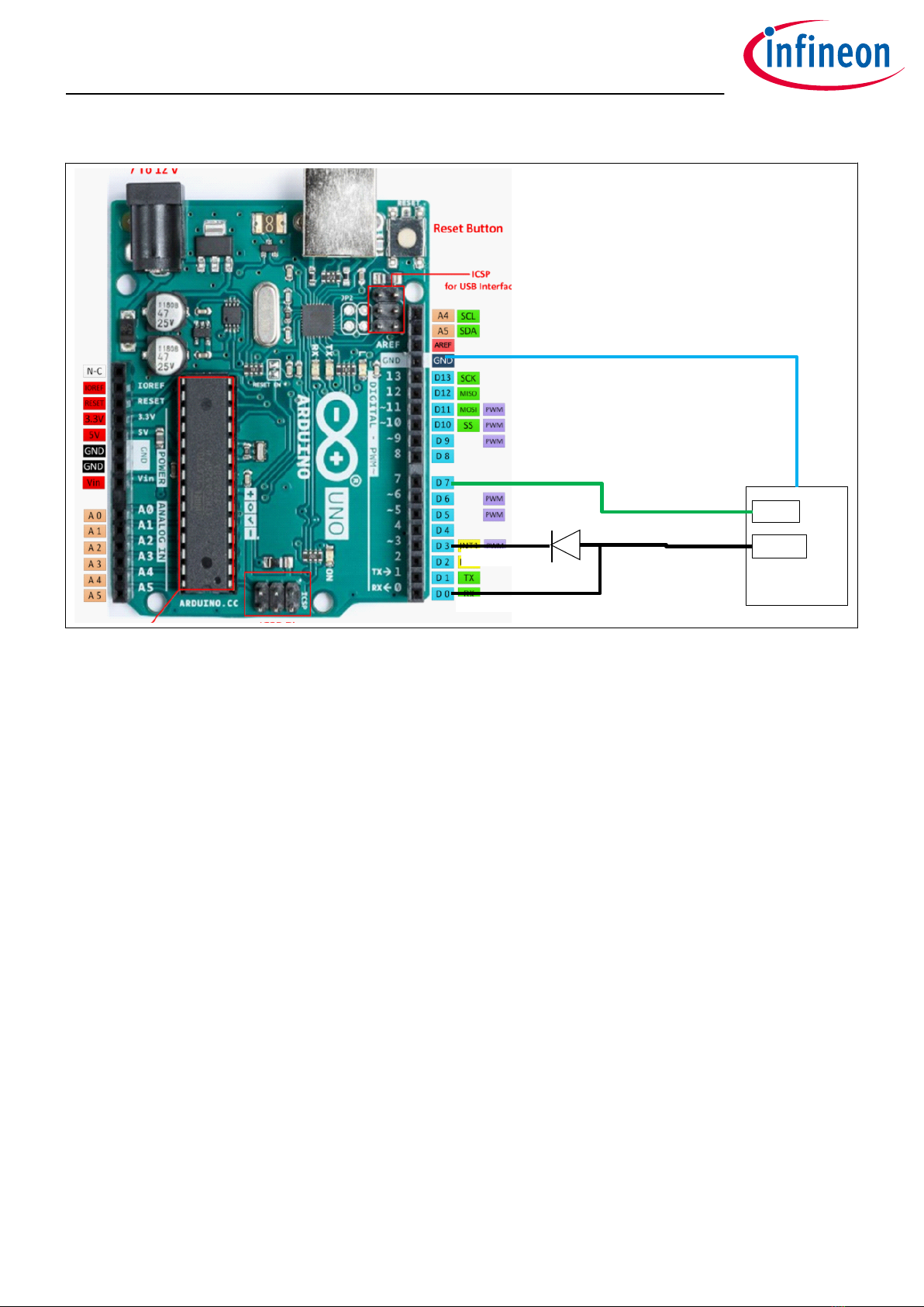
GPIN0
HSLI-L
µC(HW)RX
µC(SW)TX
GND
TLD7002-16
Figure 3 TLD7002-16SHIELD HSLI interface and GPIN0 connections
The TLD7002-16ES UART has a 200 kbps minimum speed. In order to have the serial monitor prints available for
debugging, the TLD7002-16ES has been connected to a so serial port for the Arduino TX, and a hardware serial
port for the Arduino RX signal. UART speed has been set to a standard 230400 bps.
This so/hard serial division is needed because the so serial cannot handle 230 kbps in reception, and
therefore it is not possible to have both so serial for TX and RX connected to TLD7002-16ES UART. The so
serial library has been slightly modified in order to handle the 230 kbps with reduced delay on adjacent bytes.
The Arduino UNO can be programmed even if the TLD7002-16SHIELD is plugged into the Arduino.
1.2 TLD7002-16ES Power supply options
The TLD7002-16ES applications has 2 supply rails:
•VSto power TLD7002-16ES device (VS pin, 6 V to 20 V functional range)
•VLED to power the LEDs
Since its outputs are linear current sources, when possible is better to keep VLED voltage close to the LED load
voltage plus the TLD7002-16ES dropout, to limit the power dissipation on the LED driver. Since the load is only
1 LED per output, the recommended VLED is approximately 4 V, while the VSmust be higher than 6 V.
In order to avoid 2 power supplies connected to the TLD7002-16ES shield, and to supply the board directly by
the Arduino USB, a charge pump has been designed on Arduino pin 9 and 10. The power supply connections are
illustrated below.
TLD7002-16SHIELD
User guide
1 Description
User guide 4 Rev.1.00
2022-07-26
VS
Arduino
5V pin
D9
VS
D9_PWM
D2
NXP_BAT46WJ5V_ARDUINO
D4
NXP_BAT46WJ
GND
C6
4.7uF 25V 0805
D10_PWM
C4
470nF 25V 0603
C7
470nF 25V 0603
D10
Arduino
USB
VS≈9V
charge pump
Arduino sch.
5V USB protection circuit
VLED
Arduino sch.
5V from Vin regulator
JVLED
Jumper
D3
VS_REV
5V_REV
5V_arduino
D5
D6
Figure 4 TLD7002-16SHIELD power supply connections with Arduino UNO R3
The TLD7002-16ES output currents can be as high as 76.5 mA per channel, for a total current of 1224 mA in case
all outputs are on @100% duty. The current setting on the TLD7002-16ES outputs must be adjusted in order to
avoid damages to the Arduino UNO circuitry.
In the provided sketch, the LED current has been set to 20 mA for a total LED current of 320 mA.
The board can be powered in several ways:
• Arduino USB B connector
- Keep total LED current below 400 mA to avoid damages to Arduino T1 transistor, see Figure 4
• Powering the Arduino VIN port with 7 V to keep power on the Arduino LDO (IC2) low
- Keep total LED current below 400 mA
• Providing external 5 V to the Arduino 5V_REV test point with an external power supply
- Keep total LED current below 800 mA to avoid damages to D5 and D3
- Do not exceed 5.5 V or the the Arduino UNO board will be damaged
• Powering the Arduino with one power supply (Either at VIN or USB) while VLED is powered by an external
power supply (4 V to 6 V is recommended). Remove JVLED Jumper for this option
- Total LED current can go up to 1224 mA
TLD7002-16SHIELD
User guide
1 Description
User guide 5 Rev.1.00
2022-07-26
2 Quick start procedure
A step-by-step procedure is laid out for setting up and running the shield.
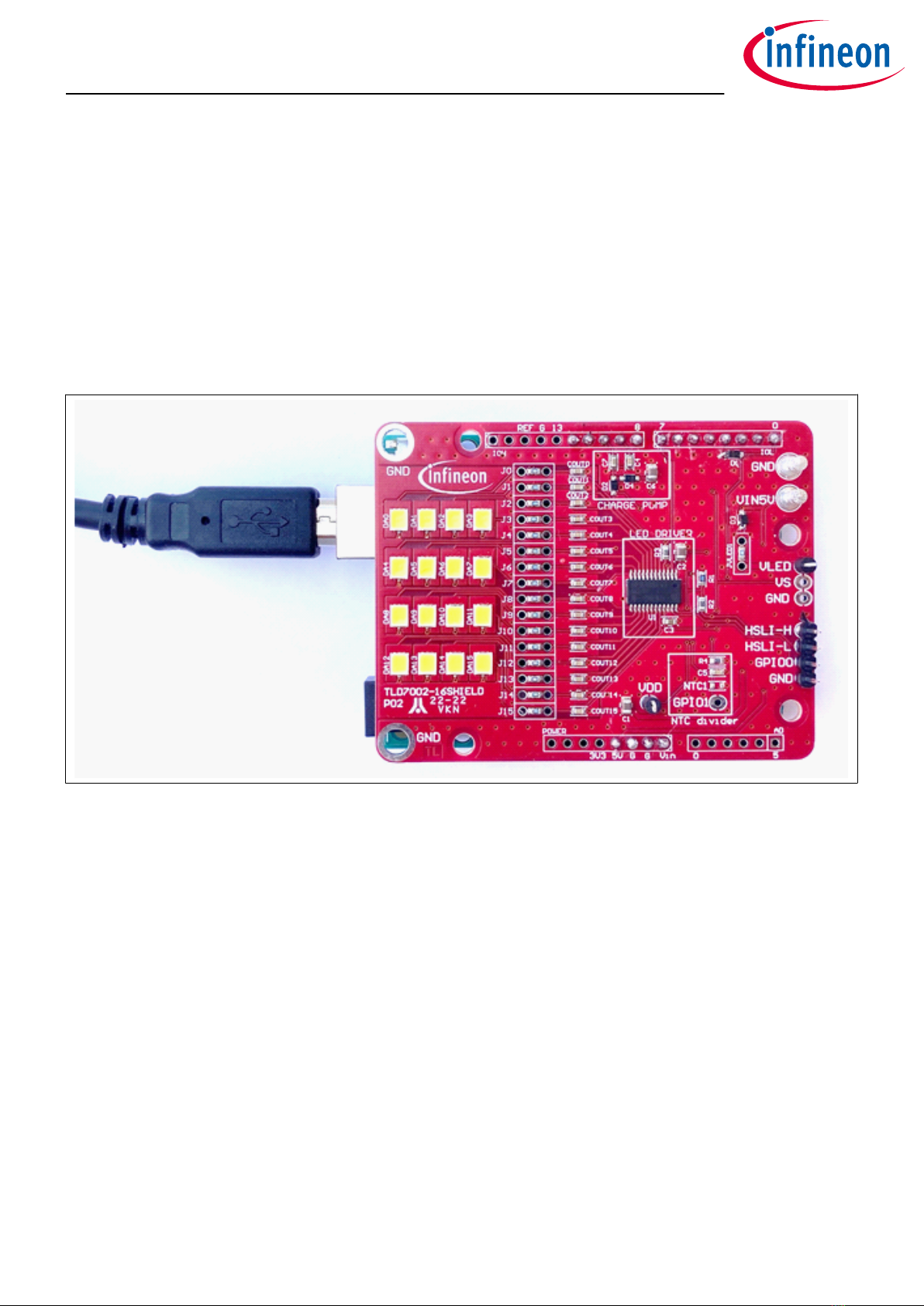
1. Download the TLD7002SHIELD_DEMO sketch from the TLD7002SHIELD webpage
2. Plug the TLD7002SHIELD on the Arduino UNO board
3. Connect the TLD7002SHIELD to the PC with a USB cable
4. Download and open the Arduino IDE [1]
5. Select the correct COM PORT on the Tools > Port menu
6. Upload the TLD7002SHIELD_DEMO sketch in the Arduino UNO
7. Press BUTTON on TLD7002-16SHIELD to change the animation
8. Optional: open Tools > Serial Monitor and set the speed to 230400 bps to see diagnostic printf
Figure 5 TLD7002-16SHIELD plugged in the Arduino UNO with USB cable
The TLD7002-16SHIELD is equipped with eicient white LEDs, therefore in order to keep the glare low, a duty
cycle is set to 10% on the TLD7002-16DEMO sketch V.1.0. The brightness can be easily increased by modifying
the provided sketch.
2.1 OTP configuration array and OTP wizard tool
The TLD7002-16SHIELD is assembled with a TLD7002-16ES device with unwritten OTP.
The TLD7002SHIELD_DEMO sketch V.1 initialize the TLD7002-16ES device by emulating the LED driver OTP with
a hard-coded configuration array:
const uint16 OTP_hex_cfg[] = {0x0000, 0x0000, 0x0000, 0x0000, 0x4D4D...};
This is needed because the TLD7002-16ES cannot be in ACTIVE mode if the OTP has not been written or
emulated.
A dierent configuration array can be easily generated by the OTP wizard tool. The OTP wizard is a GUI/tool
used to easily configure the OTP memory of the TLD7002-16ES device.
The OTP configuration array is prepared in advance. This can be easily achieved by clicking save configuration
in the OTP wizard tool. The configuration array is located at the end of the .ocfg saved file: in the
HEX_DATA_16BIT field. The file is of txt format and can be opened with a text editor.
TLD7002-16SHIELD
User guide
2 Quick start procedure
User guide 6 Rev.1.00
2022-07-26
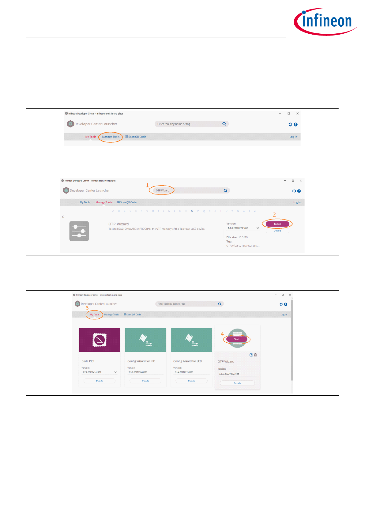
The OTP wizard GUI is installed via the Infineon Developer Center Launcher (IDC) [2] following one of the 2
installation paths:
Infineon Developer Center [3]: online repository listing all available tools, soware and services
Launcher [4]: oline utility to manage and update all tools aer downloading from the IDC online repository
Once IDC is installed, run it and click on Manage Tools.
Figure 6 Manage Tools
Then search for OTP Wizard (point 1) and click on Install (point 2).
Figure 7 Searching Tools
Once OTP wizard installation has completed, select My Tools tab (point 3) in Infineon Toolbox, then click on
Start (point 4) in OTP Wizard to start the tool.
Figure 8 Starting the OTP Wizard GUI
TLD7002-16SHIELD
User guide
2 Quick start procedure
User guide 7 Rev.1.00
2022-07-26
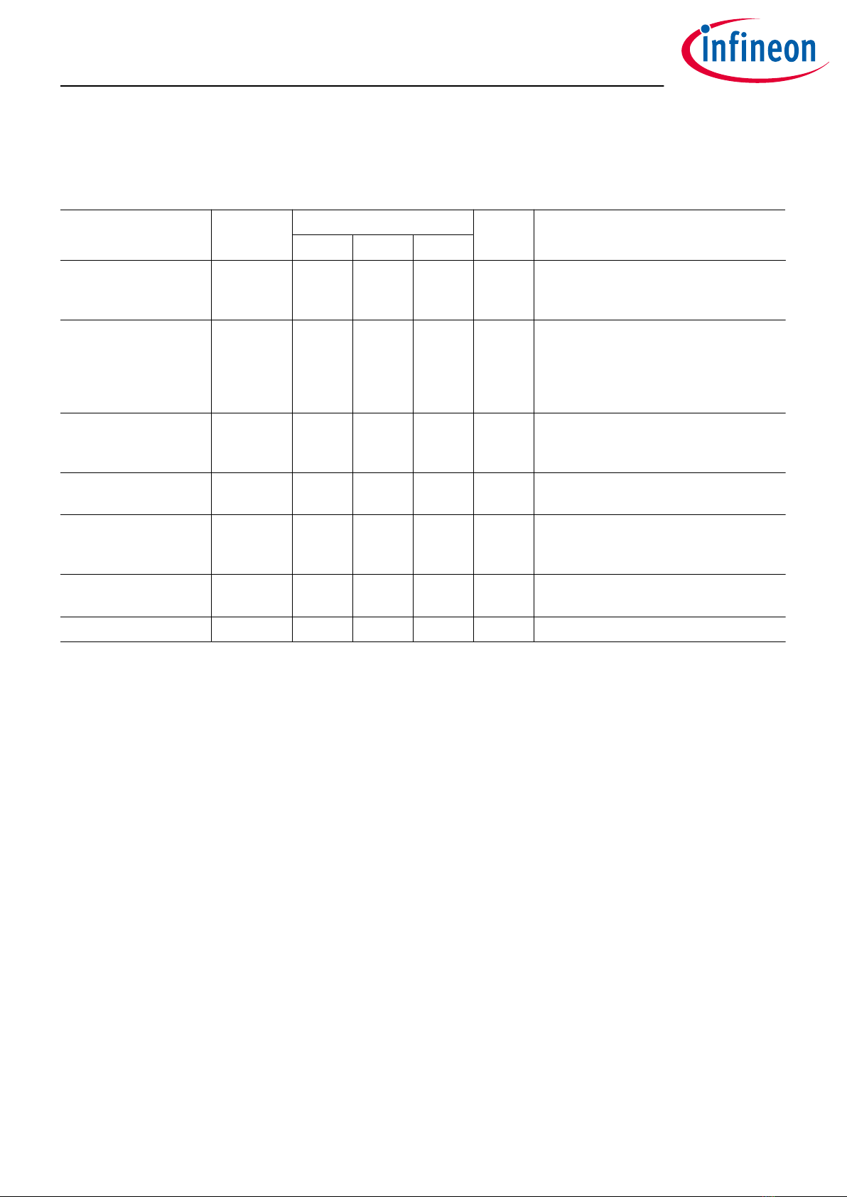
3 Electrical characteristics
Table 1 Electrical characteristics
Parameter Symbol Values Unit Note or test condition
Min. Typ. Max.
Input voltage VIN_5V 4.5 5 5.5 V VIN_5V is directly connected to
Arduino 5 V, voltage higher than 5.5 V
will damage your Arduino UNO
Input current IIN_5V 50 470 1300 mA TLD7002SHIELD_DEMO sketch sets
OUT current to 25 mA per channel.
If duty cycle is modified to 100%
and all outputs are ON, then the 5 V
current will be approximately 470 mA
LED power supply VLED 4.5 – 35 V VLED can be as low as 0 V if JVLED
jumper is open and JVLED resistor
not populated
TLD7002-16ES power
supply
VS6 – 20 V –
Output voltage VOUT_n 0 – 20 V Diagnostic setting has to be adapted
in the OTP configuration file for the
shield to be used with dierent loads
Output current IOUT_n 5.6 – 76.5 mA TLD7002SHIELD_DEMO V1 is set to
25 mA
PWM frequency fPWM 99.9 – 1997 Hz –
The input current on the TLD7002-16SHIELD is equal to the sum of all of the following:
• The LED currents multiplied by their duty cycle
• The TLD7002-16ES supply current (VS pin) multiplied by 2, due to the charge pump
• The Arduino UNO supply current
In the provided sketch the output current is set to 20 mA per channel, if duty cycle is set to 100% and all outputs
are ON, the current consumption would be approximately:
I5V_REF =IOUT_n⋅16 +IV S_typ +IArduinoUNO_typ =25mA ⋅16 +15mA ⋅2+40mA =470mA (1)
TLD7002-16SHIELD
User guide
3 Electrical characteristics
User guide 8 Rev.1.00
2022-07-26
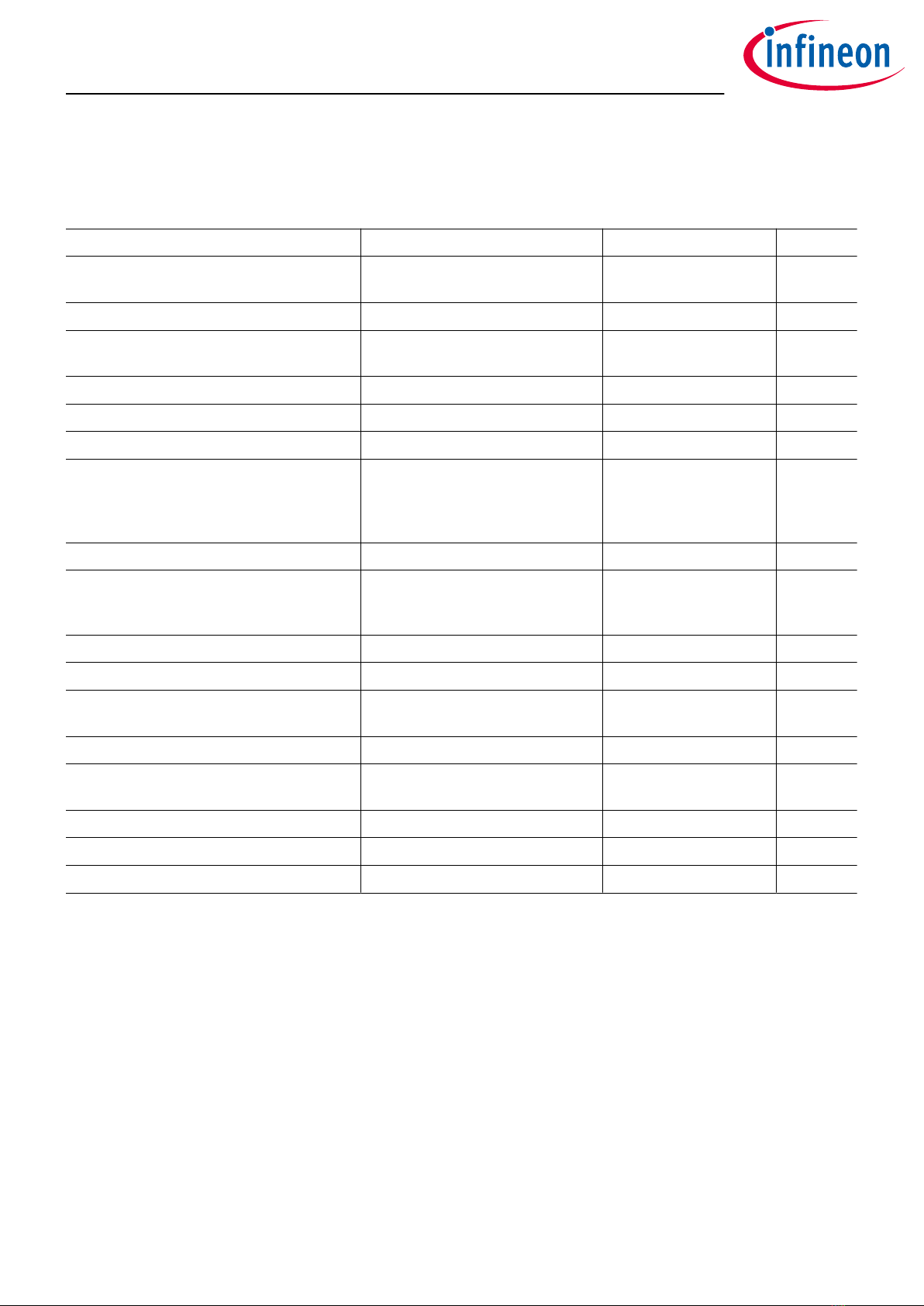
4 Bill of material
Table 2 Bill of material
Designator Description Footprint Quantity
5V, GND3, GND4, GPIO0, GPIO1, HSLI-H,
HSLI-L, VDD, VLED, VS, VS_REV
NO_POP_KEYSTONE 5117-1 TESTPAD KEYSTONE
5117-1
11
AD NO_POP_Head 6 STRIP 6V P2.54 MD 1
BUTTON PTS636 SK25F SMTR LFS PULS 6,1X3,5 SMD C&K
PTS636 F
1
C1, C2, C6 4.7uF 25V 0805 C0805 3
C3, C4, C7 470nF 25V 0603 C0603 3
C5 100nF 16V 0603 C0603 1
COUT0, COUT1, COUT2, COUT3, COUT4,
COUT5, COUT6, COUT7, COUT8, COUT9,
COUT10, COUT11, COUT12, COUT13,
COUT14, COUT15
10nF C0603 16
D1, D2, D3, D4, D5, D6 BAS3010A-03W SOD323F 6
DA0, DA1, DA2, DA3, DA4, DA5, DA6, DA7,
DA8, DA9, DA10, DA11, DA12, DA13, DA14,
DA15
JB2835AWT-W-H30 LED SMD 2835 CREE
JE2835AWTE
16
IOH NO_POP_Head 10 STRIP 10V P2.54 MD 1
IOL, POWER NO_POP_Head 8 STRIP P2.54 2
J0, J1, J2, J3, J4, J5, J6, J7, J8, J9, J10,
J11, J12, J13, J14, J15, JVLED
0R 0603 17
JBUT NO_POP TSW-102-08-G-S STRIP P2.54 1
NTC1 Mitsubishi TD11-3H103F
NTC(0603 10K 3370K)
R0603 1
R1 10k 1% 0603 R0603 1
R2, R3, R4, R5 4k7 1% 0603 R0603 4
U1 TLD7002-16ES PG-TSDSO-24 1
TLD7002-16SHIELD
User guide
4 Bill of material
User guide 9 Rev.1.00
2022-07-26

5 PCB layout
TL
TLD7002-16SHIELD
P04
NTC divider
GND
GND
GND
GND
GND
LED DRIVER
3V3
CHARGE PUMP
8
13 70
G
G5V
G
REF
5
Vin 0
VS
R5
JBUT
D6
D5
BUTTON 5V
DA10
JVLED
C3
R4
J15
J14
J13
J12
J11
J10
J9
J8
J7
J6
J5
J4
J3
J2
J1
J0
C6
C2
C1
VDD
R2
D2
D3
D4
C7
C4
5V_REV
COUT15
COUT14
COUT13
COUT12
COUT11
COUT10
COUT9
COUT8
COUT7
COUT6
COUT5
COUT4
COUT3
COUT2
COUT1
COUT0
U1
VS_REV
VLED
NTC1
HSLI-L
HSLI-H
GPIO1
GPIO0
DA15DA14DA13DA12
DA11
DA9DA8
DA7DA6DA5DA4
DA3DA2DA1DA0
POWER
IOL
IOH
AD
R3
R1
D1
C5
PA5V01
CO5V
PA5V0REV01
CO5V0REV
PAAD03
PAAD04
PAAD05
PAAD06 PAAD02 PAAD01
COAD
PABUTTON01
PABUTTON02
COBUTTON
PAC101
PAC102
COC1
PAC201
PAC202
COC2
PAC302 PAC301
COC3
PAC401
PAC402
COC4
PAC502 PAC501
COC5
PAC602
PAC601
COC6
PAC701
PAC702
COC7
PACOUT001
PACOUT002
COCOUT0
PACOUT102 PACOUT101
COCOUT1
PACOUT201
PACOUT202
COCOUT2
PACOUT302 PACOUT301
COCOUT3
PACOUT401
PACOUT402
COCOUT4
PACOUT502 PACOUT501
COCOUT5
PACOUT601
PACOUT602
COCOUT6
PACOUT702 PACOUT701
COCOUT7
PACOUT801
PACOUT802
COCOUT8
PACOUT902 PACOUT901
COCOUT9
PACOUT1001
PACOUT1002
COCOUT10
PACOUT1102 PACOUT1101
COCOUT11
PACOUT1201
PACOUT1202
COCOUT12
PACOUT1302 PACOUT1301
COCOUT13
PACOUT1401
PACOUT1402
COCOUT14
PACOUT1502 PACOUT1501
COCOUT15
PAD10A
PAD10K
COD1
PAD20K
PAD20A
COD2
PAD30A
PAD30K
COD3
PAD40K
PAD40A
COD4
PAD50A
PAD50K
COD5
PAD60K PAD60A
COD6
PADA00A
PADA00K
CODA0
PADA10A
PADA10K
CODA1
PADA20A
PADA20K
CODA2
PADA30A
PADA30K
CODA3
PADA40A
PADA40K
CODA4
PADA50A
PADA50K
CODA5
PADA60A
PADA60K
CODA6
PADA70A
PADA70K
CODA7
PADA80A
PADA80K
CODA8
PADA90A
PADA90K
CODA9
PADA100A
PADA100K
CODA10
PADA110A
PADA110K
CODA11
PADA120A
PADA120K
CODA12
PADA130A
PADA130K
CODA13
PADA140A
PADA140K
CODA14
PADA150A
PADA150K
CODA15
PAGND101
COGND1
PAGND201
COGND2
PAGND301
COGND3
PAGND401
COGND4
PAGND501
COGND5
PAGPIO001
COGPIO0
PAGPIO101
COGPIO1
PAHSLI0H01
COHSLI0H
PAHSLI0L01
COHSLI0L
PAIOH03 PAIOH04 PAIOH05 PAIOH06
PAIOH02
PAIOH01 PAIOH07 PAIOH08 PAIOH09
PAIOH010
COIOH
PAIOL08
PAIOL07
PAIOL01 PAIOL02 PAIOL06
PAIOL05
PAIOL04
PAIOL03
COIOL
PAJ002 PAJ001
COJ0
PAJ101
PAJ102
COJ1
PAJ202 PAJ201
COJ2
PAJ301
PAJ302
COJ3
PAJ402 PAJ401
COJ4
PAJ501
PAJ502
COJ5
PAJ602 PAJ601
COJ6
PAJ701
PAJ702
COJ7
PAJ802 PAJ801
COJ8
PAJ901
PAJ902
COJ9
PAJ1002 PAJ1001
COJ10
PAJ1101
PAJ1102
COJ11
PAJ1202 PAJ1201
COJ12
PAJ1301
PAJ1302
COJ13
PAJ1402 PAJ1401
COJ14
PAJ1501
PAJ1502
COJ15
PAJBUT01
PAJBUT02
COJBUT
PAJVLED02
PAJVLED01
COJVLED
COMK10
PANTC101
PANTC102
CONTC1
PAPOWER08 PAPOWER07 PAPOWER01
PAPOWER02
PAPOWER06 PAPOWER05 PAPOWER04 PAPOWER03
COPOWER
PAR102
PAR101
COR1
PAR201
PAR202
COR2
PAR302
PAR301
COR3
PAR402 PAR401
COR4
PAR502
PAR501
COR5
PAU10EP
PAU1020
PAU1019
PAU1018
PAU1017
PAU1016
PAU1015
PAU1014
PAU1013
PAU1012 PAU1010
PAU109 PAU108 PAU107 PAU106 PAU105 PAU104 PAU103 PAU102
PAU101
PAU1011
PAU1024
PAU1023
PAU1022
PAU1021
COU1
PAVDD01
COVDD
PAVLED01
COVLED
PAVS01
COVS
PAVS0REV01
COVS0REV
PA5V01
PAD20A
PAD30A
PAD50K
PAPOWER04
PABUTTON02
PAIOL03
PAJBUT01
PAC401
PAIOH09
PAC701
PAIOH08
PABUTTON01
PAC101
PAC201
PAC301
PAC501
PAC601
PAGND101
PAGND201
PAGND301
PAGND401
PAGND501
PAJBUT02
PANTC101
PAPOWER02
PAPOWER03
PAR401
PAU1022
PAU10EP
PAGPIO001
PAIOL01
PAU102
PAC502
PANTC102
PAR101
PAR501
PAU103
PAHSLI0H01
PAR201
PAR402
PAU1024
PAD10A
PAHSLI0L01
PAIOL08
PAU1023
PAC202
PAR102
PAR202
PAU101
PAVDD01
PA5V0REV01
PAD50A
PAC402
PAC702
PAD20K
PAD40A
PAD30K
PAJVLED02
PAD60A PAVS0REV01
PADA00K
PAJ002
PADA10K
PAJ102
PADA20K
PAJ202
PADA30K
PAJ302
PADA40K
PAJ402
PADA50K
PAJ502
PADA60K
PAJ602
PADA70K
PAJ702
PADA80K
PAJ802
PADA90K
PAJ902
PADA100K
PAJ1002
PADA110K
PAJ1102
PADA120K
PAJ1202
PADA130K
PAJ1302
PADA140K
PAJ1402
PADA150K
PAJ1502
PAGPIO101
PAR502
PAR302
PAU104
PACOUT002
PAJ001
PAU105
PACOUT102
PAJ101
PAU106
PACOUT202
PAJ201
PAU107
PACOUT302
PAJ301
PAU108
PACOUT402
PAJ401
PAU109
PACOUT502
PAJ501
PAU1010
PACOUT602
PAJ601
PAU1011
PACOUT702
PAJ701
PAU1012
PACOUT802
PAJ801
PAU1013
PACOUT902
PAJ901
PAU1014
PACOUT1002
PAJ1001
PAU1015
PACOUT1102
PAJ1101
PAU1016
PACOUT1202
PAJ1201
PAU1017
PACOUT1302
PAJ1301
PAU1018
PACOUT1402
PAJ1401
PAU1019
PACOUT1502
PAJ1501
PAU1020
PAD10K
PAIOL05
PAPOWER01
PAC102
PACOUT001
PACOUT101
PACOUT201
PACOUT301
PACOUT401
PACOUT501
PACOUT601
PACOUT701
PACOUT801
PACOUT901
PACOUT1001
PACOUT1101
PACOUT1201
PACOUT1301
PACOUT1401
PACOUT1501
PADA00A PADA10A PADA20A PADA30A
PADA40A PADA50A PADA60A PADA70A
PADA80A PADA90A
PADA100A PADA110A
PADA120A PADA130A PADA140A PADA150A
PAJVLED01
PAR301
PAVLED01
PAC302
PAC602
PAD40K
PAD60K
PAU1021
PAVS01
Figure 9 PCB layout top
PA5V01
CO5V
PA5V0REV01
CO5V0REV
PAAD03
PAAD04
PAAD05
PAAD06 PAAD02 PAAD01
COAD
PABUTTON01
PABUTTON02
COBUTTON
PAC101
PAC102
COC1
PAC201
PAC202
COC2
PAC302 PAC301
COC3
PAC401
PAC402
COC4
PAC502 PAC501
COC5
PAC602
PAC601
COC6
PAC701
PAC702
COC7
PACOUT001
PACOUT002
COCOUT0
PACOUT102 PACOUT101
COCOUT1
PACOUT201
PACOUT202
COCOUT2
PACOUT302 PACOUT301
COCOUT3
PACOUT401
PACOUT402
COCOUT4
PACOUT502 PACOUT501
COCOUT5
PACOUT601
PACOUT602
COCOUT6
PACOUT702 PACOUT701
COCOUT7
PACOUT801
PACOUT802
COCOUT8
PACOUT902 PACOUT901
COCOUT9
PACOUT1001
PACOUT1002
COCOUT10
PACOUT1102 PACOUT1101
COCOUT11
PACOUT1201
PACOUT1202
COCOUT12
PACOUT1302 PACOUT1301
COCOUT13
PACOUT1401
PACOUT1402
COCOUT14
PACOUT1502 PACOUT1501
COCOUT15
PAD10A
PAD10K
COD1
PAD20K
PAD20A
COD2
PAD30A
PAD30K
COD3
PAD40K
PAD40A
COD4
PAD50A
PAD50K
COD5
PAD60K PAD60A
COD6
PADA00A
PADA00K
CODA0
PADA10A
PADA10K
CODA1
PADA20A
PADA20K
CODA2
PADA30A
PADA30K
CODA3
PADA40A
PADA40K
CODA4
PADA50A
PADA50K
CODA5
PADA60A
PADA60K
CODA6
PADA70A
PADA70K
CODA7
PADA80A
PADA80K
CODA8
PADA90A
PADA90K
CODA9
PADA100A
PADA100K
CODA10
PADA110A
PADA110K
CODA11
PADA120A
PADA120K
CODA12
PADA130A
PADA130K
CODA13
PADA140A
PADA140K
CODA14
PADA150A
PADA150K
CODA15
PAGND101
COGND1
PAGND201
COGND2
PAGND301
COGND3
PAGND401
COGND4
PAGND501
COGND5
PAGPIO001
COGPIO0
PAGPIO101
COGPIO1
PAHSLI0H01
COHSLI0H
PAHSLI0L01
COHSLI0L
PAIOH03 PAIOH04 PAIOH05 PAIOH06
PAIOH02
PAIOH01 PAIOH07 PAIOH08 PAIOH09
PAIOH010
COIOH
PAIOL08
PAIOL07
PAIOL01 PAIOL02 PAIOL06
PAIOL05
PAIOL04
PAIOL03
COIOL
PAJ002 PAJ001
COJ0
PAJ101
PAJ102
COJ1
PAJ202 PAJ201
COJ2
PAJ301
PAJ302
COJ3
PAJ402 PAJ401
COJ4
PAJ501
PAJ502
COJ5
PAJ602 PAJ601
COJ6
PAJ701
PAJ702
COJ7
PAJ802 PAJ801
COJ8
PAJ901
PAJ902
COJ9
PAJ1002 PAJ1001
COJ10
PAJ1101
PAJ1102
COJ11
PAJ1202 PAJ1201
COJ12
PAJ1301
PAJ1302
COJ13
PAJ1402 PAJ1401
COJ14
PAJ1501
PAJ1502
COJ15
PAJBUT01
PAJBUT02
COJBUT
PAJVLED02
PAJVLED01
COJVLED
COMK10
PANTC101
PANTC102
CONTC1
PAPOWER08 PAPOWER07 PAPOWER01
PAPOWER02
PAPOWER06 PAPOWER05 PAPOWER04 PAPOWER03
COPOWER
PAR102
PAR101
COR1
PAR201
PAR202
COR2
PAR302
PAR301
COR3
PAR402 PAR401
COR4
PAR502
PAR501
COR5
PAU10EP
PAU1020
PAU1019
PAU1018
PAU1017
PAU1016
PAU1015
PAU1014
PAU1013
PAU1012 PAU1010
PAU109 PAU108 PAU107 PAU106 PAU105 PAU104 PAU103 PAU102
PAU101
PAU1011
PAU1024
PAU1023
PAU1022
PAU1021
COU1
PAVDD01
COVDD
PAVLED01
COVLED
PAVS01
COVS
PAVS0REV01
COVS0REV
PA5V01
PAD20A
PAD30A
PAD50K
PAPOWER04
PABUTTON02
PAIOL03
PAJBUT01
PAC401
PAIOH09
PAC701
PAIOH08
PABUTTON01
PAC101
PAC201
PAC301
PAC501
PAC601
PAGND101
PAGND201
PAGND301
PAGND401
PAGND501
PAJBUT02
PANTC101
PAPOWER02
PAPOWER03
PAR401
PAU1022
PAU10EP
PAGPIO001
PAIOL01
PAU102
PAC502
PANTC102
PAR101
PAR501
PAU103
PAHSLI0H01
PAR201
PAR402
PAU1024
PAD10A
PAHSLI0L01
PAIOL08
PAU1023
PAC202
PAR102
PAR202
PAU101
PAVDD01
PA5V0REV01
PAD50A
PAC402
PAC702
PAD20K
PAD40A
PAD30K
PAJVLED02
PAD60A PAVS0REV01
PADA00K
PAJ002
PADA10K
PAJ102
PADA20K
PAJ202
PADA30K
PAJ302
PADA40K
PAJ402
PADA50K
PAJ502
PADA60K
PAJ602
PADA70K
PAJ702
PADA80K
PAJ802
PADA90K
PAJ902
PADA100K
PAJ1002
PADA110K
PAJ1102
PADA120K
PAJ1202
PADA130K
PAJ1302
PADA140K
PAJ1402
PADA150K
PAJ1502
PAGPIO101
PAR502
PAR302
PAU104
PACOUT002
PAJ001
PAU105
PACOUT102
PAJ101
PAU106
PACOUT202
PAJ201
PAU107
PACOUT302
PAJ301
PAU108
PACOUT402
PAJ401
PAU109
PACOUT502
PAJ501
PAU1010
PACOUT602
PAJ601
PAU1011
PACOUT702
PAJ701
PAU1012
PACOUT802
PAJ801
PAU1013
PACOUT902
PAJ901
PAU1014
PACOUT1002
PAJ1001
PAU1015
PACOUT1102
PAJ1101
PAU1016
PACOUT1202
PAJ1201
PAU1017
PACOUT1302
PAJ1301
PAU1018
PACOUT1402
PAJ1401
PAU1019
PACOUT1502
PAJ1501
PAU1020
PAD10K
PAIOL05
PAPOWER01
PAC102
PACOUT001
PACOUT101
PACOUT201
PACOUT301
PACOUT401
PACOUT501
PACOUT601
PACOUT701
PACOUT801
PACOUT901
PACOUT1001
PACOUT1101
PACOUT1201
PACOUT1301
PACOUT1401
PACOUT1501
PADA00A PADA10A PADA20A PADA30A
PADA40A PADA50A PADA60A PADA70A
PADA80A PADA90A
PADA100A PADA110A
PADA120A PADA130A PADA140A PADA150A
PAJVLED01
PAR301
PAVLED01
PAC302
PAC602
PAD40K
PAD60K
PAU1021
PAVS01
Figure 10 PCB layout bottom
TLD7002-16SHIELD
User guide
5 PCB layout
User guide 10 Rev.1.00
2022-07-26

6 Schematics
0
1
2
3
4
0
1
2
3
4
5
6
7
8
9
5
6
7
8
9
!
"
#
$
#
%
%
#
#
$
&
'
("
("
)**)))
*)))
+,"
+,"
*
-."
/0/1-"/1(
1-"/1()2+30
)2+30-1(
(4 $54
$54 6"
+
7
89:;
<
2
=
>
?
4
@
<
3
0
A
B
3
5
7
5
6
5
5
5
C
D
;
E
E
F
F
G
G
H
H
I
J
J
K
K
L
M
=
B
M
N
O
M
O
N
N
P
Q
R
S
9
8
7
6
U
V
5
?
V
C
;
E
F
G
H
I
0
3
B
M
N
O
M
O
N
P
Q
R
S
0
C
0
5
0
6
0
7
0
8
0
9
;
;
;
W
E
E
X
X
F
K
G
J
H
I
L
M
P
B
M
N
O
M
O
N
P
Q
R
S
5
C
;
;
E
E
F
F
G
H
H
I
I
J
J
K
K
O
M
Y4
Y4
?
B
M
N
O
M
O
N
N
P
Q
R
S
89:
>
>
L
B
Z
Z
7
>
7
Z
Z
9
>
A
B
3
A
B
3
Z
Z
9
>
?
?
4
<
4
U
B
B
2
[
\
]
^
_
`
ab
c
a`
a`
`
dc
dc
ea
ea
\
f
4
g
h
i
j
Q
S
O
R
S
k
2
i
l
l
Q
m
n
n
i
Q
g
n
Q
o
l
R
p
q
Q
R
n
j
h
o
Q
R
S
r
l
s
t
uv
uv
:w
:w
x
::
::
A
O
L
M
5
A
O
L
M
C
P
<
=
L
y
=
P
<
=
L
y
P
2
M
z
U
5
9
5
C
l
@
@
2
M
z
U
5
C
l
@
@
2
M
z
U
5
8
5
C
l
@
@
2
M
z
U
C
5
C
l
@
@
2
M
z
U
5
5
C
l
@
@
2
M
z
U
6
5
5
5
C
l
@
@
2
M
z
U
7
5
C
l
@
@
2
M
z
U
8
5
C
l
@
@
2
M
z
U
9
5
C
l
@
@
2
M
z
U
5
C
l
@
@
2
M
z
U
5
C
l
@
@
2
M
z
U
D
5
C
l
@
@
2
M
z
U
5
C
5
C
l
@
@
2
M
z
U
5
5
5
C
l
@
@
2
M
z
U
5
6
5
C
l
@
@
2
M
z
U
5
7
5
C
l
@
@
x
{
E
;
|{
|{
v
}v
}v
E
F
F
x
v
~
:
G
8
8
}9W
E
W
H
;
I
;
G
;
X
E
J
;
F
;
K
F
K
;
E
;
J
G
X
;
;
;
I
H
;
W
;
W
;
H
I
;
;
x
::
::
;
|{
|{
v
}|
}|
E
G
G
8
8
}9;
F
X
;
G
J
;
E
K
;
F
;
H
~
~
w
9
E
W
89:
E
E
~
~
z
5
U
=
3
C
C
6
y
5
4
<
N
U
3
<
89:
u
E
G
J
E
H
x
W
K
W
H
89:
x
{
x
{
x
v
~
:
x
v
~
:
x
v
~
:
x
v
~
:
x
v
~
:
x
v
~
:
x
v
~
:
x
v
~
:
x
v
~
:
x
v
~
:
x
v
~
:
x
v
~
:
x
v
~
:
x
v
~
:
x
v
~
:
x
v
~
:
x
v
~
:
uw
uw
uw
uw
:;
:;
{
F
W
;
W
W
F
P
<
=
L
y
=
x
v
~
:
89:
A
O
L
M
C
P
<
=
L
y
=
P
<
=
L
y
P
|{
|{
v
}
}
|
|{
|{
v
}
}
v
;
;
W
;
W
I
W
F
9
u
;
:
;
;
F
|
;
W
F
9
u
89:
u
H
;
W
W
;
I
x
W
I
W
F
89:
A
O
L
M
5
A
O
L
M
5
A
O
L
M
C
8
8
}W
89:
F
F
G
J
J
;
W
I
W
F
M
z
U
C
M
z
U
5
M
z
U
6
M
z
U
7
M
z
U
8
M
z
U
9
M
z
U
M
z
U
M
z
U
M
z
U
D
M
z
U
5
C
M
z
U
5
5
M
z
U
5
6
M
z
U
5
7
M
z
U
5
8
M
z
U
5
9
3
0
C
1
6
7
9
0
YU
YU
y
Y
y
P
7
C
3
0
5
1
6
7
9
0
YU
YU
y
Y
y
P
7
C
3
0
6
1
6
7
9
0
YU
YU
y
Y
y
P
7
C
3
0
7
1
6
7
9
0
YU
YU
y
Y
y
P
7
C
3
0
8
1
6
6
7
9
0
YU
YU
y
Y
y
P
7
C
3
0
9
1
1
6
6
7
9
0
YU
YU
y
Y
y
P
7
C
3
0
1
6
6
7
9
0
YU
YU
y
Y
y
P
7
C
3
0
1
6
7
9
0
YU
YU
y
Y
y
P
7
C
3
0
1
6
6
7
9
0
YU
YU
y
Y
y
P
7
C
3
0
D
1
6
6
7
9
0
YU
YU
y
Y
y
P
7
C
3
0
5
C
1
6
6
7
9
0
YU
YU
y
Y
y
P
7
C
3
0
5
5
1
1
6
6
7
9
0
YU
YU
y
Y
y
P
7
C
3
0
5
6
1
6
7
9
0
YU
YU
y
Y
y
P
7
C
3
0
5
7
1
6
7
9
0
YU
YU
y
Y
y
P
7
C
3
0
5
8
1
6
7
7
9
9
0
YU
YU
y
Y
y
P
7
C
3
0
5
9
1
6
7
9
0
YU
YU
y
Y
y
P
7
C
t
uv
uv
:w
:w
x
::
::
x
v
~
:
89:
x
::
::
E
G
J
;
W
I
W
F
G
G
J
;
W
I
W
F
89:
t
uv
uv
:w
:w
x
::
::
:F
:F
{
F
W
;
W
W
F
3
D
N
O
Y
Y
:E
:E
{
F
W
;
W
W
F
H
x
w
:}9
:
:G
:G
{
F
W
;
W
W
F
89:
u
;
G
J
E
H
x
W
K
W
H
u
I
G
J
E
H
x
W
K
W
H
3
5
C
N
O
Y
3
D
N
O
Y
Y
3
5
C
N
O
Y
x
v
~
:
x
v
~
:
H
x
w
~
~
x
x
}9w
:
89:E
89:G
89:
x
{
w
~
~
x
u
F
G
J
W
E
H
x
W
I
W
F
uG
uG
G
J
W
E
H
x
W
I
W
F
uJ
uJ
G
J
W
E
E
H
x
W
I
W
F
fbc
[
[
\
db
^
edfe
a_
a_
`
ef
ef
`
e
c
C
C
?
5
C
?
6
C
?
8
C
?
?
7
C
?
9
C
?
C
?
?
?
C
?
C
?
?
?
D
C
?
5
C
C
?
?
?
5
5
5
5
C
?
5
6
C
?
?
?
5
8
C
?
?
5
5
5
7
C
?
5
5
5
9
C
?
>
=
4
3
C
?
89:F
89:
H
x
w
:}9
:
H
x
w
:}9
:
89:H
89:
:H
:H
{
F
W
;
W
W
F
:I
:I
{
F
W
;
W
W
F
x
{
x
{
8
8
};
H
H
G
J
J
;
W
I
W
F
H
x
^
f^
eea
`
89:
;
E
1
z
U
B
M
N
O
M
O
U
<
Y
y
5
C
6
y
C
y
A
y
<
9
u
u
{
I
F
I
{
E
H
{
t
v
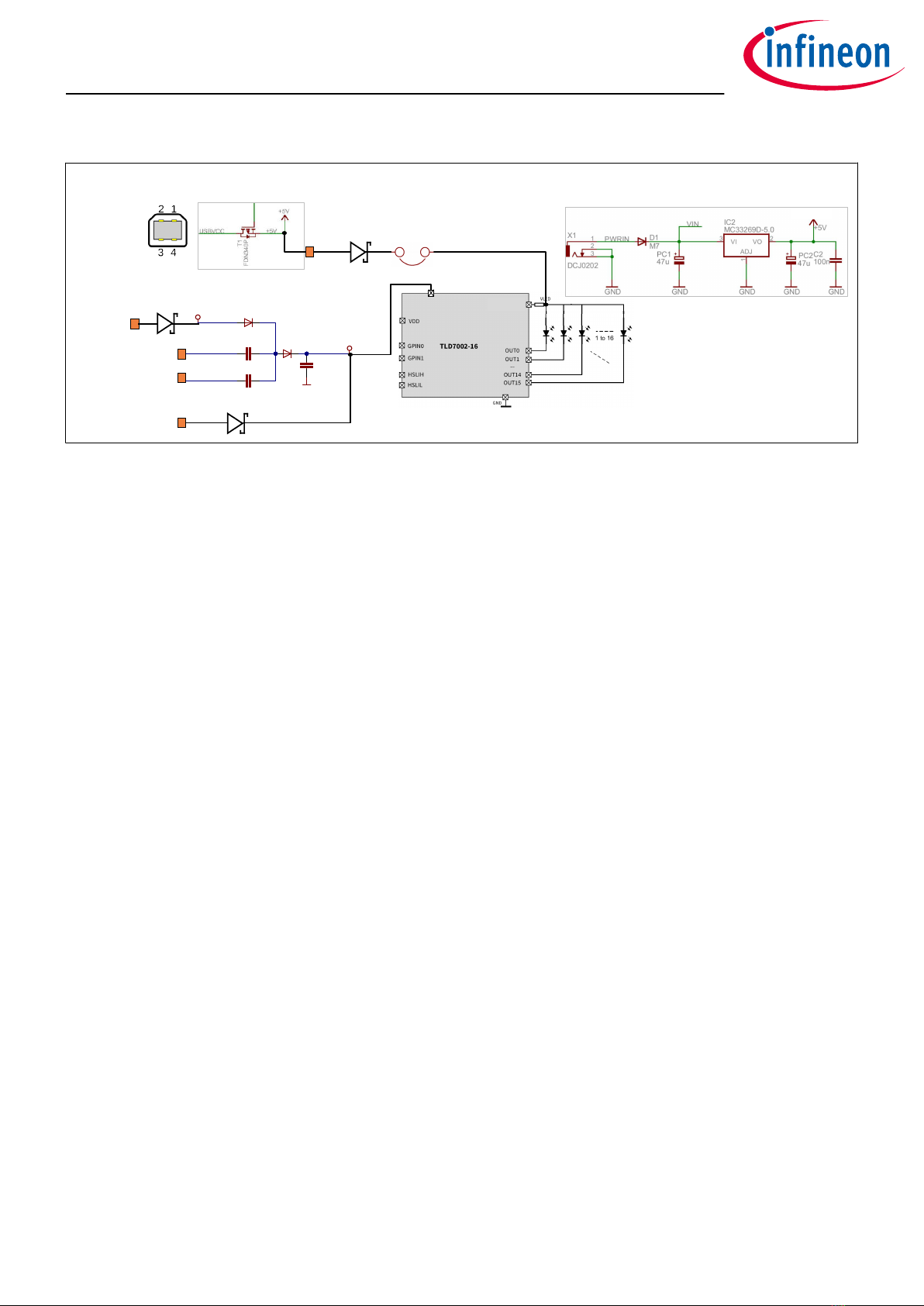
{
Figure 11 TLD7002-16ES schematic
TLD7002-16SHIELD
User guide
6 Schematics
User guide 11 Rev.1.00
2022-07-26

References
[1] Arduino IDE downloads; https://www.arduino.cc/en/soware
[2] Infineon Developer Center Launcher ; https://www.infineon.com/cms/en/design-support/tools/utilities/
infineon-developer-center-idc-launcher/
[3] Infineon Developer Center; https://sowaretools.infineon.com/welcome?
_ga=2.13126193.788892259.1654090253-547430173.1617093564
[4] Launcherhttps://sowaretools.infineon.com/tools/com.ifx.tb.launcher2
TLD7002-16SHIELD
User guide
References
User guide 12 Rev.1.00
2022-07-26

Revision history
Document
version
Date of
release
Description of changes
Rev.1.00 2022-07-26 • Initial release
TLD7002-16SHIELD
User guide
Revision history
User guide 13 Rev.1.00
2022-07-26

Trademarks
All referenced product or service names and trademarks are the property of their respective owners.
Edition 2022-07-26
Published by
Infineon Technologies AG
81726 Munich, Germany
©2022 Infineon Technologies AG
All Rights Reserved.
Do you have a question about any
aspect of this document?
Email: [email protected]om
Document reference
IFX-eyp1657185166499
Important notice
The information given in this document shall in no
event be regarded as a guarantee of conditions or
characteristics (“Beschaenheitsgarantie”).
With respect to any examples, hints or any typical
values stated herein and/or any information regarding
the application of the product, Infineon Technologies
hereby disclaims any and all warranties and liabilities
of any kind, including without limitation warranties of
non-infringement of intellectual property rights of any
third party.
In addition, any information given in this document is
subject to customer’s compliance with its obligations
stated in this document and any applicable legal
requirements, norms and standards concerning
customer’s products and any use of the product of
Infineon Technologies in customer’s applications.
The data contained in this document is exclusively
intended for technically trained sta. It is the
responsibility of customer’s technical departments to
evaluate the suitability of the product for the intended
application and the completeness of the product
information given in this document with respect to such
application.
Warnings
Due to technical requirements products may contain
dangerous substances. For information on the types
in question please contact your nearest Infineon
Technologies oice.
Except as otherwise explicitly approved by Infineon
Technologies in a written document signed by
authorized representatives of Infineon Technologies,
Infineon Technologies’ products may not be used in
any applications where a failure of the product or
any consequences of the use thereof can reasonably
be expected to result in personal injury.
Table of contents
Other Infineon DC Drive manuals


Popular DC Drive manuals by other brands


YASKAWA
YASKAWA SI-B3 Installation & technical manual

Aerotech
Aerotech Automation1 XL5e Hardware manual

Emerson
Emerson EV3150B Application guidelines

Toshiba
Toshiba T300BMV2 instruction manual

elero
elero VariEco L RH Operating and assembly instructions

GFA
GFA ELEKTROMAT ST 9.24-25.00 installation instructions