manuals.online logo
Brands
  1. Home
  2. •
  3. Brands
  4. •
  5. ABB
  6. •
  7. DC Drive
  8. •
  9. ABB 2000 Series User manual

ABB 2000 Series User manual

Other ABB DC Drive manuals

ABB ACS180 User manual

ABB

ABB ACS180 User manual

ABB +Q951 User manual

ABB

ABB +Q951 User manual

ABB ACS880 Series User manual

ABB

ABB ACS880 Series User manual

ABB InRouter 615 User manual

ABB

ABB InRouter 615 User manual

ABB ACH580-01 Series Installation manual

ABB

ABB ACH580-01 Series Installation manual

ABB ACS850-04 series User manual

ABB

ABB ACS850-04 series User manual

ABB ACS580-01 Series Owner's manual

ABB

ABB ACS580-01 Series Owner's manual

ABB ACH550-UH-011A-6 User manual

ABB

ABB ACH550-UH-011A-6 User manual

ABB ACS850 series Troubleshooting guide

ABB

ABB ACS850 series Troubleshooting guide

ABB ACH580-01 Series Installation manual

ABB

ABB ACH580-01 Series Installation manual

ABB ACS355 series Owner's manual

ABB

ABB ACS355 series Owner's manual

ABB ACS480 Installation manual

ABB

ABB ACS480 Installation manual

ABB ACS880-07 User manual

ABB

ABB ACS880-07 User manual

ABB ACS355 series User manual

ABB

ABB ACS355 series User manual

ABB ACH580 Series User manual

ABB

ABB ACH580 Series User manual

ABB ACS880-07XT Series User manual

ABB

ABB ACS880-07XT Series User manual

ABB ACS580-0P User manual

ABB

ABB ACS580-0P User manual

ABB ACS880-01 Series User manual

ABB

ABB ACS880-01 Series User manual

ABB ACS880-07LC User manual

ABB

ABB ACS880-07LC User manual

ABB DCS800 User manual

ABB

ABB DCS800 User manual

ABB ACS880+N5350 User manual

ABB

ABB ACS880+N5350 User manual

ABB ACS380 Series User manual

ABB

ABB ACS380 Series User manual

ABB ACS880-07C User manual

ABB

ABB ACS880-07C User manual

ABB ACS880 Series Owner's manual

ABB

ABB ACS880 Series Owner's manual

Popular DC Drive manuals by other brands

National Instruments NI MID-7604 user guide

National Instruments

National Instruments NI MID-7604 user guide

SOMFY Maestria WT Series instructions

SOMFY

SOMFY Maestria WT Series instructions

Danfoss VLT HVAC Design guide

Danfoss

Danfoss VLT HVAC Design guide

Trane TR150 Service manual

Trane

Trane TR150 Service manual

Chamberlain Garog D Series operating manual

Chamberlain Garog

Chamberlain Garog D Series operating manual

Parker PDS Series user guide

Parker

Parker PDS Series user guide

Binks QS-5012-1-CE Service manual

Binks

Binks QS-5012-1-CE Service manual

Danfoss VLT 2800 Series Quick setup

Danfoss

Danfoss VLT 2800 Series Quick setup

YASKAWA CANopen SI-S3 Technical manual

YASKAWA

YASKAWA CANopen SI-S3 Technical manual

GE D20A6 instructions

GE

GE D20A6 instructions

Danfoss VLT AQUA Drive FC 202 operating manual

Danfoss

Danfoss VLT AQUA Drive FC 202 operating manual

Lenze PositionServo 940 user manual

Lenze

Lenze PositionServo 940 user manual

Unex MC-D-250-1000-050W-TW operating manual

Unex

Unex MC-D-250-1000-050W-TW operating manual

Geckodrive G213V manual

Geckodrive

Geckodrive G213V manual

Rockwell Automation PowerFlex 700S Programming manual

Rockwell Automation

Rockwell Automation PowerFlex 700S Programming manual

WEG DeviceNet CFW500 user manual

WEG

WEG DeviceNet CFW500 user manual

Siemens SINAMICS G List manual

Siemens

Siemens SINAMICS G List manual

Siemens SINAMICS SM150 6SL3815-7NP41-0AA1 Operating instructions & installation instructions

Siemens

Siemens SINAMICS SM150 6SL3815-7NP41-0AA1 Operating instructions & installation instructions

manuals.online logo
manuals.online logoBrands
  • About & Mission
  • Contact us
  • Privacy Policy
  • Terms and Conditions

Copyright 2025 Manuals.Online. All Rights Reserved.

ABB Automation Inc.
Instrumentation Division
125 E. County Line Road
Warminster, PA 18974 USA
Tel: +1 215-674-6000
Fax: +1 215-674-7183 ABB Automation
Customer Support
ABB Instrumentation provides a comprehensive after sales service via a
Worldwide Service Organization. Contact one of the following offices for details on
your nearest Service and Repair Centre.
United Kingdom
ABB Kent-Taylor Limited
Tel: +44 (0)1480 475321
Fax: +44 (0)1480 470787
United States of America
ABB Instrumentation Inc.
Tel: +1 716 2926050
Fax: +1 716 2736207
Client Warranty
Prior to installation, the equipment referred to in this manual must be stored
in a clean, dry environment, in accordance with the Company's published
specification. Periodic checks must be made on the equipment's condition.
In the event of a failure under warranty, the following documentation must be
provided as substantiation:
1. A listing evidencing process operation and alarm logs at time of failure.
2. Copies of operating and maintenance records relating to the alleged faulty
unit.
Use of Instructions
Although Warning hazards are related to personal injury, and Caution hazards
are associated with equipment or property damage, it must be understood that
operation of damaged equipment could, under certain operational conditions,
result in degraded process system performance leading to personal injury or
death. Therefore, comply fully with all Warning and Caution notices.
Information in this manual is intended only to assist our customers in the efficient
operation of our equipment. Use of this manual for any other purpose is
specifically prohibited and its contents are not to be reproduced in full or part
without prior approval of Technical Communications Department, ABB Kent-Taylor.
Health and Safety
To ensure that our products are safe and without risk to health, the following
points must be noted:
1. The relevant sections of these instructions must be read carefully before
proceeding.
2. Warning labels on containers and packages must be observed.
3. Installation, operation, maintenance and servicing must only be carried out
by suitably trained personnel and in accordance with the information
given.
4. Normal safety precautions must be taken to avoid the possibility of an
accident occurring when operating in conditions of high pressure and/or
temperature.
5. Chemicals must be stored away from heat, protected from temperature
extremes and powders kept dry. Normal safe handling procedures must be
used.
6. When disposing of chemicals ensure that no two chemicals are mixed.
Safety advice concerning the use of the equipment described in this manual
or any relevant hazard data sheets (where applicable) may be obtained from
the Company address on the back cover, together with servicing and spares.
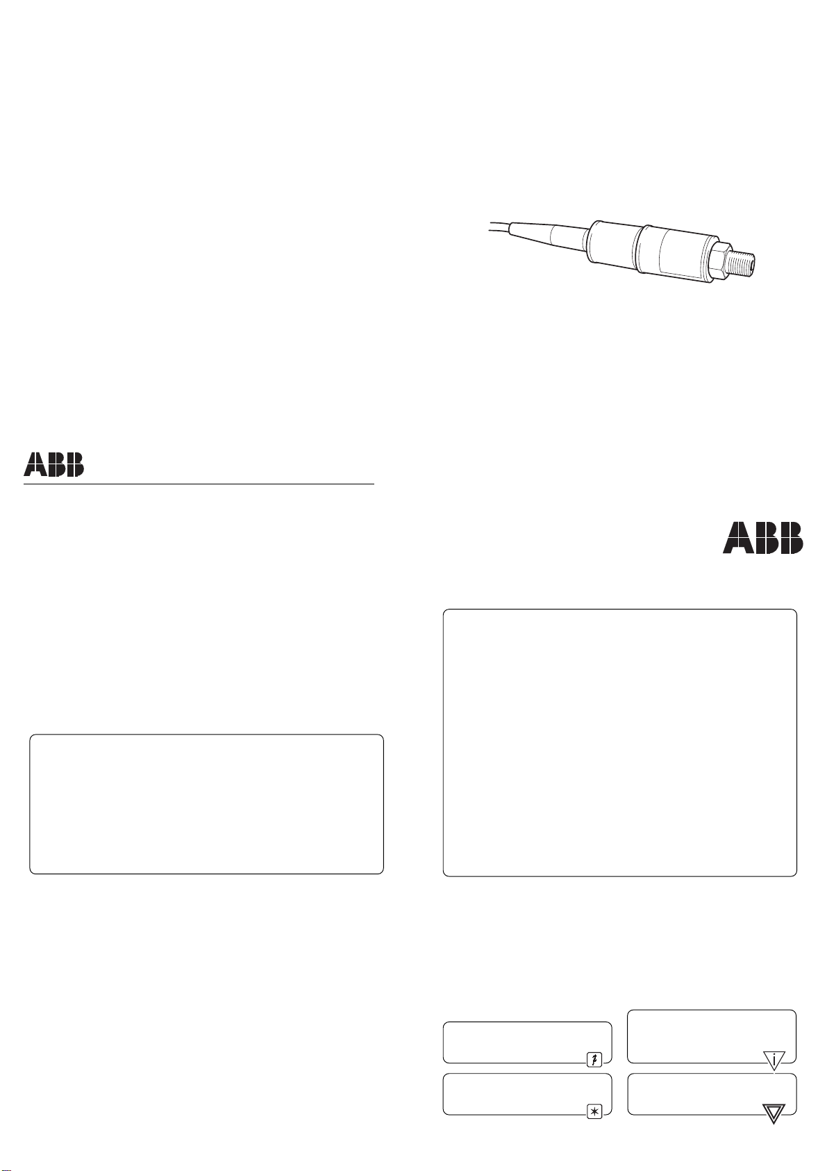
Series 2000 Pressure Transducer
The Company's policy is one of continuous product
improvement and the right is reserved to modify the
information contained herein without notice.
© ABB 1997 Printed in UK (6.97)
ABB Instrumentation Ltd.
St. Neots,
Cambs.
England, PE19 8EU
Tel: (01480) 475321
Fax: (01480) 217948
IM/2000 Issue 1
Warning.
An instruction that draws attention
to the risk of injury or death.
Caution.
An instruction that draws attention
to the risk of damage to the product,
process or surroundings.
Note.
Clarification of an instruction or
additional information.
Information.
Further reference for more detailed
information or technical details.
User Guide
1 INTRODUCTION
Information.
• Pressure range must be compatible with the maximum pressure being
measured.
• Pressure media must be compatible with the transmitter wetted parts
listed in these instructions.
• Liquid must not be allowed to freeze in the pressure port.
• Exposed ends of cables must be free from moisture.
• The gasket must be fitted under the electrical connector.
• Wetted parts:
17 – 4 PH stainless steel plus Nickle Braze to BS1845 : NK3/HTN2.
The Series 2000 Pressure Sensors are ideal for applications where a
conventional transmitter is too expensive and over specified. The Series 2000 is
a low-cost simple transducer which can be used in a large number of applications
ranging from heating and ventilation to industrial hydraulics
Series 2000 sensors can be used as a primary sensor, utilizing one of ABB’s
control products, e.g. COMMANDER 300/310 etc.
3 ELECTRICAL INSTALLATION
3.1 Electrical Connections
See Table 3.1 for electrical connections.
Electrical Connections +ve –ve case earth
Pin 1 Pin 2 Pin 4
Electrical Specifications Rated Min/Max. Milliamps
24V d.c. 12 to 36 4 to 20
3.2 Grounding
All versions should be grounded by the installation pipework. If this is not possible,
the sensor should be grounded at the instrumentation end via the appropriate pin
or green lead. For maximum protection against RFI all versions should be installed
using screened cable with the screen grounded at the instrumentation end.
3.3 Resistive Loading
The total permissible resistive load in the loop (to include all the cable resistance)
can be from ‘zero to 50 x (supply volts –12) ohms, eg. with a 24V d.c. supply the
permissible load is from zero up to 600 ohms, see Fig. 6.1.
Table 3.1 Electrical Connections and Specifications
Power
Supply
12 to 36V d.c.
Transmitter
Resistive Load
++
––
Fig. 6.1 Resistive Load
3.4 Applying Power
Before applying power, ensure the correct polarity and excitation levels are
applied.
3.5 Calibration
Transmitters are calibrated to a fixed range at time of order,identified by the fifth
and sixth letter of the identification code marked on the sensor housing
– see
Specification Sheet SS/2000.
4 MAINTENANCE
4.1 Routine Inspection
Limited to periodic inspection of the cable and connector to ensure that these are
neither damaged nor softened by incompatible liquid.
4.2 Repair
The instruments cannot be repaired locally. If damaged, return to the Company at
the address shown overleaf or to accredited dealers when a
replacement/repair is required.
2 MECHANICAL INSTALLATION
2.1 Pressure Connections
• Gl/4 external to BS 2779 compatible with ISO 228 (recommended seal
Part Number 232646-0002 or Dowty Part Number 400-021-4490-41).
2.2 Environmental Limits
• Temperature limits: –20°C to 80°C.
2.3 Dimensions – Fig. 2.1
25 (0.98)
54.6
(2.15) 6
(0.24)
27.3 (1.07)
17 (0.67)
3
(0.12)
12.4
(0.49)
19.05 (0.75) A/F Hex.
Dimensions in mm (in.)
Fig. 2.1 Sensor Dimensions