infiniDome GPSdome 1.01 User manual

GPSdome Rev 1.01/1.01-DF
Installation Manual

Page 2
Contents
...................................................................................................................................................................... 3
.......................................................................................................................................................................... 3
........................................................................................................................................................................... 4
....................................................................................................................................................................... 4
.................................................................................................................................................................. 4
....................................................................................................................... 5
............................................................................................................................................... 5
.................................................................................................................................................... 6
.......................................................................................................................................................... 8
.................................................................................................................................................................... 8
.............................................................................................................................................................. 9
........................................................................................................................................................... 9
................................................................................................................................................................ 10
............................................................................................... 11
Read instructions carefully before attempting to install
GPSdome. Retain instruction for future reference.

Page 3
Introduction
This guide details a generic instruction for the installation and operation of the GPSdome module. This
guide has been written for both static and in-vehicle applications although GPSdome may be used in a range
of applications.
This manual is written for both GPSdome 1.01 and GPSdome 1.01-DF
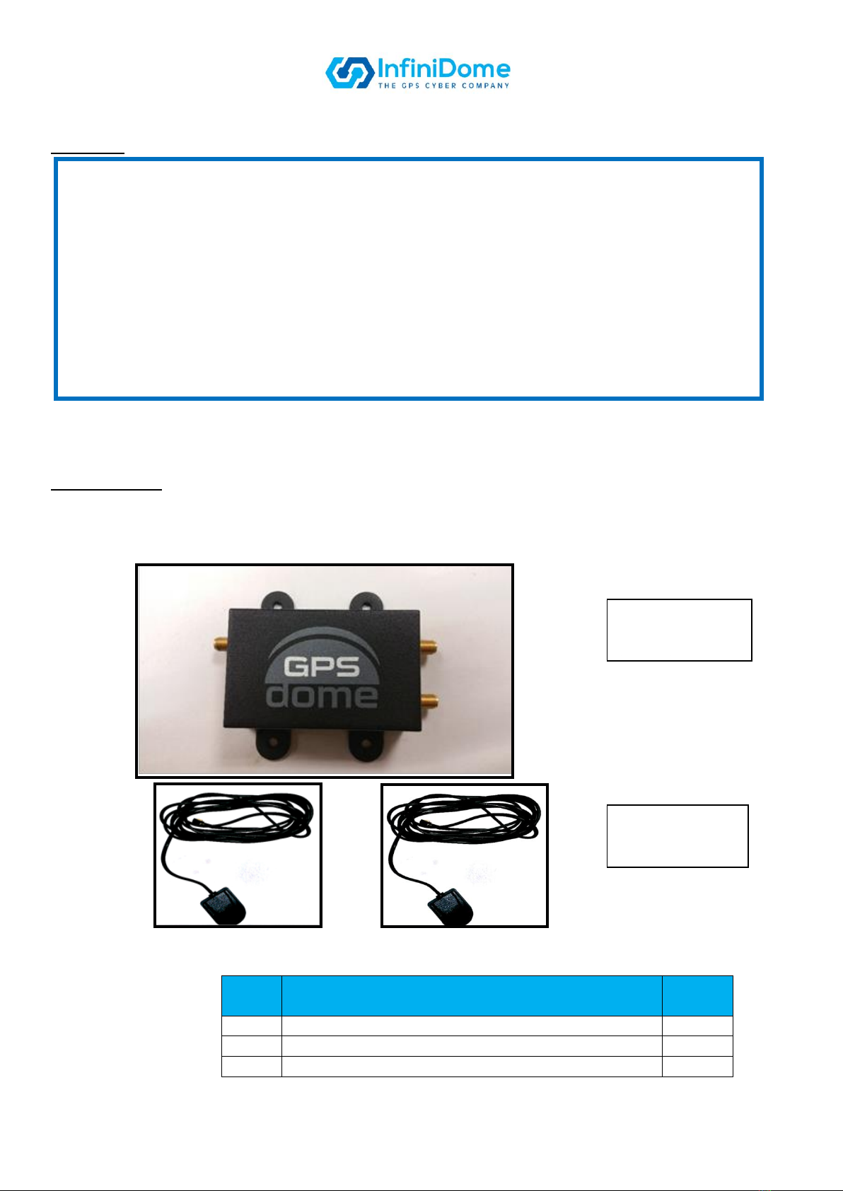
Overview
GPSdome (see Figures 1a, 1b and 2) is a compact, light-weight GPS anti-jamming module, designed to
prevent loss of position fix and time in the presence of certain types of jammers. The unit may be installed
on a range of installations that rely on GPS and it connects between the antenna and the GPS receiver.
Two active GPS antennas, with nominal gain of 26dB, are connected to the SMA RF input connectors; the
primary and auxiliary antenna inputs. The SMA RF output connector provides connection to the input of the
GPS Receiver.
Figure 1a: GPSdome 1.01 –General view
Figure 1b: GPSdome 1.01-DF –General view
RF output to GPS
receiver + DC feed
from receiver (R)
Primary antenna
input (P)
Auxiliary antenna
input (A)
RF output to
GPS receiver
Primary antenna
input (P)
Auxiliary antenna
input (A)
Input power + Jam
indication (3W)
Page 4
Cautions
Installation
Installation Kit
Open the GPSdome package to check that the contents of the kit had been supplied as shown in Figure 2 and
Table 1. Refer to the specifications details on page 13.
Figure 2: GPSdome Box Contents
Item
No.
Description
Qty.
1
GPSdome 1.01 or GPSdome 1.01-DF
1
2
Taoglas AA.105.301111, Reference Antennas*
2
3
Installation & User Guide (this Guide as required)
1
Table 1: GPSdome Box Contents
* Note: The Taoglas antenna are supplied for initial units only. For series units they may be supplied on specific requests only.
(1) The GPSdome module should be mounted on a flat surface where possible and secured
using the mounting holes provided.
(2) To prevent damage to any cable assemblies used in this installation, ensure that cables
are not bent, deformed or snagged to cause damage to the internal wiring or the
connector ends.
(3) This product is a high-tech electronics module; we recommend installation is
undertaken by a professional.
(4) During installation, ensure there is NO power applied to the module OR the GPS
receiver.
(5) When making power connections to the GPSdome 1.01-DF, verify correct polarity.
Connecting power with reverse polarity will damage the unit and void warranty.
Item 1:
GPSdome 1.01 or
1.01-DF unit
(QTY x1)
Item 2:
TAOGLAS Antenna
(QTY x2)
Page 5
GPS Receiver System with GPSdome
The GPSdome module is integrated into the static or vehicle GPS receiver as shown in Figure 3a and 3b.
Two antennas are connected to the module (supplied antennas or locally purchased for permanent
installation); the GPS antenna connects to primary input ‘P’ and an additional antenna connects to the
auxiliary input ‘A.’
Figure 3a: GPS Receiver with GPSdome 1.01 Integrated
Figure 3b: GPS Receiver with GPSdome 1.01-DF Integrated
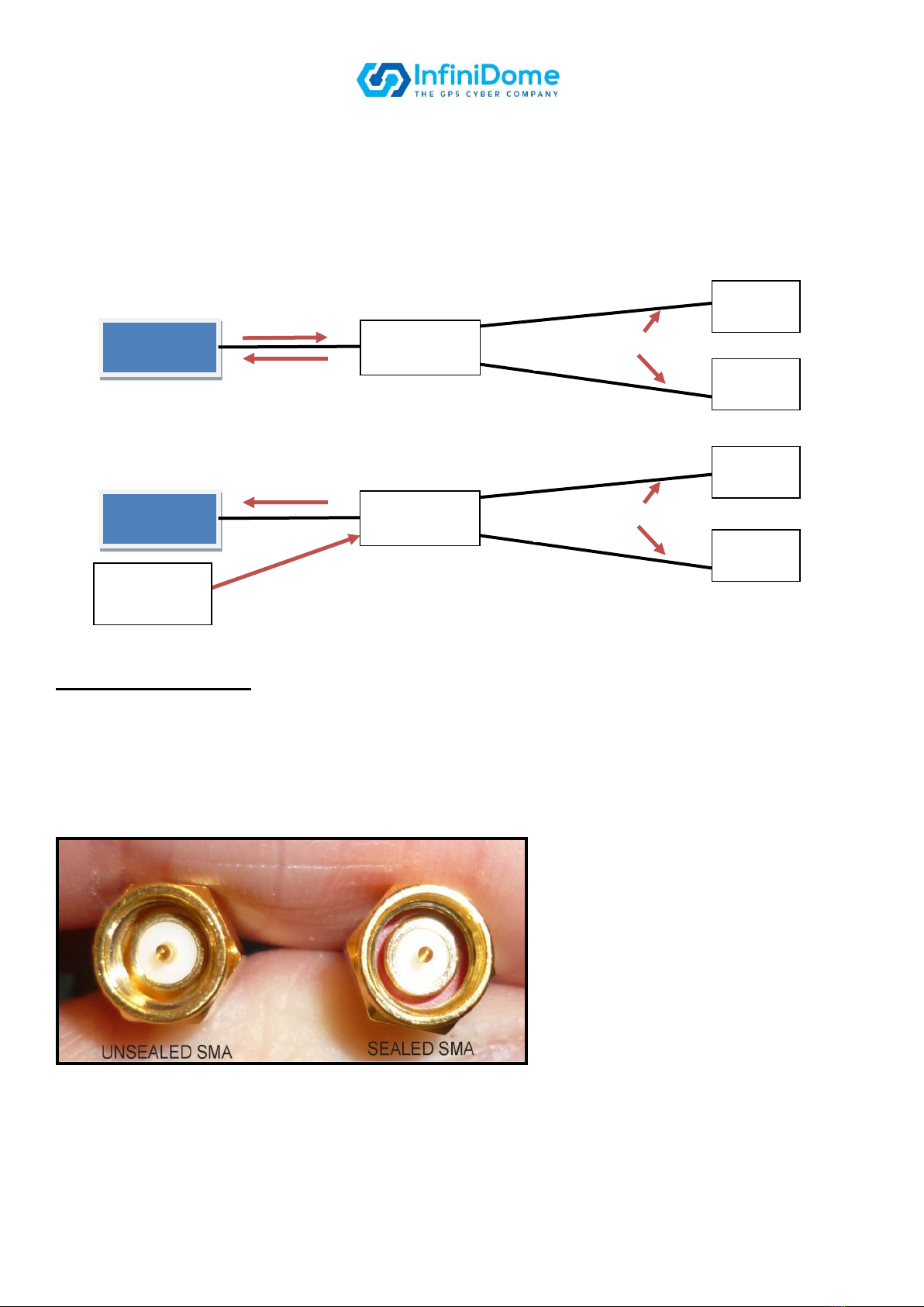
SMA Cables Connectors
To prevent the risk of moisture ingress, it is recommended that a cable with high quality sealed SMA
connectors (see Figure 4) is used to connect between the GPSdome module and the GPS receiver unit. The
cable must be of a high RF specification, and a good double shielded cable is recommended, such as Times
Microwave LMR-100A-PVC. Single shielded coaxial cable is not suitable. If alternative antennas are
installed the same cable specification and SMA connectors are required.
Figure 4: Unsealed and Sealed SMA Connectors
GPS RF signal at
1575MHz to receiver
Power DC
feed 3-12V
GPS RF signal at
1575MHz to receiver
Power DC feed 3-12V
GPS Receiver
(Existing)
GPSdome
Active
Antenna
Active
Antenna
DC feed 2.75VDC
& GPS Signal
GPS Receiver
(Existing)
GPSdome
Active
Antenna
DC feed 2.75VDC
& GPS Signal
Active
Antenna
Power Source
(Existing)

Page 6
Installation Procedure
Before commencing the installation procedure read the CAUTIONS detailed on page 4. The following
instructions are provided to install the GPSdome system:
NOTES:
(1) Installation and methods used to secure the GPSdome system may vary depending on the
application.
(2) Use general purpose tools to carry out this installation procedure unless specific tools are called up in
text.
(3) The GPSdome module is IP67 certified as long as the recommended SMA connectors are tightened
to the correct torque and the cables are sealed using the correct sealant.
(4) The reference antennas (Table 1, Item 2) are supplied with 3m cable lengths and are supplied for test
purposes and temporary installations only. We recommend that for permanent/long term
installations, magnetic antennas are replaced with locally sourced antennas.
Step 1. With reference to Figure 5, carry out the following:
a) Mark out and drill four holes suitable for M3 screws.
b) Allowing for ease of cable connection, align the GPSdome module to the holes.
c) Secure the GPSdome module using appropriate fixings (not included), such as four self-tapping M3
screws.
Step 2. With reference to physical installation, the location of the two antennas to be fitted is as follows:
Locate the antennas to a suitable area on a horizontal surface that always faces the sky, e.g. on the
roof area.
Avoid placing the antennas near obstacles including: roof racks, other antennas such as AM/FM and
cell phone or air-conditioning devices that could block a clear view of the sky, preventing the
satellite signals from reaching the antennas, or cause radiation or vibrations to the antennas.
Ensure that there is a distance of at least 10cm between the two antennas. Nominal distance is >
25cm.
Figure 5: GPSdome Mechanical Interface

Page 7
NOTE: Step 3 is not mandatory and may vary depending on the application and specification.
Step 3. With reference to routing each antenna cable, carry out the following:
a) Mark out the required holes for each antenna, at least 10cm apart (nominal distance is
>25cm) and drill the appropriately sized holes.
b) Fit the correct size rubber grommet (not supplied) onto each antenna cable.
c) Taking care to avoid sharp objects that can damage the antenna cables, push a cable
through each drilled hole.
d) Fit the rubber grommets around the drilled holes.
e) Secure the antennas as appropriate.
To prevent damage to any cable assemblies used in this installation, ensure that
cables are not bent, deformed or snagged to cause damage to the internal wiring or
the connector ends.
f) Route the antenna cables away from moving parts, under the carpet and behind plastic
trim, to the GPSdome module location.
Step 4. Connect and secure the following cables to the GPSdome module using an SMA torque spanner
set to 1Nm (8.85 in-lbs):
a) Antenna 1 cable connector to the auxiliary antenna input ‘A’ connector.
b) Antenna 2 cable connector to the primary antenna input ‘P’ connector.
c) The RF output to receiver ‘R’ connector using a locally sourced cable, for example, Times
Microwave LMR-100A-PVC fitted with high quality sealed SMA connectors. The other end
connected into the GPS receiver RF antenna input.
Step 5. Prepare for powering up. For GPSdome 1.01, verify that the DC provided on the receiver cable
is 3-12VDC and can provide at least 700mW of power.
Tips:
It is recommended that the cable between the GPSdome and the GPS receiver is kept short.
The GPS antennas are required to be located as far away from any RF jamming sources as
possible.
There are large variations in the performance of GPS receivers supplied by different
manufacturers. GPSdome adds an anti-jam capability to all receivers, but the overall anti-jam
performance of the combined system will depend on performance characteristics of the
receiver.
GPSdome reduces jamming signals that enter the receiver through the antenna port.
However, a poorly-designed receiver can also absorb the jamming signal through the body of
the receiver itself. A good receiver will have EMC shielding to prevent leakage of RF radiation
through its sides; if this is not the case, and a better receiver can’t be used, install the
receiver in a shielded case.
If possible increase the distance between the GPSdome antennas and any jamming source.
For example, if there is a jammer operating from the cigarette lighter socket in the car you
need to protect with GPSdome, locate the antennas towards the rear of the vehicle.
If GPSdome is installed in a complex environment, such as a vehicle, experiment with the
placement and orientation of the antennas for best results. Due to the complex propagation
environments within vehicles, different installation options may produce a higher or lower
performance.

Page 8
For GPSdome 1.01-DF, connect the red and black wires to a power source of 3-32VDC, red wire to +V
and the black to common (GND).
If Jamming indication is required, use the white or brown wire (and the same common –black), in
accordance with attachment A.
Step 6. Coil and secure any excess cable into a hidden location, such as under the carpet or tiles,
using wire ties (not supplied).
General Operation
The GPSdome module operates without manual intervention.
Two LEDs located on the GPSdome module, provide the following indications:
LED 1 - When the module is powered ON and operating correctly; a green LED is illuminated.
LED 2 –When the presence of a jamming event is detected; a red LED is illuminated.
If the GPSdome system fails to operate correctly refer to Troubleshooting on page 12.
Maintenance
GPSdome does not contain any user-serviceable parts and contains no moving parts. With reference to the
CAUTIONS on page 3, no maintenance is required apart from examining all the cable assemblies for secure
connection, damage and corrosion.
To prevent damage to the unit, make sure the red wire is connected to the + power
And the black wire is connected to the –or Ground pole
Note
The LEDs illumination is very dim. If you want to be able to see them, please create a dark

Page 9
Troubleshooting
Nothing is working and my GPS receiver does not acquire lock
Complete the following steps, in order:
Check that there are no obstructions (e.g. buildings, trees or tunnels) around or above the installation;
move to another location as necessary.
Isolate any internal jamming sources; switch off all other electronic devices.
Check all cable connections for damage, excessive bending and that they are correctly secured.
Check that the GPS receiver functions correctly when connected directly to ONE antenna, without
GPSdome connected. Repeat with the other antenna. If both antennas are confirmed as OK, then
reconnect GPSdome.
Check that the antennas are connected to GPSdome ‘P’ and ‘A’ connectors, and that the SMA
connectors are tightened.
Check that the GPSdome ‘R’ connector is connected to the GPS receiver, and that the SMA
connectors are tightened at both ends.
Check that 3-12V power is connected to GPSdome 1.01 from the receiver and the receiver is capable
of providing the required current or, for GPSdome 1.01-DF, the red and black wires are connected
properly to an applicable power source (red to + 3-32VDC and black to common/GND).
Check that the green LED is ON when an active GPS receiver is connected.
Jammer Rejection Performance is Poor
There are many factors that determine how well GPSdome performs, including:
Being in an environment where signals are blocked.
GPS receivers are slow to lock when moving, so it may help to wait for a good signal before driving
off.
The properties of the jamming source (power, waveform, direction).
The type of GPS receiver being used.
The GPSdome installation may be incorrect:
oIf only one antenna is connected properly, GPS will be available but anti-jamming capability
will be disabled.
oIf the antennas are not > 10cm apart, the anti-jamming capabilities will be very poor.
oIf both antennas are not installed on a levelled surface, the anti-jamming capabilities will be
very poor.
The distance between GPSdome and any jamming sources (the bigger the better).
The number of jamming sources.
oGPSdome 1.01/1.01-DF is designed to protect from a single jamming direction.
The propagation environment (open field, in-vehicle, urban, etc.).
Help and Support
InfiniDome's help and support contact details are listed below:
Phone: +972 (0)4 770 7700
Email: [email protected]

Page 10
Specifications
Table 2 details the Environmental & Electrical Specifications. All specifications are at nominal supply (3 -
12V) and temperature (+25°C) unless otherwise stated.
Table 2: Environmental & Electrical Specifications
Item
Parameter
Description/notes
Value
Units
Min.
Typ.
Max
Physical Operational Environmental
1
Temperature
range
-40
25
+85
˚C
Default System Configuration
RF Specification
2
Protected
frequency
GPS L1
1575.42
MHz
Power Supply Specification
3
Supply
Voltage
Receiver DC line
+3
+32
Volt
4
Supply
Consumption
Including antennas
0.75
Watt
5
Antenna Bias
Voltage
Current per o/p
Self re-setting fuse
2.75
10
200
25
Volt
mA
mA
Antenna parameters
Item
Description
Value
Units
Min.
Typ.
Max.
Type
Active GPS Patch
n/a
Elements
2
n/a
Gain
28
dB
Noise Figure
2
dB
Supply Voltage
2.75
Volt
Supply Current
2
10
20
mA

Page 11
Attachment A –Integrating the Jamming Indication
The custom integrated circuit at the core of GPSdome has a diagnostic logic output to indicate the presence
of jamming energy. It provides a ‘basic indication’ of an active jammer being present or not. Its switch point
is a function of external antenna LNA gain and so cannot be precisely specified. It is important to note this is
an optional output only - the GPSdome anti-jam function operates all the time, with or without this logic
signal.
If this optional connection is to be made use of, then the following information will be useful:
-The open drain circuit inside GPS Dome (left hand side of Figure 1) connects to the brown or white
wire. In clear reception conditions, the Control FET is off and the jamming detect wire is
substantially open circuit for DC voltages applied up to around 3V (i.e. before the onset of Zener
leakage). When jamming is detected, the Control FET connects the 4k3Ω resistor to ground.
-External User circuitry to interface to this could take the form of a voltage detector, for example
using a 27kΩ pull up resistor to 2.5V supply and driving a FET or Logic gate (as shown in the right
hand side of Figure 10). Alternatively, current detection could be used to sense when this logic is
asserted.
GPSDome
Figure 1: Jamming Detect Output Circuit
Note: The Jamming Detect signal may be on either brown or white wire
This manual suits for next models
1
Table of contents
Popular Control Unit manuals by other brands

Levil Aviation
Levil Aviation iLevil 3 AW manual

Edge Lighting
Edge Lighting Controller Dial with Power Supply Operational guide

CIAT
CIAT Vectic user manual

Flow-Rite
Flow-Rite ProTimer Installation and operation instructions

BENDIX
BENDIX SC-3 INLINE SINGLE CHECK VALVES manual

DeZurik
DeZurik APCO CVS-6000 Installation, operation and maintenance manual


