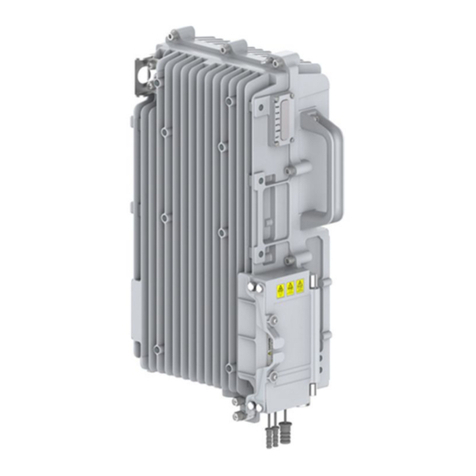
Infinite SCOM-100 Operating instructions

1. Introduction
SCOM-100 is a controller unit for alarm annunciation and remote control using SMS.
The main unit incorporates a Quad Band (850/900/1800/1900MHz) GSM modem, 2
analog inputs, 4 digital inputs, 4 power relay outputs (250V/10A) and a serial RS-232
port. Front panel LED indicators monitor control and digital I/O states.
This step by step troubleshooting guide intends to to provide a general idea of
SCOM's SMS handling and troubleshooting, based on a verification method, quickly
and easily.
What you need:
•An SCOM100.
•An appropriate power supply to power the unit. Minimum 12VDC, 0.8A
•A GSM antenna attached to the SCOM100 device.
•A SIM card capable of seding and receiving SMS messages
Since SCOM100 relies on external factors to provide a functional environment such
us the SIM card, the GSM network coverage and quality, this document will try to
illustrate using simple flowcharts all the possible causes.
2. Power issues
Please follow the SCOM100 device manual to wire an appropriate power supply to
power the unit.
For an
SCOM100-12 a 12VDC/0.8A is needed,
for an SCOM100-24 a 24VDC/1A is needed,
After power up the SCOM100 unit will perform a test procedure. Front panel LEDs
conditions indicating a normal operation should be as follows.
SCOM100
Remote control and alarming
SCOM100: Troubleshooting
Vers. 1.0-1.1.5 – October 2012
Power LED: ON
Network LED:blinking
Status LED: ON
Ready LED: ON

SCOM100
Remote control and alarming
SCOM100: Troubleshooting 2
Possible malfunctions and possible solutions,
Status Possible reasons
Check procedure Check list for SCOM
If the device is powered by a battery it might be depleted or disconnected. If the
device is powered by a UPS the AC mains might not be connected or there might be
blown fuse. If the device is powered by a power supply connected to the AC mains
there might be a blown fuse or a mains failure.
Power LED: OFF - No direct power supply
- No power supply from UPS
- Unit failure
power/UPS/battery
(check presence on VACC and
GND)
Call support
- Check main source power supply
- Check charging of UPS
- Visual inspection of unit
Call support

SCOM100
Remote control and alarming
SCOM100: Troubleshooting 3
2.2 GSM Network operation verification
After power up the SCOM100 unit will perform a test procedure. Front panel LEDs
conditions indicating a normal operation should be as follows.
Possible malfunctions and possible solutions,
Status: Possible reasons:
Check procedure: Check list for SCOM:
Network LED: OFF or
steady ON - No GSM signal
- Unit is not registered in network
- Unit failure
GSM network
(check network using GSM
mobile next to SCOM)
Call support
- Bad signal check with a mobile phone
- Check antenna and connections
- Power cycle the unit to reregister on
the network
Call support
Power LED: ON
Network LED:blinking
Status LED: ON
Ready LED: ON

SCOM100
Remote control and alarming
SCOM100: Troubleshooting 4
2.3 Easy startup sending/receiving SMS messages
2.3.1 Preparing a SIM card
Before installing the SIM card, use your phone to:
1. Clear the PIN code (no PIN needed).
2. Enter your name and phone number in the first place of the phonebook directory of the SIM card.
Note: You can alternatively power up the unit without a SIM card and set the PIN number using a terminal
program on a PC, or you can set a PIN in later configuration stages.
2.3.2 Installing the SIM card
Note: Always remove or install the SIM card, having the unit powered down!
Slide the card tray out by pressing the cardholder’s button with a spiky object such
as a pencil or screwdriver.
Insert the card into the tray and slide the tray with the card faced down into the
cardholder.
3.3 First power up & factory settings
Power up the unit and hold the startup button pressed until the ready LED starts
blinking rapidly.
The unit executes the startup procedure setting all parameters to the factory
defaults, reads the SIM card’s phonebook entry, enters the RUN (Control) mode and
sends a HELLO SMS message to the mobile phone number that was found in the
SIM phonebook entry.
LED indication states are:
1. READY LED will switch on indicating the successful reading of the SIM card’s phonebook entry.
2. STATUS LED will switch on indicating the RUN (Control) mode.
3. NETWORK LED will be blinking to state successful connection to the GSM provider’s network.
The device is now ready to send alarms and information via SMS and and also receive SMS commands.

SCOM100
Remote control and alarming
SCOM100: Troubleshooting 5
For example, if you sent an SMS with the command 1001,0,1 this will result to
change DO1 from 0 to 1.
In order to visually test the receipt of SMS commands from the devices, when
sending an SMS to an SCOM if the operator has a close look at the device, he will
notice that S/R LED will blink for 2 seconds when the SMS is received.
Similarly when the device sends an SMS the S/R LED will also blink for 2 seconds.

SCOM100
Remote control and alarming
SCOM100: Troubleshooting 6
3. Status LED indications
1: Power indicator: Turns on after power up.
2: Four LEDs indicating the digital output states.
3: Turns on while sending or receiving an SMS.
4: Turns on if an error occurs during operation. See sections 9.4 and 9.5 for details.
5: Monitors the device status (RUN/ MONITOR/ STOP). See sections 6.1 and 9.5 for details.
6. Flashes during device start up. Remains on if the device is ready for operation. Turns off if one or more
operating conditions fail. See section 9.5 for details.
7. Flashes if a connection to the GSM provider is established.
8. Four LEDs indicating the digital input states.
LED Indication
POWER Presence of power supply voltage
NETWORK Blinking upon successful registration the GSM provider’s
network
S/R SMS Turns on during SMS receive or transmit
ERROR •Turns on after start up:
SIM card error
Modem error
Missing I/O expansion module
Excessive EM noise or hardware error
•Turns on during operation
Modem error
Excessive EM noise or hardware error
STATUS ON: RUN (Control) state
Blink: MONITOR state
OFF: STOP state

SCOM100
Remote control and alarming
SCOM100: Troubleshooting 7
LED Indication
READY Blinking slowly: The unit starts up after power up (approx.
1 minute)
Blinking fast: The unit starts after holding the start up
button pressed during power up: Initialization process
(approx. 1 minute)
On: Unit start up completed OK
Off with ERROR LED off: No user administrator
found in SIM
Off with ERROR LED on: See ERROR LED
3.1 Quick Troubleshooting
The ready LED
goes off after the
start up sequence.
Case 1: Error LED is off
You started the unit for the first time and the
SIM card does not contain a user name and
phone number in the phone book directory.
See chapter 3.1.
Case 2: Error LED is on
An error occurred during start up.
See manual chapter 9.4 & 9.5.
The unit does not
respond to SMS at
all.
The unit does not register to the GSM
provider network. Check if the ‘NETWORK’
LED is blinking. Connect a proper GSM
antenna to the unit (See Manual chapter 2.6)
The unit does not
respond to
configuration SMS
commands.
The ‘Response SMS’ parameter is probably
off. Set the parameter to on state.
Read Manual chapter 6.2.1
The unit does not
execute my digital
output control
commands.
Check the status LED.
The unit is probably in STOP or MONITOR
status. Set the unit status to RUN. See
Manual chapter 6.1.
Read the SMS response to your command.
The unit does not
send an alarm SMS
after a digital input
state changes.
The device is in STOP mode.
The respective input is not activated for
alarming. Activate the input by sending the
proper configuration command (See Manual
chapter 4.3).

SCOM100
Remote control and alarming
SCOM100: Troubleshooting 8
The analog value
readings through
the monitoring
command seem not
to be correct.
Check sensor cabling for the corresponding
channel (see chapter 2.4)
Set the correct analog channel measurement
parameters (see Manual 4.5.1).
Alarm SMS of an
analog input come
too frequently.
Set a higher alarm delay or a deadband value
for the analog inputs (see Manual 4.5.4)
Other manuals for SCOM-100
1
Table of contents
Popular Remote Control manuals by other brands
SOMFY
SOMFY CENTRALIS RECEIVER Installation and operating instructions

LG
LG AN-MR18BA owner's manual
Harman Kardon
Harman Kardon Harman/kardon HK3490 Remote control guide
RADEMACHER
RADEMACHER Fernotron Programming Centre operating instructions

URC
URC Complete Control MX-880 owner's manual

SILYNX
SILYNX KEY FOB PTT user guide
