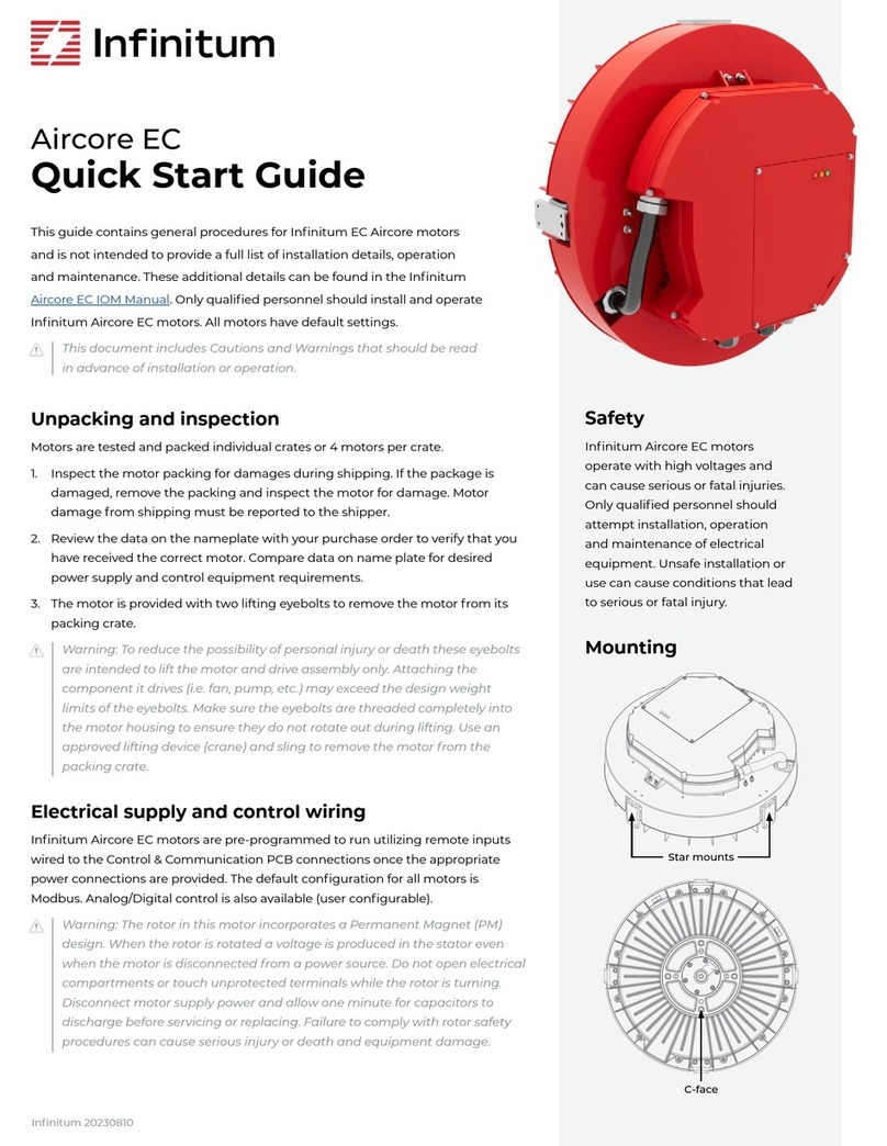
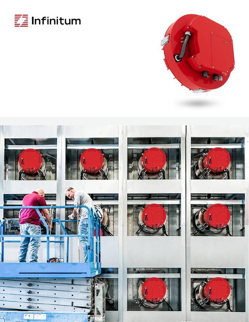
Infinitum Aircore EC Instruction manual

1
Aircore EC
Installation, Operation
& Maintenance Manual
10% More efficient
50% Smaller and lighter
66% Less copper

2
Table of Contents
About the Manual...................................................................................................................................................................... 3
Warnings, Cautions and Notes.......................................................................................................................................................................... 3
Safety Guidelines....................................................................................................................................................................... 3
Electrical ........................................................................................................................................................................................................................... 3
Mechanical......................................................................................................................................................................................................................4
Operating Environment ........................................................................................................................................................................................4
Motor Technology ..................................................................................................................................................................... 5
Motor Overview............................................................................................................................................................................................................ 5
Standard Motor Technology....................................................................................................................................................................... 5
Infinitum Aircore EC Stator......................................................................................................................................................................... 5
Aircore EC Motor Components................................................................................................................................................................. 5
Receiving Inspection................................................................................................................................................................ 6
Packing Inspection....................................................................................................................................................................................................6
Remove Motor from Container.........................................................................................................................................................................6
Compare Name Plate Data .................................................................................................................................................................................6
Rotate Motor Output Shaft..................................................................................................................................................................................6
Ready Spare Storage................................................................................................................................................................................................6
Sealed Motor Bearings...................................................................................................................................................................................6
Scheduled Output Shaft Rotation .........................................................................................................................................................7
Storage Area Recommendations ...........................................................................................................................................................7
Motor Installation ...................................................................................................................................................................... 7
Preparation .....................................................................................................................................................................................................................7
Motor Location .............................................................................................................................................................................................................7
Operating Ambient Temperature ..........................................................................................................................................................7
Motor Mounting and Alignment .....................................................................................................................................................................8
Mounting Options.............................................................................................................................................................................................8
Mounting and Aligning Motor................................................................................................................................................................10
Connecting Motor....................................................................................................................................................................................................10
Control & Communication PCB Connections ............................................................................................................................... 11
AC Main Input PCB Connections........................................................................................................................................................... 11
Circuit Breaker and Wire Sizing...................................................................................................................................................................... 12
Minimum Motor Connection Requirements ........................................................................................................................................ 13
Motor Ground Circuit Verification................................................................................................................................................................. 13
Check Motor Rotation ...........................................................................................................................................................................................14
Connect Motor to Equipment Drive............................................................................................................................................................14
Motor Operation/Bench Test Procedure..........................................................................................................................15
Preparation ................................................................................................................................................................................................................... 15
Motor Drive and Software Setup.................................................................................................................................................................... 15
Introduction to Motor Operation................................................................................................................................................................... 15
Control Interfaces..................................................................................................................................................................................................... 15
Motor Control Desktop Software........................................................................................................................................16
Preparation ................................................................................................................................................................................................................... 16
Connection GUI..........................................................................................................................................................................................................18
Motor Maintenance ................................................................................................................................................................22
Quarterly Maintenance.........................................................................................................................................................................................22
Maintenance Tasks..................................................................................................................................................................................................22
Mechanical....................................................................................................................................................................................................................23
Motor Drive Parameters and Data Type..........................................................................................................................23

3
About the Manual
Warnings, Cautions and Notes
Warnings Cautions and Notes are throughout the manual to alert the technician of potential hazard or
process information. Below is an explanation of the use.
Warnings are posted in bold red and are safety related. Serious injury, death and equipment damage can
result if the instructions in the warning are not followed.
Cautions are posted in bold orange and apply to conditions that can cause equipment damage. If
instructions in the Caution are not followed, motor and associated equipment damage may occur.
Notes: The text of the note is not in bold print. Notes add information that can aid in the completion of a
process or step.
Safety Guidelines
Electrical
Below are electrical safety warnings that are contained in this manual. Each warning is posted in the
applicable step. Warnings are created in bold red to increase visibility. Failure to comply with any warning
can result in serious injury, or death and equipment damage.
Warning: The motor must be installed and connected in accordance with all applicable codes and industry
standard practices. Only qualified technicians should install an electrical motor. Failure to comply with
connection standards can result in serious injury or death and equipment damage.
Warning: The rotor in this motor incorporates a Permanent Magnet (PM) design. When the rotor is rotated
a voltage is produced in the stator even when the motor is disconnected from a power source. Do not
open electrical compartments or touch unprotected terminals while the rotor is turning. Disconnect motor
supply power and allow five minutes for capacitors to discharge before servicing or replacing. Failure to
comply with rotor safety procedures can cause serious injury or death and equipment damage.
Warning: The rotor in this motor incorporates a Permanent Magnet (PM) design. When the rotor is rotated
in a disconnected motor voltage is produced. Once Power is secured, do not allow connected equipment
to turn the rotor. Failure to comply with rotor safety procedures can cause serious injury or death and
equipment damage.
Warning: When the rotor is removed from the motor housing the permanent magnets can expose
surrounding personnel and equipment to powerful magnetic fields. This can cause serious health hazards
to persons with pacemakers, hearing aids or other implanted electronic devices. The magnetism may
impact mobile phones and credit cards.
Warning: To reduce the possibility of personal injury or death and equipment damage, always make sure
wire connections are secure and wires are in the correct location.
Warning: Always Tagout and Lockout the electrical motor circuit and practice all company safety
procedures when installing, troubleshooting, or repairing a motor. Always verify power is secured with a
multimeter prior to work. Failure to adhere to Tagout/Lockout and industry standard practices can result in
serious personal injury or death and equipment damage.

4
Safety Guidelines Continued
Warning: Motors must be properly grounded. Adhere to NEC and all State/Local guidelines when installing
the motor ground circuit. Failure to ground a motor can cause personal injury or death and equipment
damage.
Warning: Electrical power must be secured for five minutes to allow capacitors to discharge before
removing the control unit cover. Capacitor discharge can cause personal injury and equipment damage.
Mechanical
These motors are well suited for a wide range of applications. Follow all mechanical safety requirements
issued by the associated equipment manufacturer.
Warning: After troubleshooting, repairing, or installing this motor, make sure that all tools and debris are
removed from the motor and surrounding area. Tools or debris that contact the rotating shaft can cause
serious injury or death and equipment damage.
Warning: Never operate the motor when the safety cover is removed. Always observe rotating equipment
safety. No loose clothing, pin back hair and no jewelry. Failure to comply with rotating equipment safety can
cause serious injury or death and equipment damage.
Warning: Only Factory Authorized Representatives are authorized to disassemble this motor. Disassembly
practices must adhere to national/local codes and industry standard practices. Strong magnetic fields
emitted by permanent magnets can cause serious injury or death to personnel with electronic implants
and damage electronic equipment.
Warning: The motor is provided with lifting lugs. The lugs are intended to lift the motor assembly only.
Attaching the component it drives will exceed the design weight limits. To reduce the possibility of personal
injury or death and equipment lift the motor only, make sure the lugs are completely threaded into the
motor, and ensure they do not rotate out during lifting.
Warning: To reduce the possibility of personal injury and equipment damage, only use a lifting device and
straps that are rated for the motor weight. Always inspect straps for damage and weight certification prior
to use.
Operating Environment
Environmental safety describes the environment the motor is authorized to be operated in. Never operate
this motor in an unauthorized environment.
Warning: This motor is not certified to operate in any hazardous environments. Operating a motor in areas
contaminated with explosive gases can cause explosions resulting in serious injury or death and equipment
damage.

5
Motor Technology
Motor Overview
Infinitum has created a new generation of electric motors with unparalleled efficiency and durability. We’ve
reinvented axial air-core motors using lightweight materials and a modular design that generates the same
power with less weight than a legacy motor. These motors are manufactured at a fraction of the carbon
footprint created by conventional motors
Standard Motor Technology
The introduction of the Aircore EC motor surpasses motors utilizing standard technology and construction.
Like all motors Infinitum machines have a stator, the stationary part and a rotor, the rotating component
Aircore EC motors have two rotors. In traditional motors the stator is located in the body of the motor
and is usually made of iron cores with copper windings. This iron and copper adds to the overall weight
of the motor. Additionally, the insulation on these coil windings degrades with heat and time requiring
maintenance or eventual replacement of the motor.
Infinitum Aircore EC Stator
The Aircore EC stator is a Printed Circuit Board (PCB)
rather than utilizing a heavy iron core and with copper
windings. The Infinitum motor is an axial designed
machine with the PCB stator sandwiched between two
rotors. Permanent magnets are attached to the surface
of the two rotors. The magnetic flux in this motor goes
through the PCB stator from one rotor to the other
with no iron the flux path. Since there is no iron in the
magnetic path, the motors can be classified as an air-
core design.
Aircore EC Motor Components
The PCB stator design allows for a smaller motor that weighs significantly less than a conventional motor.
Key components are identified by the drawing below.

6
Receiving Inspection
Review and complete all appropriate sections prior to motor installation. The motor is shipped in a robust
container. The container and motor can be moved by using a dolly, pallet jack or fork truck.
Packing Inspection
It is recommended to perform the below listed inspections once the motor is located in a clean, dry area.
Inspect the motor packing for damages during shipping. If the package is damaged, remove the packing
and inspect the motor for damage. Motor damage from shipping must be reported to shipper.
Remove Motor from Container
Warning: The motor is provided with lifting lugs. The lugs are intended to lift the motor assembly only.
Attaching the component it drives will exceed the design weight limits. To reduce the possibility of personal
injury or death and equipment lift the motor only, make sure the lugs are completely threaded into the
motor, and ensure they do not rotate out during lifting.
Warning: To reduce the possibility of personal injury and equipment damage, only use a lifting device and
straps that are rated for the motor weight. Always inspect straps for damages and weight certification prior
to use.
Remove top of the packing crate and install the supplied lifting lugs. Make sure the lugs are threaded
completely into the motor housing. Remove hardware securing motor to packing crate. Use an approved
lifting device and sling to remove the motor from the packing crate.
Compare Name Plate Data
Compare data on name plate with purchase order to verify receipt of proper motor. Compare data on name
plate for desired power supply and control equipment requirements.
Rotate Motor Output Shaft
Warning: The rotor in this motor incorporates a Permanent Magnet (PM) design. When the rotor is rotated
a voltage is produced in the stator even when the motor is disconnected from a power source. Do not
open electrical compartments or touch unprotected terminals while the rotor is turning. Disconnect motor
supply power and allow five minutes for capacitors to discharge before servicing or replacing. Failure to
comply with rotor safety procedures can cause serious injury or death and equipment damage.
Make sure all motor wire connections are properly terminated and insulated. Turn the motor rotor (output
shaft) by hand. It should turn freely with some drag from the bearing seals.
Ready Spare Storage
Motors purchased for ready spares are not placed into service immediately. These motors should be stored
in a clean, dry space. Avoid spaces with large temperature swings because they produce condensation.
Cover motors to prevent airborne dust and dirt particles. If storage area is prone to vibration, place vibration
dampers under motor base to prevent premature wear and damage to bearings.
Sealed Motor Bearings
The bearings used in this motor are lubricated and sealed at the factory. The motor does not require
lubrication in the field or during storage.

7
Receiving Inspection Continued
Scheduled Output Shaft Rotation
Warning: The rotor in this motor incorporates a Permanent Magnet (PM) design. When the rotor is rotated
a voltage is produced in the stator even when the motor is disconnected from a power source. Do not
open electrical compartments or touch unprotected terminals while the rotor is turning. Disconnect motor
supply power and allow five minutes for capacitors to discharge before servicing or replacing. Failure to
comply with rotor safety procedures can cause serious injury or death and equipment damage.
It is recommended the rotor (output shaft) be rotated five to ten times per every quarter (three months).
This distributes grease in the bearings and reduces the chance of corrosion formation on bearing rolling
elements and raceways. Bearing seals can add some resistance to turning the rotor.
Storage Area Recommendations
A dry storage space without large temperature changes is recommended for motor storage.
Motor Installation
Preparation
Review this entire manual prior to scheduling the motor installation. All equipment related to systems
operation must be secured and have an active Tagout/Lockout procedure in accordance with company
safety policies. All users of should be notified of equipment outage.
Motor Location
Warning: This motor is not certified to operate in any hazardous environments. Operating a motor in areas
contaminated with explosive gases can cause explosions resulting in serious injury or death and equipment
damage.
Electric motors have guidelines for the location and operating environment. These guidelines are listed
below:
• The motor should be located in a ventilated enclosure and should be in an area that allows air circulation.
• Air cooling inlets and outlets must not be obstructed.
• The enclosure cannot be located in an area with harmful or explosive gasses.
• The area should be free from dust and metallic particles.
• The motor should be easily accessed for cleaning and maintenance.
The motors are intended for indoor applications and can also be located in outdoor enclosures that protect
them from weather exposure.
Operating Ambient Temperature
The ambient temperature of the air supplied to the motor cooling inlet should not exceed 40° C (104° F) or
be less than -25° C (-13° F). Consult Infinitum for ambient temperatures not within the requirements.

8
Receiving Inspection Continued
Motor Mounting and Alignment
The Aircore EC motor system is supplied with an integrated electronic drive. The motor and drive housing
are the major components of the assembly.
Refer to motor datasheets for detailed dimension drawings.
Mounting Options
Driven equipment (for example, a fan wheel) should be mounted to the shaft using as much of the available
shaft length as possible. A shaft keyway and shaft key are provided for secure coupling of hubs to the shaft.
There are two mounting options for the motor. Either the faceplate or mounting blocks on the outside
edges of the motor may be used to mount the motor.
Peripheral mounting block option: There are four mounting blocks on the surface of the motor, spaced at
90º intervals. Each block has provisions for a lifting lug that can be used to lift the motor, and mounting
holes at the drive end (DE) face and transverse surface.
The transverse face of the mounting block has threaded holes for four mounting bolts. All four mounting
bolts should be installed for secure motor mounting. See the below diagram for a typical mounting hole
pattern. Specific motor drawings should be used for exact dimensions.

9
Motor Installation Continued
Faceplate mounting: Infinitum Aircore EC motors are not a NEMA standard frame size but utilize a NEMA
182TC faceplate mounting configuration.
The DE face of the mounting block has threaded holes for four bolts (M8X1.25). All bolt holes should be used
for secure mounting of the motor to equipment.
Caution: Use care when installing the driven equipment onto the rotor shaft. Do not force the hub or
coupling onto the shaft since this may damage the motor bearings. If the hub or coupling does not slide
without resistance, check alignment of the equipment with the rotor shaft.
Maintain adequate clearance between the front of the motor body and the equipment to prevent
mechanical obstruction that may cause damage or injury.
The motor and stator assembly must be mounted on a structure that will support the operational weight
of the motor. Use vibration dampers at motor assembly mounts to reduce motor vibration. Align the stator
output shaft centerline with the driven component and install mounting hardware but do not tighten. This
is completed with the alignment process.

10
Motor Installation Continued
Mounting and Aligning Motor
Warning: The motor is provided with lifting lugs. The lugs are intended to lift the motor assembly only.
Attaching the component it drives will exceed the design weight limits. To reduce the possibility of personal
injury or death lift the motor only and make sure the lugs are completely threaded into the motor.
Warning: To reduce the possibility of personal injury and equipment damage, only use a lifting device and
straps that are rated for motor weight. Always inspect straps for damage and weight certification prior to
use.
Warning: Always Tagout and lockout the electrical motor circuit and practice all company safety
procedures when installing, troubleshooting, or repairing a motor. Always verify power is secured with a
multimeter prior to work. Failure to adhere to Tagout/Lock and industry standard practices can result in
serious personal injury or death and equipment damage.
Warning: The rotor in this motor incorporates a Permanent Magnet (PM) design. When the rotor is rotated
in a disconnected motor voltage is produced. Do not open any of the compartments or touch unprotected
terminals while the rotor is turning. Disconnect motor supply power and allow five minutes for capacitors
to discharge before servicing or replacing. Failure to comply with rotor safety procedures can cause serious
injury or death and equipment damage.
Caution: Use care when installing the driven equipment onto the rotor shaft. Do not force the hub or
coupling onto the shaft since this may damage the motor bearings. If the hub or coupling does not slide
without resistance, check alignment of the equipment with the rotor shaft.
The motor may be directly mounted to equipment such as fan wheels or may be connected through
a belt or pulley system. It may also be attached through a shaft coupling, e.g., to an independently
mounted pump, or to a torque meter in a laboratory setting. Ensure proper alignment is maintained in all
arrangements.
Use driven equipment manufacturer’s recommendations for aligning the motor with the fan drive or
coupling. Tighten all bolts and nuts on the motor mount.
Motor rotation must be verified after electrical connection. Incorrect rotation can damage equipment.
Connecting Motor
Each of the circuit cards and housing components has a separate design function. Only two of the circuit
boards have user inputs. The main circuit boards and connection points are highlighted below:
1. Grounding Terminal - Connector for supply
return wire
2. AC Input and Rectifier PCB - Connections for
three-phase supply. Rectifiers convert AC to DC
for internal use
3. Inverter PCB - Inverter converts DC to AC for
internal use. No user connections exist for this
circuit card
4. Control and Communications PCB - This
circuit card contains advanced controls and
communications

11
Motor Installation Continued
Control & Communication PCB Connections
1. Relay (1) – NO/NC (COM must be used).
2. Digital Input (4) – DIN1, DIN2, DIN3 & DIN4
3. Digital Output (2) – D01 & DO2
4. Auxiliary Voltage (1) – +24v (GND must be
used) (Do not exceed 24V on this input)
5. Analog Output (1) – A_OUT (GND must be
used)
6. Analog Input (1) – A_IN (GND must be used)
7. EIA-485 Interface (1) – 485_P & 485_N (GND
must be used)
8. Modbus termination
9. RJ45 for GUI connection
Terminals on the interface board feature push-
button spring clips. The push-button on each
terminal must be depressed while inserting the
wire. Releasing the push-button clips the wire
into place.
AC Main Input PCB Connections
The AC Main Input PCB is the circuit card responsible
for distribution 3-phase supply voltage and
converting AC to DC for internal use.
The supply voltage connections are:
1. Supply Voltage Phase A
2. Supply Voltage Phase B
3. Supply Voltage Phase C
The AC input terminals feature spring clips. The
orange tab must be raised to insert the wire.
Releasing the orange tab clips the wire into place.

12
Motor Installation Continued
Conductor Size and Terminal Data
Board Terminals
Maximum
Conductor Size Exposed
Conductor
Length
Terminal Type
mm^2 AWG
Control and
Command Board Control Terminals 1.3 16 8 mm Spring Terminal
AC Main Input Board AC Mains-U, V & W 5.2/3.3 10/12 12 mm Spring Terminal
Screw Earth Ground 1.6 14 12 mm Lug and Screw.
Max torque 2 Nm.
Inverter No User Connections NA NA NA NA
Inductor No User Connections NA NA NA NA
Circuit Breaker and Wire Sizing
Fuses or breakers should be used to provide protection for the input power cables. These should be installed
in the incoming supply lines according to the table below. UL listed non-time-delay type T or RK1 fuses are
recommended. Type B circuit breakers of equivalent rating to the fuses may be used. Other fuse or breaker
types may be acceptable. Fuses and breakers should comply with any local codes or regulations.
The input wiring should be sized based on the current requirements of the motor. The connector minimum
and maximum wire sizes are included in Table 2
The maximum permissible short circuit current at the drive input power terminals is 5kA
Table 1: Breakers and Fuses (3-phase 480V AC (+/- 10%) - 3 Phase 460V Output)
Power (HP) Rated
Current (A)
UL Fuses
(Class T or RK1)
or UL Type B Breakers
Minimum Suggested
Wire Size (AWG)
56.0 10 16
7.5 9.0 15 16
10 12.0 15 14
15 20.0 25 12
Table 2: Terminal Connection Data
min. max.
Rigid cable cross-section 0.2 mm² 6 mm²
Flexible cable cross-section 0.2 mm² 6 mm²
Cross section AWG 24 10
Wire-end ferrules (w/insulating collar) 0.2 mm² 4 mm²

13
Minimum Motor Connection Requirements
Warning: Always Tagout and lockout the electrical motor circuit and practice all company safety
procedures when installing, troubleshooting, or repairing a motor. Always verify power is secured with a
multimeter prior to work. Failure to adhere to Tagout/Lock and industry standard practices can result in
serious personal injury or death and equipment damage.
Warning: The rotor in this motor incorporates a Permanent Magnet (PM) design. When the rotor is
rotated in a disconnected motor voltage is produced. Do not open any of the pods or touch unprotected
terminals while the rotor is turning. Disconnect motor supply power and allow five minutes for capacitors
to discharge before servicing or replacing. Failure to comply with rotor safety procedures can cause serious
injury or death and equipment damage.
Warning: To reduce the possibility of personal injury or death and equipment damage, always make sure
wire connections are secure and wires are in the correct location.
Caution: To prevent the possibility of motor damage, always use terminating ferrules for all supply wires.
Terminating ferrules create a single connection point that is not available with multiple conductor wires.
Wire tensile forces can affect the point of termination during installation and motor operation. Terminal
blocks with the correct wiring installed ensure safe motor operation. Using the correct wire gauge and
amount of exposed conductor length with ferrules installed on each wire satisfies the requirements.
Make sure the source of power to all supply wires has had Tagout/Lockout procedures performed in
accordance with company safety guidelines.
Strip wires and crimp on wire ferrules. Install each wire into the appropriate terminal block as provided in
the wiring instructions. Verify all connections are tight and installed to specifications.
Motor Ground Circuit Verification
Warning: Motors must be properly grounded. Adhere to NEC and all State/Local guidelines when installing
the motor ground circuit. Failure to ground a motor can cause personal injury, death, and equipment
damage.
It is advised to conduct resistance readings with a multimeter on the motor ground circuit. Never initiate a
startup on a motor that does not have a complete ground circuit.
Motor Installation Continued

14
Check Motor Rotation
Warning: Never operate the motor when the safety cover is removed. Always observe rotating equipment
safety. No loose clothing, pin back hair and no jewelry. Failure to comply with rotating equipment safety can
cause serious injury or death and equipment damage.
Note: If the motor has been tested and the technician has verified motor rotation prior to installation, the
facility can elect not to perform this test because of redundancy.
Prerequisites: The motor has been installed, aligned and electrically connected. The fan belt is removed, or
coupling is disconnected. The motor must be briefly energized to check for proper rotation.
Steps are outlined below:
1. Review all installation instructions and all warnings prior to testing the motor.
2. Remove electrical lockout/Tagout.
3. Follow all safety precautions and energize the motor briefly to determine rotation. If the motor rotates
opposite of intended direction, switch the direction command.
4. Perform electrical Tagout/lockout steps for the circuit.
Connect Motor to Equipment Drive
Warning: Always Tagout and lockout the electrical motor circuit and practice all company safety
procedures when installing, troubleshooting, or repairing a motor. Always verify power is secured with a
multimeter prior to work. Failure to adhere to Tagout/Lock and industry standard practices can result in
serious personal injury or death and equipment damage.
Prerequisite: Motor rotation has been verified. The final series of steps will place the load on the motor and
test system operation.
Steps outlined below:
1. Make sure Tagout/Lockout procedures have been performed.
2. Install coupling and verify alignment or install the belt and verify alignment for pulley systems.
3. Install all safety covers and clear Tagout/Lockout.
4. Start the system and verify the motor operates properly.
Motor Installation Continued

15
Motor Operation/Bench Test Procedure
Preparation
This procedure is designed to describe the connection and interface with motor software for testing. The
motor must be securely mounted and all safety and shop procedures followed the associated test bench.
All wiring and connection standards contained in the installation procedure must be adhered to for the test
setup.
1 2
4 6
Motor Drive and Software Setup
1. Remove the access panel on the drive cover.
2. The below image shows the access panel
removed.
3. Connect the 3-phase AC mains 460VAC input
wires to the input terminals as shown below.
Press down firmly on the orange tabs to
secure the leads.
4. Connect the grounding cable to the marked
Ground Lug.
5. Install the provided MotorControl software on
a Windows PC.
6. Connect your PC to the RJ-45 terminal in the
drive using an Ethernet cable.
7. Refer to Motor Control Desktop Software
section for complete software instructions.
Introduction to Motor Operation
Operating the motor requires three control types:
• Start/Stop commands
• Commanding the direction of rotation
• Commanding the speed of rotation
Control Interfaces
The Infinitum IEs motor system provides the following
interfaces that allow a user to control the motor:
• A Windows-based desktop GUI
• Digital and analog inputs
• Modbus TCP or RTU protocols
Start/stop behavior can be controlled by the following
methods:
• Using the GUI
• Sending Modbus commands
• Using digital inputs
Motor direction can be controlled by the following
methods:
• Using the GUI
• Sending Modbus commands
• Using digital inputs to operate in forward/reverse
• Setting the default to the required direction
Motor speed can be controlled by the following
methods:
• Using the GUI
• Sending Modbus commands
• Using digital inputs to activate pre-defined speed set
points
• Using analog input to operate over a scaled speed
range
The motor control software allows the user the ability
to utilize the advanced functions of the Infinitum IES
motor.

16
Motor Control Desktop Software
Preparation
Motor Installation & Connection
Warning: Always Tagout and lockout the electrical motor circuit and practice all company safety
procedures when installing, troubleshooting, or repairing a motor. Always verify power is secured with a
multimeter prior to work. Failure to adhere to Tagout/Lock and industry standard practices can result in
serious personal injury or death and equipment damage.
TCP and Serial are the two connection protocols. TCP utilizes a RJ45 connector (1) and Serial connections are
completed at the terminal board (2). Serial connections are not available at this time.
Complete the following preparation steps:
1. The motor must be installed onto an approved test
bench or installed into the equipment it serves. Go
to Motor Installation and complete all installation
steps.
2. Verify RJ45 female connector is connected to
CAT 5, CAT 5e, CAT 6, CAT 6A or CAT 7 cable. Use
connector (9) on the communication card.
3. Remove existing tagout and lockout equipment
and energize motor.
Set Static IP Address (Windows 10 Professional)
All computers that communicate with an Infinitum
IES Motor must have a static IP Address set up.
This completes the communication link for
the computer to the Motor Control Software.
If the correct static IP address is not setup
the computer will not communicate with the
motor.
Note: Screen shots may change slightly
depending on the version of Windows installed
on the computer. The concept is the same with
all versions. Windows 10 Professional is the
operating system shown.
1. Left click Start Button on bottom tool bar.
2. Quick Access menu appears, left click
Settings icon).

17
The Windows Settings screen opens.
1. Left click the Network & Internet icon.
The Network Status screen opens.
2. Left click the Ethernet Icon.
The Network and Sharing Screen opens.
3. Left click on the Ethernet Icon.
An Ethernet Status screen opens.
4. Left click on the Properties button.
Ethernet Properties screen opens.
5. Left click Internet protocol Version 4.
The selection is highlighted.
6. Click the Properties button.
The Internet Protocol Version 4 (TCP/IPv4) screen opens.
The default selection is Obtain an IP address automatically.
7. Left click Use the following IP address.
8. Enter 172.17.20.153 into the IP address.
9. Enter 255.255.0.0 into the Subnet mask.
10. Left click the OK button.
11. Close all windows opened when setting the static IP
address.
The default selection of Obtain an IP address automatically
must be selected if computer functionality from Ethernet
connection is desired in future.
Motor Control Desktop Software Continued
2
3
4
5
6
7
8
9
10

18
Motor Control Desktop Software Continued
Connection GUI
Install Software
Install the provided Motor Drive Control software onto a laptop, or desktop computer. This computer must
be Windows based. The latest software and download instructions are found on the Infinitum Support
page. There is a SW Installer on the support page. Follow the instructions in the Installer. This website
location is protected, so an Infinitum login is required to access.
To run the Motor Drive Control Software on a Windows computer, you will need to install Windows x86 .NET
Core SDK v3.1.423.
This SDK can be found here.
After installing the SDK, restart your computer for the installation changes to take effect.
The Motor Drive Control Software is installed on the laptop or computer: C:\Program Files (x86)\Infinitum-
MotorControlGUI. The installer also creates a shortcut to the software on the desktop of the computer.
The connection for the GUI between a laptop/PC can be configured to use TCP (Ethernet) or Serial.
Connection to Motor (Ethernet)
Connect a standard ethernet cable from the laptop/PC to the motor. This computer requires the static IP
address mentioned above. The ethernet connection on the Infinitum motor is on the CIM card, accessible
when the VFD access port or VFD cover is removed (depends on version of the VFD).
Connection to Motor (Serial)
Connect a serial cable from the laptop/PC to the motor. The serial connection on the Infinitum motor is
on the CIM card, accessible when the VFD access port or VFD cover is removed (depends on version of the
VFD). The Serial connections are identified as 485_P, 485_N, and GND on the CIM silkscreen by the access
port. Polarity must be maintained from the VFD access port to the computer.
Powering on the Motor
The Motor Drive Control software needs to “Connect” to the motor for control. This connection is a two-way
handshake between the application running on the computer and the firmware running in the motor VFD.
The Connection Protocol is a pull-down option in the upper left of the Motor Drive Control Software. For an
ethernet connection (default) the protocol should be TCP. This connection can be changed to “Serial” if a
serial connection is desired.
If the Motor Drive Control software is running on the computer, the connection with the motor will be
established when the motor is powered on. The “Status: will go from “Not Connected” to “Connected” once
this connection is established.
If the motor is powered on after the Motor Control software is started, the connection must be established
manually. To establish this connection, use the Connect button in the upper left of the GUI as shown in the
image below.

19
Motor Control Desktop Software Continued
Once the motor is connected to the computer, the “Status” in the upper left box should indicate
“Connected” in green text as indicated in the next photo.
Once “Connected”, the connect button changes to a red “DISCONNECT” button. This button is used
to break the connection between the GUI and the motor as noted in the image below:

20
Motor Control Desktop Software Continued
While connected, the following data can be set or read by the Motor Drive Control Software for parameters
of the motor. The upper portion of the Motor Drive Control Software window is for real-time motor
information. The lower portion is to set motor parameters.
Real-time motor information: Upper portion of window
• Connection Protocol: TCP or Serial
› Connect or Disconnect: Button to establish or break the communication link with the motor
• Status: Connected or Not connected- Connection status to motor
› IP Address: Address used for ethernet connection
› Continuously Read Registers- Check box for continuous data updates. Uncheck to validate Fail-Over
features
• Start Logging: Real-time data logging. If logging is selected, the Motor Drive Control Software will
prompt a directory to record the log file. The default is the Windows Documents directory. The log file is a
standard Windows Excel file.
• Save State: Saves values of all software parameters in a JSON file
• Motor Control: Allows Speed and Direction control: Set Speed, Actual Speed, RPM range, Motor Direction,
Start/Stop indicator
• Faults: Operational Fault indications
User Information: Lower section of window. Some information below may look slightly different due to
different versions of the Communications Interface Module (CIM) and Inverter board firmware.
• Graphical Readbacks: Displays selected operational parameters in graphical format. X and Y axis values
are user settable. Options include Stator Temperature, Power Output, DC Bus Voltage, Average RMS
Current, and Torque. The graph Period is selectable (30 sec – 1 hr. in 15 min increments)
• Digital Readbacks Displays actual motor operating parameters and fault/warning messages: DC Bus
Voltage (V), Average RMS Current (A), Stator Temp (°C), Power Output (W), and Torque (Nm)
• Analog/Digital Config. Displays values for motor functions including Analog In 1 Function, Analog In 1
Minimum Setting, Analog In 1 Maximum Setting, Analog In 1 Type, Analog Out 1 Function, Analog Out 1
Type, Digital In 1 Function, Digital In 2 Function, Digital In 3 Function, Digital In 4 Function, Digital Out 1
Function, Digital Out 2 Function
• Temperature Sensors: Realtime information on Stator RTD Temp (°C), Inverter Board Temp (°C), Heat Sink
(Internal Case) Temp (°C), CIM Temp (°C)
• Parameter Settings: User configurable options the online parameters for Operating Limits, Operation
Type, Communication Settings, Fault Reset, Terminal Settings, Fail Over Settings. Remember to use the
“Apply” button to save this information in the motor if you change any values. You must use the Apply
button to Enable the Fail Over Settings.
• Parameter Monitor: Displays live information on settings established by the Parameter Setting function.
These include Operating Limits (Motor Max Current (A),Speed Model Minimum (rpm), Speed Model
Maximum (rpm), Max Acceleration, Max Deceleration), Monitor-Electrical (Average RMS Current),
Monitor – Performance (Consumed Power, Drive Run Time, Motor Run Time, Output Torque, Output
Power), Monitor-Operating (Start/Stop Actual, Direction Actual, Speed Actual), Monitor – AI/AO (AI1 Value,
AO1 Value), Monitor – DI/DO (DI1 Value, DI2 Value, DI3 Value, DI4 Value, DO1 Value)
Other manuals for Aircore EC
2
Table of contents
Other Infinitum Engine manuals
Popular Engine manuals by other brands

Volvo Penta
Volvo Penta D25A MS Operator's manual
Nord Drivesystems
Nord Drivesystems B 1000 Operating and maintenance instructions
Allen-Bradley
Allen-Bradley 857 user manual
GEIGER
GEIGER GB45MR Series Original assembly and operating instructions

ULPOWER
ULPOWER UL390i installation manual

Lenze
Lenze MD KS Series operating instructions
Selve
Selve SEE-NHK quick start guide

Hyundai Seasall
Hyundai Seasall D170 Series Installation and operating manual
Siemens
Siemens TC65 user guide
Mitsubishi
Mitsubishi S16R Operation & maintenance manual
Ametek
Ametek dunkermotoren BG 65 dMove Series Translation of the original function and connection guide

BMW
BMW D150W Brochure & specs
