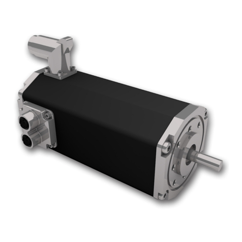
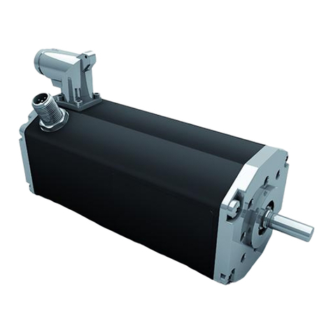
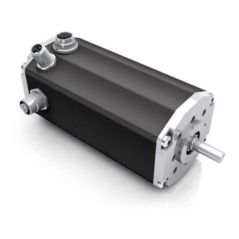
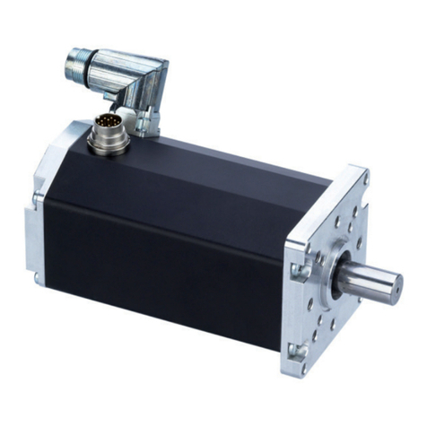
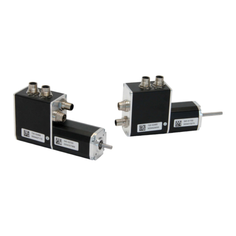
Ametek dunkermotoren BG 65 dMove Series User manual

BG 65 dMove /BG 66 dMove
Typ:
BG 65x25 dMove / BG 66x25 dMove
BG 65x50 dMove / BG 66x50 dMove
BG 65x75 dMove / BG 66x75 dMove
Part No:
88565.14XXX / 88566.14XXX
88565.15XXX / 88566.15XXX
88565.16XXX / 88566.16XXX
Original Funktions- und Anschlussbeschreibung/
Translation of the original function and connection guide

Page/Seite 2 / 54 BG 65 dMove / BG 66 dMove Version 15-02-2023
Inhalt
1. Zu dieser Dokumentation...................... 5
1.1 Haftung und Gewährleistung............................... 6
1.2 Zielgruppe........................................................... 6
1.3 Sicherheitshinweise............................................. 6
1.4 Weitere Piktogramme.......................................... 7
1.5 Gefahrenzeichen ................................................. 7
1.6 EG/EU-Konformitätserklärung ............................. 8
1.7 Richtlinie Niederspannungsrichtlinie
(NSR) 2014/35/EU .............................................. 8
2. Sicherheitshinweise............................... 9
2.1 Bestimmungsgemäße Verwendung..................... 9
2.2 Vorhersehbarer Fehlgebrauch ............................. 9
2.3 Grundlegende Sicherheitshinweise.................... 10
2.4 Sicherheitshinweise für Personal ....................... 10
2.5 Sicherheitshinweise zu Betriebsphasen............. 11
2.5.1 Transport........................................................... 11
2.5.2 Installation ......................................................... 11
2.5.3 Reinigung.......................................................... 11
2.5.4 Wartung/Reparatur............................................ 11
2.5.5 Umweltgerecht entsorgen ................................. 11
2.6 Hinweise auf besondere Gefahrenarten ............ 12
2.6.1 Elektrische Energie/elektromagnetische
Sicherheit .......................................................... 12
2.6.2 Mechanische Sicherheit..................................... 12
3. Transport und Lagerung...................... 13
4. Produktbeschreibung .......................... 14
4.1 Aufbau .............................................................. 14
4.2 Starter Kit.......................................................... 15
4.3 Software Drive Assistant 5 ................................ 15
Content
1. About this Documentation .................... 5
1.1 Liability and Warranty .......................................... 6
1.2 Target Group....................................................... 6
1.3 Safety Notes ....................................................... 6
1.4 Further Icons....................................................... 7
1.5 Hazard Signs ...................................................... 7
1.6 EC/EU Declaration of Conformity ........................ 8
1.7 Directives Low-Voltage Directive
(LVD) 2014/35/EU ............................................... 8
2. Safety Notes ........................................... 9
2.1 Intended Use ...................................................... 9
2.2 Expected Misuse ................................................ 9
2.3 Basic Safety Notes............................................ 10
2.4 Safety Notes for Staff ........................................ 10
2.5 Safety Notes concerning Operating Phases ...... 11
2.5.1 Transport........................................................... 11
2.5.2 Installation ......................................................... 11
2.5.3 Cleaning............................................................ 11
2.5.4 Maintenance/Repair .......................................... 11
2.5.5 Environmentally Compatible Disposal ................ 11
2.6 Notes concerning Special Hazard Types ........... 12
2.6.1 Electrical Energy/Electromagnetic
Safety................................................................ 12
2.6.2 Mechanical Safety ............................................. 12
3. Transport and Storage......................... 13
4. Product Description............................. 14
4.1 Design .............................................................. 14
4.2 Starter Kit.......................................................... 15
4.3 Software Drive Assistant 5 ................................ 15

Version 15-02-2023 BG 65 dMove / BG 66 dMove Page/Seite 3 / 54
4.4 Optionale Anbauten .......................................... 15
4.5 Funktionen........................................................ 16
4.6 Ansteuerungsvariante CANopen dMove CO...... 17
4.7 Ansteuerungsvariante dMove IO........................ 19
4.8 Schutzfunktionen .............................................. 20
4.8.1 Übertemperaturschutz....................................... 20
4.8.2 Unterspannungsabschaltung Logikversorgung .. 20
4.8.3 Unterspannungsabschaltung Leistungs-
versorgung........................................................ 20
4.8.4 Strombegrenzung (I2t)........................................ 21
4.8.5 Ballastschaltung (optional) ................................. 24
4.8.6 Spannungsgeregeltes Bremsen......................... 25
4.8.7 Grenzwerte Schutzfunktionen............................ 25
5. Technische Daten ................................ 26
5.1 Produktspezifikation BG 65 dMove ................... 26
5.2 Produktspezifikation BG 66 dMove ................... 27
5.3 Elektrische Daten .............................................. 28
5.4 Umgebungsbedingungen.................................. 28
5.5 Maßzeichnung BG 65 dMove CO
(mit CAN-Stecker) ............................................. 29
5.6 Maßzeichnung BG 65 dMove IO
(ohne CAN-Stecker) .......................................... 29
5.7 Maßzeichnung BG 66 dMove CO
(mit CAN-Stecker) ............................................. 30
5.8 Maßzeichnung BG 66 dMove IO
(ohne CAN-Stecker) .......................................... 30
5.9 Wellenbelastungsdiagramm .............................. 31
5.10 Typenschild ....................................................... 32
6. Installation ............................................ 33
6.1 Mechanische Montage...................................... 34
6.2 Elektrische Montage.......................................... 35
6.3 EMV-konforme Installation................................. 36
4.4 Optional Attachments ....................................... 15
4.5 Functions.......................................................... 16
4.6 Type of control CANopen dMove CO ................ 17
4.7 Type of control dMove IO .................................. 19
4.8 Protective Functions.......................................... 20
4.8.1 Overtemperature Protection .............................. 20
4.8.2 Undervoltage Switch-Off of the Logic Supply..... 20
4.8.3 Undervoltage Switch-Off of the Power-
Supply............................................................... 20
4.8.4 Current Limitation (I2t) ........................................ 21
4.8.5 Ballast Circuit (optional) ..................................... 24
4.8.6 Voltage Controlled Braking ................................ 25
4.8.7 Thresholds Protection Functions ....................... 25
5. Technical Data...................................... 26
5.1 Product specification BG 65 dMove.................. 26
5.2 Product specification BG 66 dMove.................. 27
5.3 Electrical Data................................................... 28
5.4 Environmental Conditions.................................. 28
5.5 Dimensional Drawing BG 65 dMove CO
(with CAN-connector)........................................ 29
5.6 Dimensional Drawing BG 65 dMove IO
(without CAN-connector)................................... 29
5.7 Dimensional Drawing BG 66 dMove CO
(with CAN-connector)........................................ 30
5.8 Dimensional Drawing BG 66 dMove IO
(without CAN-connector)................................... 30
5.9 Shaft load chart................................................. 31
5.10 Motor label........................................................ 32
6. Installation ............................................ 33
6.1 Mechanical Assembly........................................ 34
6.2 Electrical Assembly ........................................... 35
6.3 EMC compliant installation ................................ 36

Page/Seite 4 / 54 BG 65 dMove / BG 66 dMove Version 15-02-2023
6.4 Schutzleiter ....................................................... 37
6.5 Schutzerdung ................................................... 37
6.6 Leistungs- und Logikversorgung,
Ein- und Ausgänge ........................................... 38
6.6.1 Leistungs- und Logikversorgung, Ein- und
Ausgänge.......................................................... 38
6.6.2 Gegenstecker mit Anschlussleitung................... 41
6.6.3 Motor mit Anschlusskabel verbinden ................. 41
6.7 Leistungs- und Logikversorgung,
Ein- und Ausgänge (legacy)............................... 42
6.7.1 Anschlussleitung mit Dose, 15-polig.................. 44
6.8 CANopen-Feldbusanschluss
(nur für CO Versionen) ....................................... 45
6.8.1 CANopen-Gegenstecker mit Anschlussleitung
(nur für CO Versionen) ....................................... 46
6.9 Anschluss Spannungsversorgung ..................... 47
6.9.1 Schaltplan für BG 65/66 dMove Motors ............ 48
6.10 Starter Kit für dMove und dPro IO/CO............... 49
6.11 Prinzipschaltbild Digitaleingänge........................ 50
6.12 Prinzipschaltbild Analogeingänge ...................... 50
6.13 Prinzipschaltbild Digitalausgänge ...................... 50
7. Wartung ................................................ 51
8. Außerbetriebnahme und Entsorgung 51
9. Service und Support ............................ 52
10. Impressum............................................ 53
6.4 Protective Earth Conductor............................... 37
6.5 Protective earthing ............................................ 37
6.6 Power and Logic Supply,
Inputs and Outputs ........................................... 38
6.6.1 Power and Logic Supply,
Inputs and Outputs ........................................... 38
6.6.2 Mating Connector with Connection Cable ......... 41
6.6.3 Connecting Motor to Connection Cable ............ 41
6.7 Power and Logic Supply,
Inputs and Outputs (legacy)............................... 42
6.7.1 Connector with Cable, 15 pin............................ 44
6.8 CANopen Fieldbus Connection
(only for CO versions) ........................................ 45
6.8.1 CANopen Mating Connector with Connection
Cable (only for CO versions) .............................. 46
6.9 Power Supply Connection................................. 47
6.9.1 Circuit Diagram for BG 65/66 dMove Motors..... 48
6.10 Starter Kit for dMove and dPro IO/CO............... 49
6.11 Principle Circuit Diagram of Digital Inputs .......... 50
6.12 Principle Circuit Diagram of Analogue Inputs ..... 50
6.13 Principle Circuit Diagram of Digital Outputs ....... 50
7. Maintenance......................................... 51
8. Decommissioning and Disposal......... 51
9. Service and Support ............................ 52
10. Imprint................................................... 53

Version 15-02-2023 BG 65 dMove / BG 66 dMove Page/Seite 5 / 54
1. Zu dieser Dokumentation
Diese Dokumentation richtet sich an Personen, die mit
Transport, Montage und Anschluss des Motors beauftragt
sind.
Im nachfolgenden werden der BG 65 dMove und der
BG 66 dMove als „Produkt“ bezeichnet.
XLesen Sie die Anleitungen und Informationen sorgfäl-
tig durch.
XBeachten Sie die Sicherheitshinweise im Dokument
und am Produkt.
XVerwenden Sie das Produkt nur im technisch ein-
wandfreien Zustand.
XBewahren Sie die Dokumentation griffbereit am Ein-
satzort auf.
XBeachten Sie ergänzend gültige gesetzliche und sons-
tige verbindlichen Regelungen zur Unfallverhütung und
zum Umweltschutz.
Zusätzlich zu dieser Dokumentation für Einstellung und
Parametrierung des Motors sind die Montageanleitung,
die dem Produkt beiliegt, sowie die Software Anleitung er-
forderlich. Diese und weiterführende Informationen sowie
die Konformitätserklärung, finden Sie auch auf unserer
Homepage unter www.dunkermotoren.de.
Folgende Dokumente zu Ihrem Motor sind auf Anfrage bei
Dunkermotoren erhältlich:
»Spezifikation und Kennlinie.
»Maßzeichnungen.
1. About this Documentation
This documentation is targeted at people who are
charged with transport, assembly and connection of the
motor.
In the following, the BG 65 dMove and the BG 66 dMove
is referred to as „product“.
XRead the instructions and information carefully.
XObserve the safety notes in the document and on the
product.
XUse the product only if it is in a technically impeccable
condition.
XKeep the documentation ready at hand at the site of
use.
XAdditionally observe any applicable statutory and other
binding provisions on accident prevention and environ-
mental protection.
The assembly instructions enclosed with the product and
the software instructions are required in addition to this
documentation for adjustment and parametrisation of the
motor. This and further information, as well as the decla-
ration of conformity, can be found on our website under
www.dunkermotoren.com.
The following documents concerning your motor are avai-
lable from Dunkermotoren on request:
»Specification and characteristic curve.
»Dimensional drawings.

Page/Seite 6 / 54 BG 65 dMove / BG 66 dMove Version 15-02-2023
1.1 Haftung und Gewährleistung
Die Dunkermotoren GmbH übernimmt keine Haftungs-
und Gewährleistungsansprüche für Personen- und Sach-
schäden, wenn sie auf einen oder mehrere der folgenden
Ursachen zurückzuführen sind:
»Produkt wurde nicht richtig in Betrieb genommen, ein-
gerichtet oder bedient.
»Hinweise in der Dokumentation bezüglich Sicherheit,
Transport, Lagerung, Montage, Inbetriebnahme, Pro-
grammierung oder Betrieb des Produkts wurden nicht
beachtet.
»Eine Modifikation des Produktes wurde ohne vorhe-
rige Zustimmung und schriftlicher Genehmigung der
Dunkermotoren GmbH vorgenommen.
»Verwendung fremdbezogener Ersatz- und Verschleiß-
teile.
Verschleißteile sind von der Gewährleistung ausgeschlos-
sen.
1.2 Zielgruppe
Diese Funktions- und Anschlussbeschreibung richtet sich
ausschließlich an qualifiziertes und geschultes Fachperso-
nal mit Kenntnissen der Elektronik und Mechanik.
1.3 Sicherheitshinweise
Die Sicherheitshinweise weisen auf mögliche Gefahren hin
und nennen Maßnahmen zur Vermeidung der Gefahren.
Die Sicherheitshinweise sind wie folgt aufgebaut:
GEFAHR GEFAHR kennzeichnet Gefah-
ren, die unmittelbar zu Tod oder
schweren Verletzungen führen.
WARNUNG WARNUNG kennzeichnet Ge-
fahren, die zu Tod oder schweren
Verletzungen führen können.
VORSICHT VORSICHT kennzeichnet Gefah-
ren, die zu Verletzungen führen
können.
ACHTUNG ACHTUNG kennzeichnet Gefah-
ren, die zu Sachschäden führen
können.
1.1 Liability and Warranty
Dunkermotoren GmbH does not accept any liability or
warranty claims for personal injury or damage to property
if they are attributable to one or several of the following
causes:
»The product was not properly commissioned, set up
or handled.
»Notes in the documentation concerning safety, trans-
port, storage, assembly, commissioning, programming
or operation of the product were not observed.
»The product was modified without the advance con-
sent and written approval of Dunkermotoren GmbH.
»Application of externally acquired spare and wear
parts.
Wear parts are excluded from the warranty.
1.2 Target Group
This function and connection guide is targeted only at
qualified and trained specialists with knowledge in electro-
nics, mechanics and drive technology.
1.3 Safety Notes
The safety notes inform about potential hazards and
name measures to avoid risks.
The safety notes are structured as follows:
DANGER DANGER marks hazards that will
directly lead to death or severe
injury.
WARNING WARNING marks hazards that
may lead to death or severe
injury.
CAUTION CAUTION marks hazards that
may lead to injury.
NOTICE NOTICE marks hazards that
may lead to property damage.

Version 15-02-2023 BG 65 dMove / BG 66 dMove Page/Seite 7 / 54
1.4 Weitere Piktogramme
In diesem Dokument werden folgende Piktogramme ver-
wendet:
1.5 Gefahrenzeichen
Die Gefahrenzeichen weisen auf mögliche Gefahren hin
und nennen Maßnahmen zur Vermeidung der Gefahren.
Die Gefahrenzeichen haben folgende Bedeutung:
1.4 Further Icons
This document uses the following icons:
Symbol/
Symbol
Meaning/
Bedeutung
Observe operating instructions/
Gebrauchsanweisung beachten
Earth before use/
Vor Benutzung erden
Recommendations/
Empfehlungen
XInstruction to act/
Handlungsaufforderung
1.5 Hazard Signs
The hazard signs inform about potential hazards and
name measures to avoid risks.
The danger signs have the following meaning:
Safety icon
Sicherheitssymbol
Meaning
Bedeutung
Warning of a danger point/
Warnung vor einer Gefahrenstelle
Warning of electrical voltage/
Warnung vor elektrischer Spannung
Warning of non-ionising radiation/
Warnung vor nicht ionisierender Strahlung
Warning of hand injuries/
Warnung vor Handverletzungen
Warning of hot surface/
Warnung vor heißer Oberfläche
No access with cardiac pacemaker or implanted defibrillators
Kein Zutritt für Personen mit Herzschrittmachern oder implantierten Defibrillatoren

Page/Seite 8 / 54 BG 65 dMove / BG 66 dMove Version 15-02-2023
1.6 EG/EU-Konformitätserklärung
Mit der EG-/EU-Konformitätserklärung bescheinigt der
Hersteller, alle grundlegenden Sicherheits- und Gesund-
heitsanforderungen der anzuwendenden Richtlinie erfüllt
zu haben.
Die Konformitätserklärungen sind downloadbar unter
www.dunkermotoren.de/downloads/zertifikate.
1.7 Richtlinie Niederspannungsrichtlinie
(NSR) 2014/35/EU
Die Niederspannungsrichtlinie (NSR) 2014/35/EU gilt für
alle elektrischen Geräte mit einer Nennspannung zwi-
schen 75 bis 1.500 VDC, bzw. zwischen 50 und 1.000
VAC. Verbindlich ist die angegebene Nennbetriebsspan-
nung durch den Hersteller. Daher fallen Produkte mit
Spannungen unter 75 VDC nicht in den Anwendungsbe-
reich dieser Richtlinie.
Elektromagnetische Verträglichkeit (EMV) 2014/30/EU
Die Richtlinie über die elektromagnetische Verträglich-
keit (EMV) 2014/30/EU gilt für alle elektronischen und
elektrischen Geräte, Konstruktionen und Systeme, die an
Endverbraucher verkauft werden. Wenn Produkte für den
Verkauf an Endverbraucher bestimmt sind, müssen sie
nach der EMV-Richtlinie ein CE-Zeichen tragen. Produkte,
die als Komponente zum Einbau in Maschinen bestimmt
sind, müssen kein CE-Zeichen tragen, können es aber.
Messungen zur EMV-Einhaltung sind nur dann sinnvoll,
wenn der Antrieb in einer Maschine eingebaut wird.
Maschinenrichtlinie 2006/42/EG
Für unsere Produkte gilt die Maschinenrichtlinie
2006/42/EG, wenn sie nicht in den Geltungsbereich der
Niederspannungsrichtlinie fallen, sondern nur als un-
vollständige Maschinen gelten. Für diese Produkte liegt
eine Einbauerklärung und Montageanleitung vor. Unvoll-
ständige Maschinen dürfen kein CE-Zeichen gemäß der
Maschinenrichtlinie tragen.
1.6 EC/EU Declaration of Conformity
With the EC/EU declaration of conformity, the manufac-
turer confirms that he has met all basic safety and health
requirements of of the applicable directive.
The declarations of conformity can be downloaded from
www.dunkermotoren.com/en/downloads/certificates.
1.7 Directives Low-Voltage Directive
(LVD) 2014/35/EU
The low-voltage directive (LVD) 2014/35/EU applies to all
electrical devices with a nominal voltage between 75 and
1,500 VDC, or between 50 and 1,000 VAC. The nomi-
nal operating voltage indicated by the manufacturer is
relevant for this. Therefore, products with voltages of less
than 75 VDC are not subject to the scope of this directive.
Electromagnetic Compatibility (EMC) 2014/30/EU
The directive on electromagnetic compatibility (EMC)
2014/30/EU applies to all electronic and electrical de-
vices, designs and systems that are sold to end consu-
mers. If products are intended for sale to end consumers,
they must be marked with the CE symbol in accordance
with the EMC directive. Products that are intended to be
components integrated in machines do not need to have
an CE symbol, but may have it. Measurements concer-
ning EMC compliance are only sensible if the drive unit is
integrated in a machine.
Machinery Directive 2006/42/EC
Our products are subject to the machinery directive
2006/42/EC if they are not subject to the scope of the
low-voltage directive, but only deemed incomplete ma-
chines. Such products come with a declaration of incor-
poration and assembly instructions. Incomplete machi-
nes must not have a CE symbol in accordance with the
machinery directive.

Version 15-02-2023 BG 65 dMove / BG 66 dMove Page/Seite 9 / 54
2. Sicherheitshinweise
Die Sicherheitshinweise sind nur ein Teil der technischen
Dokumentation dieses Produkts.Sie sind im Zusammen-
hang mit den anderen technischen Dokumentationen zu
sehen.
XBewahren Sie die Dokumentation griffbereit am Ein-
satzort der Maschine auf.
XBeachten Sie ergänzend zur technischen Dokumen-
tation allgemeingültige gesetzliche und sonstige ver-
bindliche Regelungen zur Unfallverhütung und zum
Umweltschutz.
2.1 Bestimmungsgemäße Verwendung
»Die Produkte sind Zulieferteile und dürfen in der
beschriebenen Konfiguration in Maschinen und Anla-
gen eingesetzt werden (industrieller Bereich).
»Die Produkte müssen fest montiert werden und dürfen
nur mit den geeigneten Kabeln und Zubehörteilen ein-
gesetzt werden.
»Die Produkte dürfen erst nach EMV-gerechter Mon-
tage des Gesamtsystems in Betrieb genommen
werden.
»Die Produkte dürfen nur in Systemen verbaut werden,
in welchen die angegebene IP-Schutzklasse ausreicht.
»Die Produkte dürfen nur innerhalb ihrer technischen
Spezifikation betrieben werden.
2.2 Vorhersehbarer Fehlgebrauch
»Die Produkte sind ausschließlich dazu bestimmt, in
eine Maschine bzw. Anlage eingebaut zu werden.
»Jede Verwendung des Produkts, welche die maxi-
mal zulässigen spezifizierten Daten überschreitet, ist
unzulässig, siehe Kapitel „Technische Daten“ auf Seite
26.
»Der Betrieb des Produkts in explosionsgefährdeten
Bereichen ist nicht zulässig.
»Der Betrieb des Produkts in der Nähe brennbarer
Stoffe oder Komponenten ist nicht zulässig.
»Die Verwendung des Produktes ohne STO Funktion
als sicherheitstechnisches Bauteil bzw. für die Über-
nahme sicherheitsrelevanter Funktionen ist verboten.
Es kann jedoch in entsprechender Konfiguration z. B.
Geber, Bremse und sichere Steuerung zu einem siche-
ren System kombiniert werden.
»Der Betrieb mit teilweise oder vollständig demontier-
ten oder veränderten Schutzeinrichtungen ist nicht
zulässig.
»Der Antrieb darf nur gemäß oben genanntem Ver-
wendungszweck verwendet werden. Jegliche andere
Verwendung ist ohne Rücksprache mit dem Hersteller
untersagt.
2. Safety Notes
The safety notes are only part of the technical documen-
tation of this product.They must be read in connection
with the other technical documentation.
XKeep the documentation ready at hand at the
machine’s site of use.
XObserve generally applicable statutory and other
binding provisions on accident prevention and envi-
ronmental protection in addition to the technical docu-
mentation.
2.1 Intended Use
»The products are vendor parts. They may be used in
machinery and equipment in the described configurati-
ons (industrial area).
»The products must be firmly assembled and must only
be used with suitable cables and accessory parts.
»The motors must only be taken into operation after
EMC-compatible assembly of the overall system.
»The products must only be installed in systems where
the indicated IP protection class is sufficient.
»The products must only be operated within their tech-
nical specifications.
2.2 Expected Misuse
»The products are intended only for integration in
machinery or equipment.
»Any application of the product that exceeds the
maximum permitted specified data is forbidden, see
„Technische Daten“ on page 26.
»Operation of the product in explosive areas is not
permissible.
»Operation of the product near any flammable substan-
ces or components is not permissible.
»Use of the product without STO function as a safety-
technical part or for any safety-relevant functions is
forbidden. However, the product may be combined to
form a safe system in the corresponding configuration,
e.g. with an encoder, brake and safe control system.
»Operation with protection facilities partially or entirely
disassembled or modified is not permissible.
»The drive may only be used in accordance with the
above-mentioned purpose. Any other use is prohibited
without consulting the manufacturer.
Page/Seite 10 / 54 BG 65 dMove / BG 66 dMove Version 15-02-2023
2.3 Grundlegende Sicherheitshinweise
XVerwenden Sie das Produkt nur im einwandfreien
Zustand.
XHalten Sie die in der Dokumentation angegebenen
technischen Daten und Umgebungsbedingungen ein.
XArbeiten Sie mit dem Produkt nicht in explosionsge-
fährdeter Umgebung, in der sich brennbare Flüssigkei-
ten, Gase oder Staub befinden.
XVor Arbeiten am Produkt ist dieser spannungsfrei zu
schalten und gegen wiedereinschalten zu sichern.
XSie dürfen das Produkt erst dann in Betrieb nehmen,
wenn sichergestellt ist, dass das Endprodukt, in das
die Antriebseinheit eingebaut wird, den länderspezi-
fischen Bestimmungen, Sicherheitsvorschriften und
Normen der Anwendung entspricht.
XUm Gefahren abzuwenden zu können, vergewissern
sie sich, dass einschlägige Sicherheitsnormen berück-
sichtigt werden und entsperrende Sicherheitsmaßnah-
men umgesetzt wurden.
2.4 Sicherheitshinweise für Personal
Die Produkte dürfen ausschließlich von qualifiziertem
Fachpersonal nach den entsprechenden Normen trans-
portiert, ausgepackt, eingebaut, eingerichtet, bedient,
gewartet und anderweitig verwendet werden.
Als qualifiziert gilt eine Person:
»wenn sie aufgrund ihrer Erfahrungen Gefahren erken-
nen und vermeiden kann.
»wenn ihr die Unfallverhütungsvorschriften bekannt
sind.
»wenn sie gemäß den Normen Stromkreise und Geräte
in Betrieb setzen und installieren darf.
»wenn sie Kenntnisse der relevanten Elektronik, Mecha-
nik und den Bereichen der Antriebstechnik besitzt.
2.3 Basic Safety Notes
XOnly use the product in an impeccable condition.
XObserve the technical data and environmental condi-
tions indicated in the documentation.
XDo not work with the product in an explosive environ-
ment in the presence of flammable liquids, gases or
dust.
XSwitch the product to zero-potential and secure it
against reactivation before working on it.
XOnly take the product into operation once it has been
ensured that the end product into which the drive unit
is integrated corresponds to the country-specific pro-
visions, safety provisions and standards of application.
XTo avert hazards, they make sure that relevant safety
standards are observed and unlocking safety measu-
res have been implemented.
2.4 Safety Notes for Staff
The products must only be transported, unpacked, integ-
rated, set up, handled, serviced and otherwise used by
qualified specialists and according to the corresponding
standards.
A person is deemed qualified:
»if they have the experience to recognise and avoid
potential hazards.
»if they are familiar with the accident prevention provi-
sions.
»if they are allowed to activate and install circuits and
devices in accordance with the standards.
»if they have knowledge of the relevant electronics and
the areas of drive engineering.

Version 15-02-2023 BG 65 dMove / BG 66 dMove Page/Seite 11 / 54
2.5 Sicherheitshinweise zu Betriebsphasen
2.5.1 Transport
XTransportieren Sie das Produkt nur in der Originalver-
packung.
XSorgen Sie für ausreichende Sicherung des Transport-
guts.
XTransportieren Sie das Produkt unter zulässigen Trans-
portbedingungen. Detailliertere Informationen entneh-
men Sie dem Kapitel „Transport und Lagerung“ auf
Seite 13.
XHalten Sie die vorgegebenen Schwingungswerte,
Temperatur- und Klimabereiche während des gesam-
ten Transports ein, siehe „Transport und Lagerung“ auf
Seite 13.
XLagern Sie das originalverpackte Produkt trocken und
geschützt in einer sauberen Umgebung. Halten Sie
dabei den Umgebungstemperaturbereich ein, siehe
„Technische Daten“ auf Seite 26.
XLagern Sie das Produkt nicht länger als 2 Jahre.
2.5.2 Installation
Elektrischer Stromschlag
XStellen Sie sicher, dass das Gerät spannungsfrei ist.
XBeachten Sie die relative Luftfeuchtigkeit.
Kurzschluss
XStellen Sie sicher, dass die Steckverbindungen in ein-
wandfreiem Zustand sind.
2.5.3 Reinigung
XStaub oder anderweitige Verschmutzungen muss
regelmäßig entfernt werden, da sonst die Wärmeab-
gabe eingeschränkt ist und die Motoren/Regler im Ext-
remfall überhitzen können.
XVerwenden Sie keine Reinigungsmittel.
XBenutzen Sie fusselfreie Putztücher.
2.5.4 Wartung/Reparatur
Das Produkt ist über die vorhergesehene Lebensdauer
wartungsfrei.
2.5.5 Umweltgerecht entsorgen
XEntsorgen Sie das Produkt und/oder Austauschteile
sicher und umweltschonend.
XBeachten Sie landesspezifische Vorschriften, Gesetze
und Bestimmungen.
2.5 Safety Notes concerning Operating Phases
2.5.1 Transport
XTransport the product contoller only in its original
packaging.
XEnsure that the transported goods are sufficiently
secured.
XTransport the product under permissible transport
conditions. For detailed information, see chapter
„Transport and Storage“ on page 13.
XComply with the preset vibration values, temperature
and climate areas throughout transport, see „Technical
Data“ on page 26.
XStore the product in the original packaging dry and
protected in a clean environment. Comply with the
environmental temperature range, see „Technical
Data“ on page 26.
XDo not store the product for more than 2 years.
2.5.2 Installation
Electrical shock
XEnsure that the device has zero-potential.
XObserve the relative humidity.
Short circuit
XEnsure that the connectors are in an impeccable con-
dition.
2.5.3 Cleaning
XDust or other soiling must be removed regularly, other-
wise heat emission is limited and the motors/control-
lers could overheat.
XDo not use any aggressive cleaning agents.
XUse lint-free cleaning rags.
2.5.4 Maintenance/Repair
The product is maintenance-free during the intended
service life.
2.5.5 Environmentally Compatible Disposal
XDispose of the product and/or exchange parts safely
and in an environmentally sound manner.
XObserve the country-specific regulations, laws and
provisions.

Page/Seite 12 / 54 BG 65 dMove / BG 66 dMove Version 15-02-2023
2.6 Hinweise auf besondere Gefahrenarten
2.6.1 Elektrische Energie/elektromagnetische
Sicherheit
Beim Betrieb des Produkts bzw. der gesamten Anlage
entstehen elektromagnetische Störungen. Diese kön-
nen ohne geeignete Schutzmaßnahmen die Signale von
Steuerleitungen und Anlageteilen beeinflussen und die
Betriebssicherheit der Anlage gefährden.
Zur Einhaltung der Grenzwerte gemäß DIN EN 61000-6-
4 (Störaussendung Industriebereich) ist die Verwendung
geschirmter Anschlussleitungen sowie niederinduktive
Schirmanbindungen an allen Komponenten notwendig.
Weitere Maßnahmen können, abhängig von der jeweiligen
Anwendung notwendig sein.
Zur Einhaltung der Grenzwerte gemäß DIN EN 61000-6-3
(Störaussendung Wohnbereich) sind weitere Maßnahmen
erforderlich.
Diese Maßnahmen können sein:
»Montage des Produkts in Metallgehäusen, oder Metal-
lisierung von Kunststoffgehäusen.
»Niederinduktive Verbindung aller Bauteile der Anlage,
verdeckte Verlegung der geschirmten Leitungen in
metallischen Kabelkanälen.
»Verwendung zusätzlicher Entstörbauteile (Ferrite oder
Filtermodule).
»Zusätzliche Speicherkondensatoren.
XBeachten Sie zur Durchführung das Kapitel
„Schirmung (Funktionserde)“ auf Seite 37.
2.6.2 Mechanische Sicherheit
XFühren Sie Arbeiten nur an ausgeschalteten Anlagen/
Maschinen aus.
XSorgen Sie für ausreichende Kühlung des Produkts.
XEntfernen Sie die Schutzvorrichtungen nur zu Mon-
tage- oder Reparaturarbeiten am Antriebssystem und
an der Anwendungskonstruktion.
2.6 Notes concerning Special Hazard Types
2.6.1 Electrical Energy/Electromagnetic
Safety
Operation of the product or the entire equipment will
produce electromagnetic interferences. These may influ-
ence the signals from control cable and equipment parts
without suitable protection, and endanger operational
reliability of the equipment.
Compliance with the thresholds in accordance with DIN
EN 61000-6-4 (Emission for industrial environments)
requires use of shielded connection cables and low-in-
duction shield connections on all components. Further
measures may be necessary depending on the respective
application.
Further measures are necessary to comply with the thres-
holds in accordance with DIN EN 61000-6-3 (Emission for
residential environments).
Such measures may be:
»Assembly of the product in metal housings, or metalli-
sation of plastic housings.
»Low-inductive connection of all parts of the systems,
concealed installation of shielded cables in metallic
cable ducts.
»Use of additional suppressor components (ferrites or
filter modules).
»Additional storage capacitors.
XObserve chapter „Shielding (Functional Erth)“ on page
37 for execution.
2.6.2 Mechanical Safety
XOnly perform work when the equipment/machinery are
switched off.
XEnsure sufficient cooling of the product.
XRemove the protection devices only for assembly or
repair work on the drive system and the application
structure.

Version 15-02-2023 BG 65 dMove / BG 66 dMove Page/Seite 13 / 54
3. Transport und Lagerung
Beachten Sie bei Transport und Lagerung die Umge-
bungsbedingungen. Falls Sie davon abweichende Lage-
rungs- und Transportbedingungen haben (siehe Tabelle
unten), setzen Sie sich bitte mit uns in Verbindung, damit
wir prüfen können, wie sich diese auf Ihr Produkt auswir-
ken können.
ACHTUNG
Produktschaden
Unsachgemäßer Transport sowie eine falsche Lagerung
können das Produkt beschädigen.
XTransportieren und lagern Sie das Produkt aus-
schließlich in der Originalverpackung, in einer trocke-
nen und geschützten Umgebung.
XHalten Sie die maximal empfohlene Lagerungsdauer
für das Produkt von 2 Jahren ein.
XVermeiden Sie Temperaturschwankungen.
XSchützen Sie das Produkt vor mechanischen Belas-
tungen wie z. B. Stöße und Vibration.
XBeachten Sie die relative Luftfeuchtigkeit.
XSchützen Sie das Produkt vor Staub und Ver-
schmutzungen.
XVermeiden Sie Schadgase, z. B. Ozon, Schwefelver-
bindungen oder Kohlenwasserstoffe.
XSchützen Sie das Produkt vor Strahlenquellen, wie
z. B. Sonneneinstrahlung oder technischer Strah-
lung.
XSchützen Sie das Produkt vor elektrischen, elektro-
statischen oder magnetischen Feldern.
Storage and transport conditions/
Lagerungs- und Transportbedingungen
Long-term/
Dauerhaft
Temporary (24h)/
Kurzzeitig (24h)
Temperature range/
Temperaturbereich °C -25 ... + 55 - 25 ... +70
Relative humidity (non-condensing)/
Relative Luftfeuchtigkeit (nicht kondensierend) % 30 ... 70
Recommended storage time/
Empfohlene Lagerungsdauer < 2 years/ < 2 Jahre
3. Transport and Storage
Observe the environmental conditions during transport
and storage. If your storage and transport conditions
deviate from these (see table below), please contact us so
that we can review potential impacts on your products.
NOTICE
Product damage
Improper transport and incorrect storage may damage
the product.
XTransport and store the product only in its original
packaging, in a dry and protective environment.
XComply with the maximum recommended storage
time for the product of 2 years.
XAvoid temperature fluctuations.
XProtect the product from any mechanical loads such
as impacts and vibrations.
XObserve the relative humidity.
XProtect the product from dust and contamination.
XAvoid harmful gases, such as ozone, sulphur com-
pounds or hydrocarbons.
XProtect the product from any sources of radiation,
such as sunlight or technical radiation.
XProtect the product from electrical, electrostatic or
magnetic fields.

Page/Seite 14 / 54 BG 65 dMove / BG 66 dMove Version 15-02-2023
4. Produktbeschreibung
4.1 Aufbau
»Bei der Motorbaureihe BG 65/66 dMove handelt es
sich um bürstenlose DC-Servomotoren mit integrier-
tem Motioncontroller und komfortabler Bedienober-
fläche für PC, auf der sich die Antriebe für eine Reihe
vorgefertigter Grundbetriebsarten leicht parametrieren
lassen.
»Der Motor hat außer den Kugellagern keine mechani-
schen Verschleißteile und eignet sich deshalb hervor-
ragend für den Dauerbetrieb.
»Der BG 65/66 dMove ist als IO-Version für den Betrieb
über digitale und analoge E/As und als CO-Version für
den CANopen-Betrieb erhältlich. CO-Versionen haben
zusätzliche CAN-Anschlüsse für CAN IN und CAN
OUT.
4. Product Description
4.1 Design
»The BG 65/66 dMove motor series are brushless DC
servomotors with integrated motion controllers. The
comfortable PC operating interface makes it easy to
set drive parameters for a number of pre-installed
basic operating modes.
»The motor has no mechanical wear parts other than
the ball bearings. This makes it particularly suitable for
continuous operation.
»The BG 65/66 dMove is available as IO version for
operation through digital and analogue I/Os and as
CO version for CANopen operation. CO versions have
additional CAN connectors for CAN IN and CAN OUT.
Position Description/
Bezeichnung
ARound connector M16, 12+3 pin (power and logic supply, inputs and outputs)/
Rundstecker M16, 12+3-polig (Leistung- und Logikversorgung, Ein- und Ausgänge)
BRound connector M12, 5-pin (male communication connector, only CO version)/
Rundstecker M12, 5-polig (Kommunikationsstecker, nur CO Version)
CRound connector M12, 5-pin ( female communication connector, only CO version)/
Rundstecker M12, 5-polig (Kommunikationsbuchse, nur CO Version)
DIntegrated MPU (Motion Process Unit)/
Integrierte MPU (Motion Process Unit)
EMotor output shaft with ball bearing/
Kugelgelagerte Motorabtriebswelle
A
B
C
D
E

Version 15-02-2023 BG 65 dMove / BG 66 dMove Page/Seite 15 / 54
4.2 Starter Kit
Um einen Antrieb bzw. externen Regler über einen PC in
ein CANopen-Netzwerk als Slave zu integrieren, benötigt
man das Motion Starter Kit.
Optional: auch für die Parametrierung des Produkts im IO
Betriebsmodus ist das Starter Kit vorgesehen.
4.3 Software Drive Assistant 5
Die Software “Drive Assistant 5” und das Objektverzeich-
nis können auf unserer Webseite www.dunkermotoren.de
heruntergeladen werden.
4.4 Optionale Anbauten
Planetengetriebe (PLG)
Planetengetriebe haben die höchsten zulässigen Dauer-
drehmomente aller Getriebe bei gleichzeitig sehr kompak-
ter Bauform, geringem Gewicht und ausgezeichnetem
Wirkungsgrad.
Nenndaten:
»Untersetzung: 3:1 bis 512:1
»Dauerdrehmomente: max. 160 Nm
Schneckengetriebe (SG)
Die Schneckengetriebe zeichnen sich durch hohe
Laufruhe aus. Bei vielen Anwendungen ist die um 90°
gegenüber der Motorwelle versetzte Getriebewelle von
baulichen Gegebenheiten her optimal. Auf Anfrage sind
Schneckengetriebe auch mit Hohlwelle lieferbar.
Nenndaten:
»Untersetzungen 5:1 bis 80:1
»Dauerdrehmomente max. 30 Nm
Bremsen (E)
Der Motor kann optional mit angebauten Ruhe- oder
Arbeitsstrombremsen ausgerüstet werden.
Schutzkappen
Der Motor kann optional mit einer Schutzkappe auf der
Nichtantriebsseite ausgestattet werden. Dadurch kann
beim Wellenaustritt eine höhere Schutzklasse bis IP65
erreicht werden.
4.2 Starter Kit
The Motion Starter Kit is needed in order to integrate a
drive unit or external controller into a CANopen network
as a slave via a PC.
Optional: the starter kit is also suitable for parametrisation
of the product in operating mode IO.
4.3 Software Drive Assistant 5
The „Drive Assistant 5“ software and the object directory
can be downloaded from our website www.dunkermoto-
ren.com.
4.4 Optional Attachments
Planetary gearbox (PLG)
Planetary gearboxes have the highest permissible conti-
nuous torques among all gears. At the same time, they
are a highly compact type with low weight and outstan-
ding efficiency.
Nominal data:
»Reduction: 3:1 up to 512:1
»Continuous torques: max. 160 Nm
Worm gear (SG)
The worm gears are characterised by very smooth opera-
tion. The gearbox shaft, shifted by 90° against the motor
shaft, is ideal from a design point of view in many appli-
cations. Worm gears are also available with a hollow shaft
on request.
Nominal data:
»Reductions 5:1 up 80:1
»Continuous torques max. 30 Nm
Brakes (E)
The motor can be optionally equipped with attached
power-off or power-on brakes.
Protective caps
The motor can be optionally equipped with a protective
cap on the rear motor side. This achieves higher protec-
tion classes up to IP65 at the shaft exit.

Page/Seite 16 / 54 BG 65 dMove / BG 66 dMove Version 15-02-2023
4.5 Funktionen
Der BG 65/66 dMove ist mit CO und IO Funktionalität
erhältlich. Informationen dazu erhalten Sie bei Dunkermo-
toren.
Unabhängig von der ausgewählten Ansteuerung stehen
vielfältige Funktionen zur Verfügung:
»Kaskadenregler für Strom, Drehzahl und Position mit
Rampengenerator.
»Verschiedene Positionsbetriebsarten (absolute und
relative Positionierung, Rundachsfunktion/Modulo).
»Digitale Eingänge (können als Eingang für Referenz-
und/oder als Endschalter eingesetzt werden).
»Digitale Ausgänge.
»Eine Bremse (optional) kann automatisch angesteuert
werden (automatisches Öffnen und Schließen).
»Analoger Eingang.
»Parametrierbare Blockierüberwachung.
»Verschiedene Referenzfahrtmethoden.
»Referenzfahrt auf Block (wenn es die Mechanik
zulässt, kann damit auf einen Referenz- oder End-
schalter verzichtet werden).
»Betriebsstundenzähler: zählt Anzahl Betriebsstunden,
Start- und Stopps, Dauer Endstufe aktiviert, etc.
Weitere Funktionen finden Sie in der chm-Hilfedatei der
Informationsdatenbank beschrieben.
Neue oder zusätzliche Funktionen sind auf Anfrage um-
setzbar.
4.5 Functions
The BG 65/66 dMove is available with CO and IO functio-
nality. Information on this is available from Dunkermoto-
ren.
Various functions are available for any selected control:
»Cascade controllers for current, speed and position
with ramp generator.
»Various position operating modes (absolute and rela-
tive positioning, round axis function/modulo).
»Digital inputs (can be used as input for reference and/
or as limit switches).
»Digital outputs.
»A brake (optional) can be controlled automatically
(automatic opening and closing).
»Analogue input.
»Parametrisable blockage monitoring.
»Various reference run methods.
»Reference run to block (if the mechanical system
permits, the reference or limit switch can be dispensed
with).
»Operating hours counter: counts number of operating
hours, starts and stops, duration power stage activa-
ted, etc.
Other functions are described in the chm help file of the
information database.
New or additional functions can be implemented on
request.

Version 15-02-2023 BG 65 dMove / BG 66 dMove Page/Seite 17 / 54
4.6 Ansteuerungsvariante CANopen dMove CO
Das Kommunikationsprotokoll CANopen unterstützt Sie
bei der Vernetzung komplexer Geräte. Neben dem Netz-
werkmanagement und der Geräteüberwachung wird auch
die Kommunikation zwischen verschiedenen Knoten-
punkten unterstützt. Mit der CANopen-Schnittstelle CiA
402 können Parameter einer Bahnkurve wie Positions-,
Geschwindigkeits- und Beschleunigungswerte eingege-
ben werden.
Ansteuerung
Die Produkte können über verschiedene Varianten an-
gesteuert werden: CiA 402 (IEC 61800-7), Quickstart,
Herstellerobjekte,...
Das Geräteprofil CiA 402 sollte nur genutzt werden, falls
es von der Steuerung schon vorgefertigte Bausteine für
das Geräteprofil CiA 402 gibt (bei Beckhoff z. B. den
NC-Achstyp CANopen CiA 402 oder bei Omron z. B. die
Motion Control der NJ-Serie). Ansonsten wird die Dun-
kermotoren spezifische Ansteuerung empfohlen, da diese
effektiver und einfacher umzusetzen ist.
Quick-Start
Mit den Quick-Start Gerätekommandos lässt sich das
Produkt mit nur einem Befehl starten. Damit wird der
Programmieraufwand auf ein Minimum reduziert und eine
wesentlich schnellere und effizientere Implementation des
Antriebs garantiert. Weiterhin verringert sich sowohl das
Steuerungsprogramm als auch die Buslast. Der Funk-
tionsbaustein ist sozusagen im Produkt integriert.
Mit Quick-Start können alle Funktionen mit nur einem Be-
fehl bestehend aus drei Parametern abgedeckt werden:
»Quick-Start Gerätekommando.
»Quick-Start Sollwert 0.
»Quick-Start Sollwert 1.
Insbesondere kann man diese drei Parameter in einem
PDO zusammenfassen, so dass sich das Produkt mit nur
einem PDO ansteuern lässt.
Folgende Kommandos sind beispielsweise möglich:
»Kombinierte Stoppkommandos (Antrieb zunächst aktiv
bremsen, dann automatisch Leistungsstufe sperren).
»Stromgeregelte Betriebsart mit Vorgabe Sollstrom.
»Drehzahlbetriebsart mit Vorgabe Solldrehzahl.
»Absolute und relative Positionierung mit Vorgabe Soll-
drehzahl und Zielposition.
»Start Referenzfahrt.
»Verschiedene Stoppkommandos.
»Fehler quittieren.
»Leistungsstufe sperren und freigeben.
Ȁndern der Beschleunigungsrampen.
4.6 Type of control CANopen dMove CO
The communication protocol CANopen supports you
in linking complex devices. In addition to the network
management and device monitoring, communication
between various nodes is supported as well. The
CANopen interface CiA 402 can be used to enter para-
meters of a path curve, such as position, speed and
acceleration values.
Control
There are several variants for controlling the products: CiA
402 (IEC 61800-7), quick start, manufacturer‘s objects,...
The device profile CiA 402 should only be used if the con-
trol system already has any pre-installed components for
the device profile CiA 402 (for Beckhoff, e.g., the NC axis
type CANopen CiA 402 or for Omron, e.g., the Motion
Control of the NJ series). Otherwise, the Dunkermotoren-
specific control is recommended, since it is more effective
and easier to implement.
Quick start
The quick start device commands start the product with a
single command. This minimises the programming effort
to a minimum and guarantees much faster and more
efficient implementation of the drive unit. The control pro-
gram and the bus load both reduce as well. The function
component is virtually integrated in the product.
Quick start can cover all functions with a single command
comprising of three parameters:
»Quick start device command.
»Quick start nominal value 0.
»Quick start nominal value 1.
In particular, these three parameters can be summarised
in one PDO so that the product can be controlled with a
single PDO.
The following commands are possible, for example:
»Combined stop commands (first actively brake the
drive unit, then lock the power stage automatically).
»Current-controlled operating mode with specification
for nominal current.
»Revolutions operating mode with specification of
nominal speed.
»Absolute and relative positioning with specification of
nominal speed and target position.
»Start of reference run.
»Various stop commands.
»Acknowledge failure.
»Locking and releasing the power stage.
»Changing the acceleration ramps.

Page/Seite 18 / 54 BG 65 dMove / BG 66 dMove Version 15-02-2023
CANopen – Schnittstellen
Profile Position Mode (CiA 402 Mode 1)
Der "Profile Position Mode" dient der Positionierung von
einem Start- zu einem Zielpunkt. Die Positionierung erfolgt
in Bezug auf einen Nullpunkt (absolut) oder auf die aktuel-
le Position (relativ).
Velocity Mode (CiA 402 Mode 2)
Im "Velocity Mode" wird eine Motordrehzahl vorgegeben,
die so lange gehalten wird bis eine neue Drehzahl gesetzt
wird. Die Drehzahl wird geregelt.
Profile Velocity Mode (CiA 402 Mode 3)
Beim "Profile Velocity Mode" wird die Soll-Motordrehzahl
vorgegeben. Die Drehzahl wird geregelt und so lange bei-
behalten bis eine neue Drehzahl vorgegeben wird.
Torque Profile Mode (CiA 402 Mode 4)
Der "Torque Profile Mode" wird verwendet, um ein vor-
gegebenes Drehmoment aufrecht zu halten. Das Dreh-
moment wird geregelt und so lange beibehalten bis ein
neues Drehmoment vorgegeben wird. Die Drehzahl ergibt
sich aus der aktuellen Belastung.
Homing Mode (CiA 402 Mode 6)
Der "Homing Mode" dient der Referenzierung auf einen
bestimmten mechanischen Punkt, z. B. nach Wiederein-
schalten einer Maschine.
CANopen interfaces
Profile Position Mode (CiA 402 Mode 1)
The „Profile Position Mode“ serves positioning from a start
to a target point. Positioning takes place with reference to
a zero point (absolute) or the current position (relative).
Velocity Mode (CiA 402 Mode 2)
In „Velocity Mode“, a motor speed is preset and will be
maintained until a new speed is set. The speed is control-
led.
Profile Velocity Mode (CiA 402 Mode 3)
In „Profile Velocity Mode“, the nominal motor speed is
preset. The speed is controlled and kept until a new
speed is preset.
Torque Profile Mode (CiA 402 Mode 4)
The „Torque Profile Mode“ is used to maintain a preset
torque. The torque is controlled and kept until a new tor-
que is preset. The speed results from the current load.
Homing Mode (CiA 402 Mode 6)
„Homing Mode“ serves referencing to a specific mechani-
cal point, e.g. after reactivation of the machine.

Version 15-02-2023 BG 65 dMove / BG 66 dMove Page/Seite 19 / 54
4.7 Ansteuerungsvariante dMove IO
Im IO Modus kann das Produkt ‚stand-alone‘ betrieben
werden. Angesteuert wird das Produkt dann über digitale
bzw. analoge Eingänge. Im Auslieferungszustand können
Solldrehzahl oder der maximale Motorstrom (Phasen-
strom) des Motors über eine analoge Eingangsspannung
vorgegeben werden. Außerdem können zwei Festdreh-
zahlen abgerufen werden.
Mit der Service- und Inbetriebnahmesoftware „Drive As-
sistant 5“ kann der Motoren/die Regelelektronik umfang-
reich parametriert werden und danach im Stand-alone
Betrieb arbeiten.
Unter anderem sind möglich:
»Positionieren.
»Drehzahl regeln.
»Phasenstrom regeln. Der Phasenstrom ist in gewissen
Grenzen proportional zum Drehmoment des Motors.
Ein Firmware-Update über die CAN-Schnittstelle ist mög-
lich.
Eine Beschreibung der IO Ansteuerung
mit dem Drive Assistant 5 ist in der In-
betriebnahmebeschreibung IO Modus
beschrieben. Diese ist auf der Webseite
unter www.dunkermotoren.de/down-
loads/manuals zu finden.
Das Drehmoment wird nur indirekt
über den Motorphasenstrom geregelt.
Dadurch ist die Drehmomentregelung
toleranzbehaftet.
Schnittstelle
Falls das Produkt im IO Modus betrieben wird, wird die
CANopen Schnittstelle als Parametrierschnittstelle ver-
wendet.
4.7 Type of control dMove IO
In IO mode, the product can be operated ‚stand-alone‘.
The product is then controlled via digital or analogue In-
puts. In the delivery condition, the nominal speed and the
maximum motor current (phase current) of the motor can
be preset via an analogue input voltage. Two fixed speeds
can be called up.
The service and commissioning software „Drive Assistant
5“ permits comprehensive parameter settings for the mo-
tor/controller, followed by work in standalone operation.
The following are possible, among other things:
»Positioning.
»Speed control.
»Phase current control. The phase current is proportio-
nal to the motor torque within certain thresholds.
A firmware update via the CAN interface is possible.
A description of the IO control with the
Drive Assistant 5 is described in the
translation of the original commissio-
ning guide IO mode. This can be found
on the website at www.dunkermotoren.
com/en/downloads/manuals.
The torque is only controlled indirectly
via the motor phase current. This adds
a tolerance to the torque control.
Interface
If the product is operated in IO mode, the CANopen inter-
face is used as a parametrising interface.

Page/Seite 20 / 54 BG 65 dMove / BG 66 dMove Version 15-02-2023
4.8 Schutzfunktionen
Das Produkt besitzt verschiedene Schutzfunktionen, um
Schäden durch Überbelastung zu vermeiden. Jede dieser
Schutzfunktionen wird nachfolgend im Detail beschrieben.
Die Endstufe schaltet automatisch ab, wenn ein kritischer
Wert erreicht wird.
Das Antriebssystem muss so ausge-
legt sein, dass die Schutzfunktionen
im regulären Betrieb nicht beansprucht
werden.
4.8.1 Übertemperaturschutz
Zum Schutz des Produkts bei Überlastung ist ein Tempe-
raturmessfühler in der elektronischen Endstufe integriert,
welcher die Temperatur der Leiterplatte misst und den
Regler bei zu hoher Temperatur abschaltet. Um den An-
trieb nach dem Abschalten wieder in Betrieb zu nehmen,
muss der Fehler quittiert werden.
Der Fehler kann über die Kommunikationsschnittstelle
quittiert werden, wenn die über die Kommunikations-
schnittstelle auslesbare Temperatur unter dem Grenzwert
liegt.
4.8.2 Unterspannungsabschaltung Logikversorgung
Wenn die Spannung für die Logikversorgung unter den
parametrierbaren Grenzwert fällt, schaltet die Leistungs-
stufe ab.
Der Fehler kann über die Kommunikationsschnittstelle
quittiert werden, wenn die über die Kommunikations-
schnittstelle auslesbare Elektronikspannung über dem
Grenzwert liegt.
4.8.3 Unterspannungsabschaltung Leistungs-
versorgung
Wenn die Versorgungsspannung unter den parametrier-
baren Grenzwert fällt, schaltet die Leistungsstufe ab. Der
Fehler kann über die Kommunikationsschnittstelle quittiert
werden, wenn die über die Kommunikationsschnittstelle
auslesbare Leistungsspannung über dem Grenzwert liegt.
4.8 Protective Functions
The product has various protection functions to avoid da-
mage from overload. Each of these protection functions is
described in detail below. The output stage switches off
automatically if a critical value is reached.
The drive system must be designed so
that the protection functions are not
stressed in regular operation.
4.8.1 Overtemperature Protection
To protect the products contoller at overload, a tempe-
rature sensor is integrated in the electronic output stage
to measure the PCB temperature and switch off the
controller if the temperature is too high. The failure must
be acknowledged in order to take the drive unit back into
operation after deactivation.
The failure can be acknowledged using the communica-
tion interface if the temperature that can be read via the
communication interface is below the threshold.
4.8.2 Undervoltage Switch-Off of the Logic Supply
If the logic supply voltage drops below the threshold set
in the parameters, the power stage will switch off.
The failure can be acknowledged via the communication
interface if the electronic voltage that can be read via the
communication interface is above the threshold.
4.8.3 Undervoltage Switch-Off of the Power-
Supply
If the supply voltage drops below the threshold set in the
parameters, the power stage will switch off. The failure
can be acknowledged via the communication interface if
the power voltage that can be read via the communica-
tion interface is above the threshold.
This manual suits for next models
7
Table of contents
Other Ametek Engine manuals

Ametek
Ametek Dunkermotoren BG65Sx25 MI User manual

Ametek
Ametek dunkermotoren BG 75 User manual

Ametek
Ametek dunkermotoren BG 75 SI Series User manual

Ametek
Ametek Dunkermotoren Linear Series User manual

Ametek
Ametek dunkermotoren BG dCore Series Repair manual

Ametek
Ametek dunkermtoren BG 45 dPro CO/IO/PN/EC/EI User manual

Ametek
Ametek Dunkermotoren BG User manual

Ametek
Ametek dunkermotoren GR Series User manual

Ametek
Ametek Dunkermotoren D339 User manual

Ametek
Ametek dunkermotoren BG 66x25 dMove User manual