Infinity TFLD-7 User manual

V1
TFLD-7 Floodlight
Highlite International B.V. –Vestastraat 2 –6468 EX –Kerkrade –the Netherlands
Product code: 200400
USER MANUAL
ENGLISH

1
TFLD-7 Floodlight
Product code: 200400
Preface
Thank you for purchasing this Infinity product.
The purpose of this user manual is to provide instructions for the correct and safe use of this product.
Keep the user manual for future reference as it is an integral part of the product. The user manual shall be
stored at an easily accessible location.
This user manual contains information concerning:
●Safety instructions
●Intended and non-intended use of the device
●Installation and operation of the device
●Maintenance procedures
●Troubleshooting
●Transport, storage and disposal of the device
Non-observance of the instructions in this user manual may result in serious injuries and damage of
property.
©2020 Infinity. All rights reserved.
No part of this document may be copied, published or otherwise reproduced without the prior written
consent of Highlite International.
Design and product specifications are subject to change without prior notice.
For the latest version of this document, please visit our website www.highlite.com or contact us at
service@highlite.com.
Highlite International and its authorized service providers are not liable for any injury, damage, direct or
indirect loss, consequential or economic loss or any other loss arising from the use of, or inability to use or
reliance on the information contained in this document.

2
TFLD-7 Floodlight
Product code: 200400
Table of contents
1. Introduction..........................................................................................................................................................4
Before Using the Product ..................................................................................................................................4
Intended Use .......................................................................................................................................................4
Product Lifespan.................................................................................................................................................4
LEDs Lifespan .......................................................................................................................................................4
Text Conventions ................................................................................................................................................4
Symbols and Signal Words................................................................................................................................5
Symbols on the Information Label ..................................................................................................................5
2. Safety ....................................................................................................................................................................6
Warnings and Safety Instructions ....................................................................................................................6
Requirements for the User.................................................................................................................................8
3. Description of the Device ...................................................................................................................................9
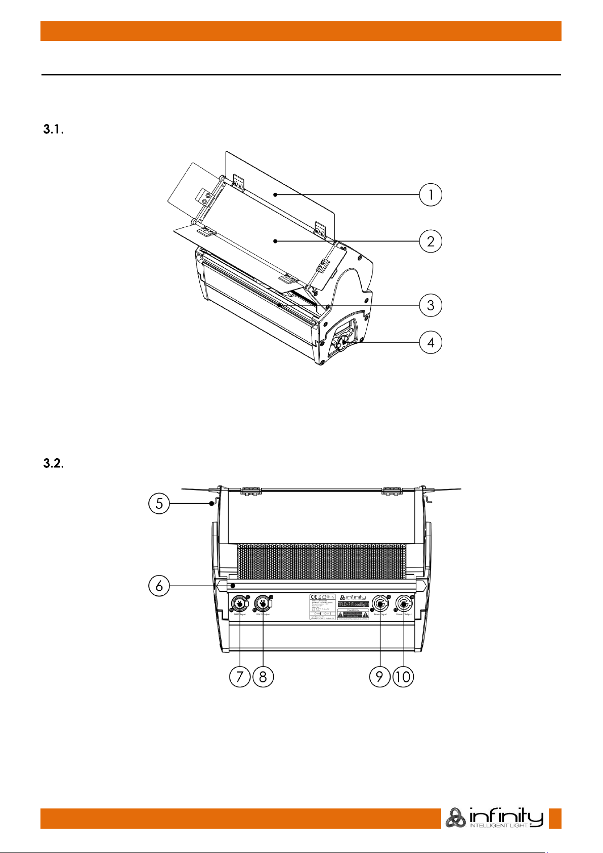
Front View ............................................................................................................................................................9
Back View ............................................................................................................................................................9
Product Specifications ....................................................................................................................................10
Dimensions.........................................................................................................................................................11
4. Installation ..........................................................................................................................................................12
Safety Instructions for Installation ..................................................................................................................12
Personal Protective Equipment .....................................................................................................................12
Installation Site Requirements ........................................................................................................................12
Rigging ...............................................................................................................................................................12
Beam Shaper Installation ................................................................................................................................14
Connecting to Power Supply.........................................................................................................................15
Power Linking of Multiple Devices.................................................................................................................15
5. Setup ...................................................................................................................................................................16
Warnings and Precautions .............................................................................................................................16
Stand-alone Setup ...........................................................................................................................................16
DMX Connection..............................................................................................................................................16
DMX-512 Protocol .......................................................................................................................................16
DMX Cables .................................................................................................................................................17
DMX Linking..................................................................................................................................................17
DMX Addressing..........................................................................................................................................18
6. Operation ...........................................................................................................................................................19
Safety Instructions for Operation...................................................................................................................19
Control Modes ..................................................................................................................................................19
Focus Mode .................................................................................................................................................19
Control Panel ....................................................................................................................................................20
Start-up...............................................................................................................................................................20
Menu Overview ................................................................................................................................................21
Main Menu Options .........................................................................................................................................23
DMX Channel Mode ..................................................................................................................................23
DMX Address ...............................................................................................................................................23
Manual Mode .............................................................................................................................................24
Color .....................................................................................................................................................24
Dimmer Curve .............................................................................................................................................25
Dimmer Speed ............................................................................................................................................25
CCT Mode....................................................................................................................................................25
Tungsten .......................................................................................................................................................26
DMX Lost .......................................................................................................................................................26
Fan Mode.....................................................................................................................................................27
PWM Frequency .....................................................................................................................................27
Calibration ...............................................................................................................................................27
Display ......................................................................................................................................................27
Info.............................................................................................................................................................28
Factory......................................................................................................................................................28

3
TFLD-7 Floodlight
Product code: 200400
DMX Channels ..................................................................................................................................................29
DMX Channels Overview ..........................................................................................................................29
Dimmer (1 Channel), Basic (5 Channels), Tungsten (6 Channels) ....................................................30
RGB Pro (10 Channels), CMY Pro (10 Channels), HSI Pro (10 Channels)..........................................33
RAW (20 Channels) ....................................................................................................................................36
7. Troubleshooting .................................................................................................................................................39
8. Maintenance .....................................................................................................................................................40
Safety Instructions for Maintenance.............................................................................................................40
Preventive Maintenance................................................................................................................................40
Basic Cleaning Instructions .......................................................................................................................41
Corrective Maintenance................................................................................................................................41
9. Deinstallation, Transportation and Storage ....................................................................................................42
Instructions for Deinstallation..........................................................................................................................42
Instructions for Transportation ........................................................................................................................42
Storage...............................................................................................................................................................42
10. Disposal ..............................................................................................................................................................42
11. Approval.............................................................................................................................................................42

4
TFLD-7 Floodlight
Product code: 200400
1. Introduction
Before Using the Product
Important
Read and follow the instructions in this user manual before installing, operating or
servicing this product.
The manufacturer will not accept liability for any resulting damages caused by the non-observance of
this manual.
After unpacking, check the contents of the box. If any parts are missing or damaged, contact your
Highlite International dealer.
Your shipment includes:
●Infinity TFLD-7 Floodlight
●Schuko to Neutrik powerCON cable (1,4 m)
●Beam shaper
●1 x Mounting bracket set
●1 x Mounting bracket
●2 x Mounting screws
●2 x Hex nuts
●Safety bracket set:
●1 x Safety bracket
●1 x Mounting screw
●1 x Hex nut
●User manual
Fig. 01
Intended Use
This device is intended for professional use as a floodlight. It is suitable only for indoor installation. This
device is not suitable for households and for general lighting.
Any other use, not mentioned under intended use, is regarded as non-intended and incorrect use.
Product Lifespan
This device is not designed for permanent operation. Disconnect the device from the electrical power
supply when the device is not in operation. This will reduce the wear and will improve the device’s
lifespan.
LEDs Lifespan
The light output of the LEDs gradually decreases over time (lumen depreciation). High operating
temperatures contribute to this process. You can extend the lifespan of the LEDs by providing adequate
ventilation and operating the LEDs at the lowest possible brightness.
Text Conventions
Throughout the user manual the following text conventions are used:
●Buttons: All buttons are in bold lettering, for example “Press the UP/DOWN buttons”
●References: References to chapters and parts of the device are in bold lettering, for example:
“Refer to 2. Safety”, “press the beam shaper lock (05)”
●0–255: Defines a range of values
●Notes: Note: (in bold lettering) is followed by useful information or tips

5
TFLD-7 Floodlight
Product code: 200400
Symbols and Signal Words
Safety notes and warnings are indicated throughout the user manual by safety signs.
Always follow the instructions provided in this user manual.
DANGER
Indicates an imminently hazardous situation which, if not avoided, will result in
death or serious injury.
WARNING
Indicates a potentially hazardous situation which, if not avoided, could result in
death or serious injury.
CAUTION
Indicates a potentially hazardous situation, which, if not avoided, may result in
minor or moderate injury.
Attention
Indicates important information for the correct operation and use of the
product.
Important
Read and observe the instructions in this document.
Electrical hazard
Hot surface
Eye damage hazard
Provides important information about the disposal of this product.
Symbols on the Information Label
This product is provided with an information label. The information label is located at the backside of the
device.
The information label contains the following symbols:
This device is designed for indoor use.
This device shall not be treated as household waste.
Replace any cracked protective shield.
Minimum distance from lighted objects.
Minimum distance from other objects.
Caution: Risk of electric shock. Disconnect input power before opening.
Warning: This appliance must be earthed.

6
TFLD-7 Floodlight
Product code: 200400
2. Safety
Important
Read and follow the instructions in this user manual before installing, operating or
servicing this product.
The manufacturer will not accept liability for any resulting damages caused by the non-observance of
this manual.
Warnings and Safety Instructions
DANGER
Danger for children
For adult use only. The device must be installed beyond the reach of children.
●Do not leave various parts of the packaging (plastic bags, polystyrene foam, nails, etc.) within
children’s reach. Packaging material is a potential source of danger for children.
DANGER
Electric shock caused by dangerous voltage inside
There are areas within the device where dangerous touch voltage (> 120 V DC) may be present.
●Do not open the device or remove any covers.
●Do not operate the device if the covers or the housing are open. Before operation, check if the
housing is firmly closed and all screws are tightly fastened.
●Disconnect the device from electrical power supply before service and maintenance, and when the
device is not in use.
DANGER
Electric shock caused by short-circuit
This device falls under IEC protection class I.
●Make sure that the device is electrically connected to ground (earth). Connect the device only to a
socket-outlet with ground (earth) connection.
●Do not cover the ground (earth) connection.
●Do not bypass the thermostatic switch or fuses.
●Do not let the power cable come into contact with other cables. Handle the power cable and all
connections with the mains with caution.
●Do not modify, bend, mechanically strain, put pressure on, pull or heat up the power cable.
●Make sure that the power cable is not crimped or damaged. Examine the power cable periodically
for any defects.
●Do not immerse the device in water or other liquids. Do not install the device in a location where
flooding may occur.
●Do not use the device during thunderstorms. Disconnect the device from the electrical power supply
immediately.

7
TFLD-7 Floodlight
Product code: 200400
WARNING
Risk of burns due to hot surface
The surface and the inner parts of the device can become very hot during operation.
●Do not touch the device during operation.
●Allow the device to cool down for at least 15 minutes before handling.
WARNING
Risk of epileptic shock
Strobe lighting can trigger seizures in photosensitive epilepsy. Sensitive persons should avoid looking at
strobe lights.
WARNING
Possible eye damage caused by high light intensity
Possibly hazardous optical radiation emitted from this device.
●Do not look at the operating light source. May be harmful to the eye.
●Do not look at the light source with optical instruments that may concentrate the light output.
●Make sure that persons are not looking directly into the light source when the device lights up
suddenly. This can happen when the device is powered or when it receives DMX signal, or when
certain menu items are selected.
●Disconnect power supply before servicing.
●Wear protective goggles if looking into light source during service or maintenance.
Attention
Power supply
●Before connecting the device to the power supply, make sure that the current, voltage and
frequency match the input voltage, current and frequency specified on the information label on the
device.
●Make sure that the cross-sectional area of the extension cords and power cables is sufficient for the
required power consumption of the device.
Attention
General safety
●Do not insert objects into the air vents.
●Do not connect the device to a dimmer pack.
●Do not switch the device on and off in short intervals. This decreases the device’s life.
●Do not shake the device. Avoid brute force when installing or operating the device.
●Change the lens or the LEDs if they are visibly damaged to such an extent that their effectiveness is
impaired, for example by cracks or deep scratches. Contact your Highlight International dealer for
more information, as servicing can be performed only by instructed or skilled persons.
●If the device is dropped or struck, disconnect the device from the electrical power supply
immediately.

8
TFLD-7 Floodlight
Product code: 200400
●If the device is exposed to extreme temperature variations (e.g. after transportation), do not switch it
on immediately. Let the device reach room temperature before switching it on, otherwise it may be
damaged by the formed condensation.
●If the device fails to work properly, discontinue the use immediately.
Attention
For professional use only
This device shall be used only for the purposes it is designed for.
This device is designed to be used as a professional stage light effect. Any incorrect use may lead to
hazardous situations and result in injuries and material damage.
●This device is not suitable for households and for general lighting.
●This device is not designed for permanent operation.
●This device does not contain user-serviceable parts. Unauthorized modifications to the device will
render the warranty void. Such modifications may result in injuries and material damage.
Attention
Before each use, examine the device visually for any defects.
Make sure that:
●All screws used for installing the device or parts of the device are tightly fastened and are not
corroded.
●The safety devices are not damaged.
●There are no deformations on housings, fixations and installation points.
●The lens is not cracked or damaged.
●The power cables are not damaged and do not show any material fatigue.
Attention
Do not expose the device to conditions that exceed the rated IP class conditions.
This device is IP20 rated. IP (Ingress Protection) 20 class provides protection against solid objects greater
than 12 mm, such as fingers, and no protection against harmful ingress of water.
Requirements for the User
This product may be used by ordinary persons. Maintenance may be carried by ordinary persons.
Installation and service shall be carried out only by instructed or skilled persons. Contact your Highlite
International dealer for more information.
Instructed persons have been instructed and trained by a skilled person, or are supervised by a skilled
person, for specific tasks and work activities associated with the installation, service and maintenance of
this product, so that they can identify risks and take precautions to avoid them.
Skilled persons have training or experience, which enables them to recognize risks and to avoid hazards
associated with the installation, service and maintenance of this product.
Ordinary persons are all persons other than instructed persons and skilled persons. Ordinary persons
include not only users of the product but also any other persons that may have access to the device or
who may be in the vicinity of the device.

9
TFLD-7 Floodlight
Product code: 200400
3. Description of the Device
The Infinity TFLD-7 is a compact floodlight suitable for indoor venues. It features a custom-designed
7-color LED array which produces 64 theatrical colors for the perfect floodlight effect.
Front View
Fig. 02
01) Integrated barndoor
02) Beam shaper
03) Mounting groove
04) Control panel: LCD display and control buttons
Back View
Fig. 03
05) 2 x Beam shaper locks
06) Mounting groove
07) 5-pin DMX signal connector IN
08) 5-pin DMX signal connector OUT
09) Neutrik powerCON connector IN (Blue)
10) Neutrik powerCON connector OUT (Gray)

10
TFLD-7 Floodlight
Product code: 200400
Product Specifications
Model:
TFLD-7 Floodlight
Electrical:
Input voltage:
100–240 V AC, 50/60 Hz
Power consumption:
160 W (max)
Fuse:
T1,2 A, 250 V AC
Power factor:
0,96
Physical:
Dimensions:
318 x 136 x 239 mm (L x W x H)
Weight:
5,34 kg (with the integrated barndoor and the beam shaper)
Movement:
Tilt adjustment:
170° (manual)
Optics:
Light source:
150 W Lumileds 7-color LED engine
Dimmer:
0–100 %
Strobe:
0–20 Hz
Beam angle:
40° (supplied accessory), 60° (supplied accessory), 90° (optional
accessory)
Light quality:
> 96 CRI (High CRI Mode)
Luminous flux:
3000 lm
Color temperature:
2000–8000 K
Operation and control:
Control:
DMX-512, RDM, manual
DMX channels:
Dimmer (1 channel), Basic (5 channels), Tungsten (6 channels), HSI Pro
(10 channels), RGB Pro (10 channels), CMY Pro (10 channels), RAW (20
channels)
Control panel:
LCD display, control buttons and control wheel
Connections:
Power connections:
Neutrik powerCON connectors IN/OUT
Data connections:
5-pin DMX connectors IN/OUT
Signal pinouts:
Pin 1 (ground), pin 2 (-), pin 3 (+), pin 4 (N/C), pin 5 (N/C)
Construction:
Housing:
Machined aluminum, sheet metal, molded engineering grade plastics
Color:
Black
IP rating:
IP20
Cooling:
Internal fan (Silent, Auto, and Full modes)
Thermal:
Maximum ambient temperature ta:
40 °C
Maximum housing temperature tc:
70 °C
Minimum distance:
Minimum distance from flammable surfaces:
0,8 m
Minimum distance to lighted object:
0,8 m

11
TFLD-7 Floodlight
Product code: 200400
Dimensions
Fig. 04
Fig. 05
Fig. 06

12
TFLD-7 Floodlight
Product code: 200400
4. Installation
Safety Instructions for Installation
WARNING
Incorrect installation can cause serious injuries and damage of property.
If trussing systems are used, installation must be carried out only by instructed or skilled persons.
Follow all applicable European, national and local safety regulations concerning rigging and trussing.
Personal Protective Equipment
During installation and rigging wear personal protective equipment in compliance with the national and
site-specific regulations.
Installation Site Requirements
●The device can be used only indoors.
●The device can be mounted to a truss or another rigging structure in any orientation.
●The device can be placed on flat surface.
●The minimum distance to other objects must be bigger than 0,8 m.
●The maximum ambient temperature ta= 40 °C must never be exceeded.
●The relative humidity must not exceed 50 % with an ambient temperature of 40 °C.
Rigging
The device can be positioned on a flat surface or mounted to a truss or other rigging structure in any
orientation. Make sure that all loads are within the pre-determined limits of the supporting structure.
The device has 3 mounting grooves, located at the front, at the back and on the bottom, as shown in
Fig. 07. The device is delivered with a mounting bracket set and a safety bracket set, see Fig. 08.
Mounting bracket set:
●1 x Mounting bracket
●2 x Mounting screws
●2 x Hex nuts
Safety bracket set:
●1 x Safety bracket
●1 x Hex nut
●1 x Mounting screw
Fig. 07
Fig. 08
CAUTION
Restrict the access under the work area during rigging and/or derigging.

13
TFLD-7 Floodlight
Product code: 200400
To mount the device, follow the steps below:
01) Slide the 3 mounting screws in the mounting groove (03), as shown in Fig. 09.
02) Place the mounting bracket and the safety bracket on the mounting screws, so that the mounting
screws fit into the respective openings, as shown in Fig. 09.
03) Adjust the position of the mounting bracket.
04) Fasten the mounting bracket and the safety bracket in position with the 3 hex nuts.
05) Install the clamp, as shown in Fig. 10. Make sure that you use a clamp suitable for attaching the
device to a truss.
Fig. 09
Fig. 10
06) Attach the device to the supporting structure. Make sure that the device cannot move freely.
07) Secure the device with a secondary suspension, for example a safety cable. Make sure that the
secondary suspension can hold 10 times the weight of the device. If possible, the secondary
suspension should be attached to a supporting structure independent of the primary suspension. Put
the safety cable through the opening on the safety bracket, as shown in Fig. 10.
After mounting is completed, you can adjust the angle of the device (see Fig. 11) and the position of the
barndoor. The tilting angle of the device is 170°. To quickly start the device, you can turn on focus mode.
See 6.2.1. Focus Mode on page 19 for more information.
Fig. 11

14
TFLD-7 Floodlight
Product code: 200400
Beam Shaper Installation
The TFLD-7 Floodlight is delivered with 2 beam shapers (40° and 60°). You can order an additional 90°
beam shaper. Contact your Highlite International dealer for more information.
To install the beam shaper follow the steps bellow:
01) Press one of the beam shaper locks (05) and at the same time slide the beam shaper out of the
device, as shown in Fig. 12.
02) Take the other beam shaper.
03) Press the beam shaper lock (05) and at the same time slide the beam shaper in its place, as shown in
Fig. 13.
04) Release the beam shaper lock (05) to lock the beam shaper in its place.
Fig. 12
Fig. 13

15
TFLD-7 Floodlight
Product code: 200400
Connecting to Power Supply
DANGER
Electric shock caused by short-circuit
The device accepts AC mains power at 100–240 V and 50/60 Hz. Do not supply power at any other
voltage or frequency to the device.
This device falls under IEC protection class I. Make sure that the device is always electrically connected
to the ground (earth).
Before connecting the device to the socket-outlet:
●Make sure that the power supply matches the input voltage specified on the information label on
the device.
●Make sure that the socket-outlet has ground (earth) connection.
Connect the device to the socket-outlet with the power plug. Do not connect the device to a dimmer
circuit, as this may damage the device.
Power Linking of Multiple Devices
This device supports power linking. Power can be relayed to another device via the power OUT
connector. Note that the input and the output connectors have different designs: one type cannot be
connected to the other.
Power linking of multiple devices must be carried out only by instructed or skilled persons.
WARNING
Incorrect power linking may lead to overload of the electrical circuit and result in serious
injuries and damage of property.
To prevent overload of the electrical circuit, when power linking multiple devices:
●Use cables with sufficient current-carrying capacity. The power cable supplied with the device is not
suitable for power linking of multiple devices.
●Make sure that the total current draw of the device and all connected devices does not exceed the
rated capacity of the power cables and the circuit breaker.
●Do not link more devices on one power link than the maximum recommended number.
Maximum recommended number of devices:
●at 100–120 V: 8 devices TFLD-7 Floodlight
●at 200–240 V: 15 devices TFLD-7 Floodlight

16
TFLD-7 Floodlight
Product code: 200400
5. Setup
Warnings and Precautions
Attention
Connect all data cables before supplying power.
Disconnect power supply before connecting or disconnecting data cables.
Stand-alone Setup
When the TFLD-7 Floodlight is not connected to a DMX controller, it functions as a stand-alone device in
manual control mode.
For more information about the control modes, refer to 6.2. Control Modes on page 19.
DMX Connection
DMX-512 Protocol
You need a DMX serial data link to run light shows of one or more devices using a DMX-512 controller.
The TFLD-7 Floodlight has 5-pin DMX signal IN and OUT connectors.
The pin assignment is as follows: pin 1 (ground), pin 2 (-), pin 3 (+), pin 4 (N/C), pin 5 (N/C).
Devices on a serial data link must be daisy-chained in a single line. The number of devices that you can
control on one data link is limited by the combined number of the DMX channels of the connected
devices and the 512 channels available in one DMX universe.
To comply with the TIA-485 standard, no more than 32 devices should be connected on one data link.
In order to connect more than 32 devices on one data link, you must use a DMX optically isolated
splitter/booster, otherwise this may result in deterioration of the DMX signal.
Note:
●Maximum recommended DMX data link distance: 300 m
●Maximum recommended number of devices on a DMX data link: 32 devices

17
TFLD-7 Floodlight
Product code: 200400
DMX Cables
Shielded twisted-pair cables with 5-pin XLR connectors must be used for reliable DMX connection. You
can purchase DMX cables directly from your Highlite International dealer or make your own cables.
If you use XLR audio cables for DMX data transmission, this may lead to signal degradation and unreliable
operation of the DMX network.
When you make your own DMX cables, make sure that you connect the pins and wires correctly as
shown in Fig. 14.
Fig. 14
DMX Linking
To connect multiple devices on one DMX data link, follow the steps below:
Use a 5-pin DMX cable to connect the DMX OUT connector of the lighting controller to the DMX IN
connector of the first device.
02) Connect the first device’s DMX OUT connector to the second device’s DMX IN connector with a
5-pin DMX cable.
03) Repeat step 2 to connect all devices in a daisy-chain as shown in Fig. 15.
04) Connect a DMX terminator (120 Ω resistor) to the DMX OUT connector of the last device on the data
link.
Fig. 15

18
TFLD-7 Floodlight
Product code: 200400
DMX Addressing
In a setup with multiple devices, make sure that you set the DMX starting address of each device
correctly. The TFLD-7 Floodlight has 7 DMX channel modes: Dimmer (1 channel), Basic (5 channels),
Tungsten (6 channels), HSI Pro (10 channels), RGB Pro (10 channels), CMY Pro (10 channels), and RAW (20
channels).
If you want to connect multiple devices on one data link and use them in 20-channel mode, for
example, follow the steps below:
Set the starting address of the 1st device on the data link to 1 (001).
02) Set the starting address of the 2nd device on the data link to 21 (021), as 1 + 20 = 21.
03) Set the starting address of the 3rd device on the data link to 41 (041), as 21 + 20 = 41.
04) Continue assigning the starting addresses of the remaining devices by adding each time 20 to the
previous number.
Make sure that you do not have any overlapping channels in order to control each TFLD-7 Floodlight
correctly. If two or more devices are addressed similarly, they will work similarly.

19
TFLD-7 Floodlight
Product code: 200400
6. Operation
Safety Instructions for Operation
Attention
This device must be used only for the purposes it is designed for.
This device is intended for professional use as a floodlight. It is suitable only for indoor installation. This
device is not suitable for households and for general lighting.
Any other use, not mentioned under intended use, is regarded as non-intended and incorrect use.
Attention
Power supply
Before connecting the device to the power supply, make sure that the current, voltage and frequency
match the input voltage, current and frequency specified on the information label on the device.
Control Modes
The TFLD-7 Floodlight can be operated with a DMX controller and as a stand-alone device.
The TFLD-7 Floodlight supports the following control modes:
●Stand-alone: Manual operation
●DMX-512: Dimmer (1 channel), Basic (5 channels), Tungsten (6 channels), HSI Pro (10
channels), RGB Pro (10 channels), CMY Pro (10 channels), RAW (20
channels)
For more information about how to connect the devices, refer to 5. Setup on pages 16–18.
To operate the device manually as a stand-alone device:
01) Select Manual Mode in the main menu. See 6.6.3. Manual Mode on page 24 for more information.
02) Adjust the dimmer and color temperature settings, or select a color preset.
To operate the device with a DMX controller:
01) Set the DMX starting address of the device in the DMX Address submenu. See 5.3.4. DMX Addressing
on page 18 and 6.6.2. DMX Address on page 23.
02) Select the DMX channel mode. See 6.6.1. DMX Channel Mode on page 23 for more information. See
6.7. DMX Channels on pages 29–38 for complete overview of all DMX channels.
Focus Mode
With focus mode you can quickly and easily start the device. This can be helpful if you want to adjust the
beam angle and the position of the barndoor during installation of the device. In focus mode the LEDs
remain on for 3 min with light output at 3200 K.
01) Press and hold down the BACK/HOME button for 3 s. The focus mode will be activated.
02) Press the BACK/HOME button again to exit the focus mode. If no button is pressed, the device will
automatically exit focus mode after 3 min.
This manual suits for next models
1
Table of contents
Other Infinity Floodlight manuals