Infinium WELD STAR WS-PC40-DV User manual


2
Introducon to your new product
Thank you for selecng this Weld Star Innium product.
This product manual has been designed to ensure that you get the most from your new Weld Star
product. Please ensure that you are fully conversant with the informaon provided paying parcular
aenon to the safety precauons. The informaon will help protect yourself and others against the
potenal hazards that you may come across.
Please ensure that you carry out daily and periodic maintenance checks to ensure years of reliable and
trouble free operaon.
Please call your Weld Star distributor in the unlikely event of a problem occurring.
Please record below the details of your new Weld Star product as these may be required for warranty
purposes should you require assistance or spare parts.
Date purchased ________________________________________
Purchased from ________________________________________
Model name ________________________________________
Serial number ________________________________________
(The serial number is normally located on the product packaging, top or underside of the machine)
Disclaimer
Whilst every eort has been made to ensure that the informaon contained within this
manual is complete and accurate, no liability can be accepted for any errors or omissions.
Please note:
Products are subject to connual development and may be subject to change without
noce. www.weldstar.uk
No part of this manual may be copied or reproduced by any means without the wrien
permission of Wilkinson Star Limited.

3
CONTENTS
Page
Your New Product 2
Index 3
Safety Instrucons 4
General electrical and operang safety 5
PPE and Welding processes lens shade selector guide 6
Fume and welding gases and re risks 7
The working environment, Magnec elds and cylinder safety 8
Noise and re awareness, hot parts and RF/LF declaraons 9
Materials and their disposal 9
Package Contents and Unpacking 9
Product Overview 10
Product details and applicaon 11
Technical Specicaons 12
Descripon of Controls PC-40 13
Descripon of Controls PC-65 15
Descripon of Controls PC-120 17
What is Plasma? 19
Installaon 20
Operaon - User Setup 21
Operaon - Modes of Cung 25
Operaon - Cung Techniques 28
Plasma Hand Torch TH-35 Consumable breakdown PC-40 31
Plasma Hand Torch UPH-125 Consumable breakdown PC-65 32
Plasma Hand Torch UPH-125 Consumable breakdown PC-120 33
Plasma Cung Problems 35
Troubleshoong 36
Maintenance 37
Plasma Torch Plug and Socket Wiring Diagram 37
WEEE Disposal 38
RoHS Compliance Declaraon 38
UKCA Declaraon of Conformity 38
EC Declaraon of Conformity 39
Statement of Warranty 40
Notes 41
Weld Star Contact Details 42

4
SAFETY INSTRUCTIONS
These general safety norms cover both arc welding machines and plasma cung
machines unless otherwise noted. The user is responsible for installing and operang
the equipment in accordance with the enclosed instrucons.
It is important that users of this equipment protect themselves and others from harm, or even death.
The equipment must only be used for the purpose it was designed for. Using it in any other way could
result in damage or injury and in breach of the safety rules.
Only suitably trained and competent persons should operate the equipment.
Pacemaker wearers should consult their doctor prior to using this equipment.
PPE and workplace safety equipment must be compable for the applicaon of the work involved.
Always carry out a risk assessment before carrying out any welding or cung acvity.
General electrical safety
The equipment should be installed by a qualied person and in accordance with current
standards in operaon.
It is the users responsibility to ensure that the equipment is connected to a suitable power
supply. Consult your ulity supplier if required.
Do not use the equipment with the covers removed. Do not touch live electrical parts or parts
which are electrically charged. Turn o all equipment when not in use.
In the case of abnormal behaviour of the equipment, the equipment should be checked by a suitably
qualied service engineer.
If earth bonding of the work piece is required, bond it directly with a separate cable with a current
carrying capacity capable of carrying the maximum capacity of the machine current.
Cables (both primary supply and welding) should be regularly checked for damage and overheang.
Never use worn, damaged, under sized or poorly jointed cables.
Insulate yourself from work and earth using dry insulang mats or covers big enough to prevent any
physical contact.
Never touch the electrode if you are in contact with the work piece return.
Do not wrap cables over your body.
Ensure that you take addional safety precauons when you are welding in electrically hazardous
condions such as damp environments, wearing wet clothing and metal structures.
Try to avoid welding in cramped or restricted posions.
Ensure that the equipment is well maintained. Repair or replace damaged or defecve parts immediately.
Carry out any regular maintenance in accordance with the manufacturers instrucons.
The EMC classicaon of this product is class A in accordance with electromagnec compability
standards CISPR 11 and IEC 60974-10 and therefore the product is designed to be used in industrial
environments only.
WARNING: This class A equipment is not intended for use in residenal locaons where the electrical
power is provided by a public low-voltage supply system. In those locaons it may be dicult to ensure
the electromagnec compability due to conducted and radiated disturbances.
General operang safety
Never carry the equipment or suspend it by the carrying strap or handles during welding.
Never pull or li the machine by the welding torch or other cables.
Always use the correct li points or handles. Always use the transport under gear as
recommended by the manufacturer.
Never li a machine with the gas cylinder mounted on it.
If the operang environment is classied as dangerous, only use S-marked welding equipment with a safe
idle voltage level. Such environments may be for example: humid, hot or restricted accessibility spaces.

5
SAFETY INSTRUCTIONS
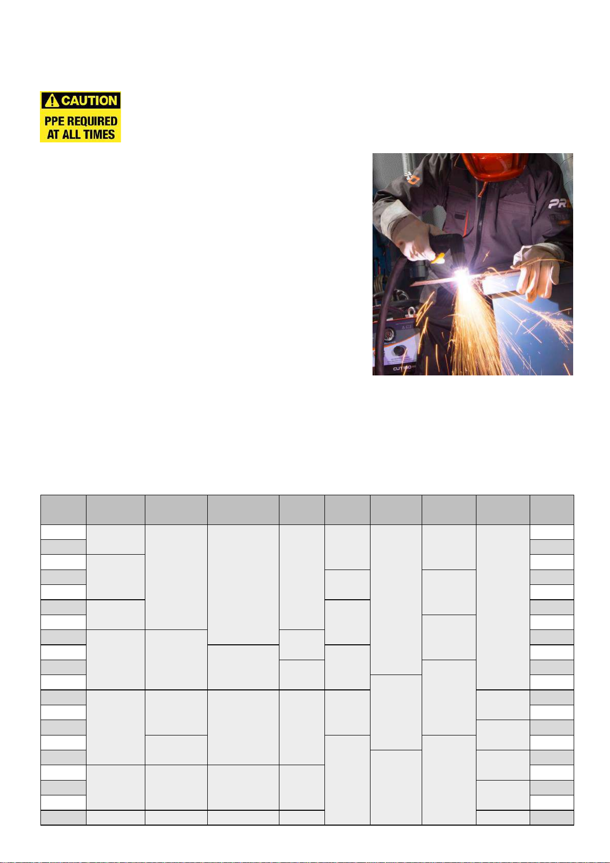
Use of Personal Protecve Equipment (PPE)
Welding arc rays from all welding and cung processes can produce intense, visible
and invisible (ultraviolet and infrared) rays that can burn eyes and skin.
• Wear an approved welding helmet ed with an appropriate
shade of lter lens to protect your face and eyes when
welding, cung or watching.
• Wear approved safety glasses with side shields under your
helmet.
• Never use any equipment that is damaged, broken or faulty.
• Always ensure there are adequate protecve screens or
barriers to protect others from ash, glare and sparks from
the welding and cung area.
• Ensure that there are adequate warnings that welding or
cung is taking place.
• Wear suitable protecve ame resistant clothing, gloves and
footwear.
• Ensure adequate extracon and venlaon is in place prior to
welding and cung to protect users and all workers nearby.
• Check and be sure the area is safe and clear of ammable material before carrying out any welding
or cung.
Some welding and cung operaons may produce noise. Wear safety ear protecon to protect your
hearing if the ambient noise level exceeds the local allowable limit (e.g: 85 dB).
Welding and Cung Lens Shade Selector Guide
Current MMA
Electrodes
MIG
Light Alloys
MIG
Heavy Metals MAG TIG Plasma
Cung
Plasma
Welding
Air Arc
Gouging Current
10 8
10 10 10
9
11
10
10
10
15 15
20
9
20
30 10 11
30
40 40
60 10 11
60
80
12
80
100
11 11
11 100
125
11 12
125
150 12
13
150
175
12
175
200
12
12
12 13
13 11 200
225 225
250 12 250
275 13
14 14
275
300
13
13 300
350
13 14 13 14
350
400 14 400
450 450
500 14 15 14 15 15 500

6
SAFETY INSTRUCTIONS
Safety against fumes and welding gases
The HSE have idened welders as being an ‘at risk’ group for occupaonal diseases arising
from exposure to dusts, gases, vapours and welding fumes. The main idened health eects
are pneumonia, asthma, chronic obstrucve pulmonary disease (COPD), lung and kidney
cancer, metal fume fever (MFF) and lung funcon changes.
During welding and hot cung ‘hot work’ operaons, fumes are produced which are
collecvely known as welding fume. Depending upon the type of welding process being performed, the
resultant fume generated is a complex and highly variable mixture of gases and parculates.
Regardless of the length of welding being carried out, all welding fume, including mild steel welding
requires suitable engineering controls to be in place which is
usually Local Exhaust Venlaon (LEV) extracon to reduce the
exposure to welding fume indoors and where LEV does not
adequately control exposure it should also be enhanced by
using suitable respiratory protecve equipment (RPE) to assist
with protecng against residual fume.
When welding outdoors appropriate RPE should be used.
Prior to undertaking any welding tasks an appropriate risk
assessment should be carried out to ensure expected control
measures are in place.
Locate the equipment in a well-venlated posion and keep your head out of the welding fume.
Do not breathe in the welding fume.
Ensure the welding zone is well-venlated and provision should be made for suitable local fume
extracon system to be in place.
If venlaon is poor, wear an approved airfed welding helmet or respirator.
Read and understand the Material Safety Data Sheets (MSDS’s) and the manufacturer’s instrucons for
metals, consumable, coangs, cleaners and de-greasers.
Do not weld in locaons near any de-greasing, cleaning or spraying operaons.
Be aware that heat and rays of the arc can react with vapours to form highly toxic and irritang gases.
For further informaon please refer to the HSE website www.hse.gov.uk for related documentaon.
Precauons against re and explosion
Avoid causing res due to sparks and hot waste or molten metal.
Ensure that appropriate re safety devices are available near the welding and cung area.
Remove all ammable and combusble materials from the welding, cung and surrounding
areas.
Do not weld or cut fuel and lubricant containers, even if empty. These must be carefully
cleaned before they can be welded or cut.
Always allow the welded or cut material to cool before touching it or
placing it in contact with combusble or ammable material.
Do not work in atmospheres with high concentraons of combusble
fumes, ammable gases and dust.
Always check the work area half an hour aer cung to make sure that
no res have begun.
Take care to avoid accidental contact of the torch electrode to metal
objects, as this could cause arcs, explosion, overheang or re.
Know and understand your re exnguishers
An example of personal fume protecon

7
SAFETY INSTRUCTIONS
The working environment
Ensure the machine is mounted in a safe and stable posion allowing for cooling air circulaon.
Do not operate equipment in an environment outside the laid down operang parameters.
The welding power source is not suitable for use in rain or snow.
Always store the machine in a clean, dry space.
Ensure the equipment is kept clean from dust build up.
Always use the machine in an upright posion.
Protecon from moving parts
When the machine is in operaon keep away from moving parts such as motors and fans.
Moving parts, such as the fan, may cut ngers and hands and snag garments.
Protecons and coverings may be removed for maintenance and managed only by qualied
personnel aer rst disconnecng the power supply cable.
Replace the coverings and protecons and close all doors when the intervenon is nished and before
starng the equipment.
Take care to avoid geng ngers trapped when loading and feeding wire during set up and operaon.
When feeding wire be careful to avoid poinng it at other people or towards your body.
Always ensure machine covers and protecve devices are in operaon.
Risks due to magnec elds
The magnec elds created by high currents may aect the operaon of pacemakers or
electronically controlled medical equipment.
Wearers of vital electronic equipment should consult their physician before beginning any arc
welding, cung, gouging or spot welding operaons.
Do not go near welding equipment with any sensive electronic equipment as the magnec
elds may cause damage.
Keep the torch cable and work return cable as close to each other as possible throughout their length.
This can help minimise your exposure to harmful magnec elds.
Do not wrap the cables around the body.
Handling of compressed gas cylinders and regulators
Mishandling gas cylinders can lead to rupture and the release of high pressure gas.
Always check the gas cylinder is the correct type for the welding to be carried out.
Always store and use cylinders in an upright and secure posion.
All cylinders and pressure regulators used in welding operaons should be handled with care.
Never allow the electrode, electrode holder or any other electrically “hot” parts to touch a
cylinder.
Keep your head and face away from the cylinder valve outlet when opening the cylinder valve.
Always secure the cylinder safely and never move with regulator and hoses connected.
Use a suitable trolley for moving cylinders.
Regularly check all connecons and joints for leaks.
Full and empty cylinders should be stored separately.
Never deface or alter any cylinder

8
SAFETY INSTRUCTIONS
Fire awareness
The cung and welding process can cause serious risks of re or explosion.
Cung or welding sealed containers, tanks, drums or pipes can cause explosions.
Sparks from the welding or cung process can cause res and burns.
Check and risk assess the area is safe before doing any cung or welding.
Venlate all ammable or explosive vapour from the workplace.
Remove any and all ammable materials away from the working area. If necessary, cover ammable
materials or containers with approved covers (following manufacturers instrucons) if unable to
remove from the immediate area.
Do not cut or weld where the atmosphere may contain ammable dust, gas or liquid vapour.
Always have the appropriate re exnguisher nearby and know how to use it.
Hot parts
Always be aware that material being cut or welded will get very hot and hold that heat for a
considerably long me which will cause severe burns if the appropriate PPE is not worn.
Do not touch hot material or parts with bare hands.
Always allow for a cooling down period before working on material recently cut or welded.
Use the appropriate insulated welding gloves and clothing to handle hot parts to prevent burns.
Noise awareness
The cung and welding process can generate noise that can cause permanent damage to your
hearing. Noise from cung and welding equipment can damage hearing.
Always protect your ears from noise and wear approved and appropriate ear protecon if
noise levels are high.
Consult with your local specialist if you are unsure how to test for noise levels.
RF Declaraon
Equipment that complies with direcve 2014/30/EU concerning electromagnec compability
(EMC) and the technical requirements of EN60974-10 is designed for use in industrial buildings
and not for domesc use where electricity is provided via the low voltage public distribuon
system.
Dicules may arise in assuring class A electromagnec compability for systems installed in domesc
locaons due to conducted and radiated emissions.
In the case of electromagnec problems, it is the responsibility of the user to resolve the situaon.
It may be necessary to shield the equipment and t suitable lters on the mains supply.
LF Declaraon
Consult the data plate on the equipment for the power supply requirements.
Due to the elevated absorbance of the primary current from the power supply network, high
power systems aect the quality of power provided by the network. Consequently, connecon
restricons or maximum impedance requirements permied by the network at the public network
connecon point must be applied to these systems.
In this case, the installer or the user is responsible for ensuring the equipment can be connected,
consulng the electricity provider if necessary.

9
SAFETY INSTRUCTIONS
Materials and their disposal
Welding equipment is manufactured with BSI published standards meeng CE requirements for
materials which do not contain any toxic or poisonous materials dangerous to the operator.
Do not dispose of the equipment with normal waste. The European Direcve 2012/19/EU on
Waste Electrical and Electronic Equipment states that electrical equipment that has reached its end of
life must be collected separately and returned to an environmentally compable recycling facility for
disposal.
For more detailed informaon please refer to the HSE website www.hse.gov.uk
PACKAGE CONTENTS AND UNPACKING
Supplied within your new Weld Star Innium product package will be the following items with each
model. Use care when unpacking the contents and ensure all items are present and not damaged.
If damage is noted or items are missing, please contact the supplier in the rst instance and before
installing or using the product.
Record the product model, serial numbers and purchase date in the informaon secon found on the
inside front page of this operang manual.
Weld Star WS-PC40-DV
PC-40-DV Plasma Power Source
4m TH-35 Plasma Hand Torch
Air Regulator
Work Return Lead
PCL Air Fing
Operang Manual
Weld Star WS-PC65
PC-65 Plasma Power Source
6m UPH-125 Plasma Hand Torch
Consumable spare parts starter Pack (BLKITUPH125/65A)
Air Regulator
Work Return Lead
PCL Air Fing
Operang Manual
Weld Star WS-PC120
PC-120 Plasma Power Source
6m UPH-125 Plasma Hand Torch
Consumable spare parts starter Pack (BLKITUPH125/120A)
Air Regulator
Work Return Lead
PCL Air Fing
Operang Manual
Please Note: Package contents may vary depending on country locaon and package part number purchased.

10
PRODUCT OVERVIEW
The Weld Star Innium inverter plasma cung machine range with built-in compressor has been
designed as integrated portable cung machines which incorporate the most advanced IGBT inverter
technology.
Weld Star Plasma WS-PC40-DV, WS-PC65 and WS-PC120 Product Features:
• The PC40-DV is a dual voltage (110v/230v) compact, lightweight and portable inverter based plasma
cung machine with an in-built air compressor that oers excellent operator exibility.
• The 3ph 400V PC65 and PC120 plasma cung machines oer excellent operator exibility with an
in-built air compressor.
• Advanced, high eciency plasma systems that oer exible portability along with smooth and precise
cung characteriscs that’s ideal when cung steel, stainless, copper, cast iron as well as aluminium.
• The Weld Star Innium plasma range oers the exibility of switching between the in-built
compressor or using your own workshop supplied compressed air.
• The Weld Star Plasma WS-PC40-DV oers a clean cut of 12mm and a severance cut of 16mm. *
• The Weld Star Plasma WS-PC65 oers a clean cut of 25mm and a severance cut of 30mm. *
• The Weld Star Plasma WS-PC120 oers a clean cut of 35mm and a severance cut of 40mm. *
• Auto pilot restart allows for faster restarng of the pilot arc which allows for uninterrupted cung
of grid or perforated type material.
• Plasma cung speeds can be up to 1.8 mes faster when compared with oxy acetylene cung.
• Advanced non HF pilot arc ignion via the supplied plasma cung torch (The PC120 oers oponal
HF pilot starng circuitry).
• The PC40-DV has a single carry handle which oers excellent portability when working or
maneuvering when on site or in the workshop.
• The PC65 and PC120 are mounted on a trolley for easier movement.
• Well laid out, simple to use operator control panels.
• Generator friendly (with built-in AVR).
• Oponal circle cung guide kit available. * Based on mild steel using workshop compressed air.

11
PRODUCT DETAILS AND APPLICATION
Advanced digital circuitry
In tradional machines, consistency and performance is oen governed by the tolerances of the
components used in manufacture and environmental condions such as temperature and humidity.
The Weld Star plasma cung machine range incorporate high end digital control technology which is
enhanced by being controlled with the latest soware.
These digital controlled plasma cung machines oer many improvements in funcon and performance
when compared with tradional (older) type plasma cung machines.
Having the latest PWM technology and high power IGBT components oers a greater level of stability
and reliability which ulmately give the operator a very stable DC output which is transferred to the
plasma cung torch to create the required plasma pilot and cung arc.
This inverter technology allows for modern machines to be smaller, lighter and more electrically ecient
than tradional type transformer machines along with excellent cung performance.
This high eciency technology provides switching frequencies which are outside the audible range.
Powerful cung performance
The Weld Star Innium plasma range of machines provides economical cung of metals using either the
in-built compressed air or workshop compressed air supply as the plasma gas source.
Cung speeds can be up to 1.8 mes faster when cung carbon steel compared with oxy-acetylene
cung.
Plasma machines can cut steel, stainless steel, copper, cast iron and aluminium easily and quickly.
The plasma pilot arc is eciently started when using non HF arc ignion technology.
There is a gas post ow funcon that assists in cooling the plasma torch aer cung nishes.
Simple operaon, high cung speeds and smooth cung surface make the plasma process an excellent
cung method.
Product features
The Weld Star Plasma Innium range cung current can be accurately set by the operator via the
control panel which allows the machine to be set and then cut material of dierent thicknesses easily
and quickly.
Low cung amperage is used when cung thin plate and when required to cut thicker material then
increasing the cung current will oer exibility to the operator in achieving excellent cut quality which
also oers energy savings.
Further features include, under and over under (input) voltage protecon, thermal overheang, air
purge and the ability to cung grid/perforated type material.
Applicaon
The non-HF pilot arc circuitry of the plasma innium range combined with the plasma torch design oers
excellent starng pilot arc ignion and cung arc characteriscs which will cut through rusty and painted
material that oer excellent cut quality performance with ferrous and non ferrous materials which can
eecvely prolong the lifespan of the electrode and nozzle consumables of the plasma cung torch.
It can be widely used in various industries involving metal cung such as boiler, pressure vessel
manufacturing, chemical container manufacturing, power plant installaon, construcon industry,
metallurgy, chemical engineering, aerospace, automobile, engineering vehicles manufacturing,
construcon and many more.

12
TECHNICAL SPECIFICATIONS
* Based on mild steel and thickness rangs can vary depending on cung speed.
Please Note
Due to variaons in manufactured products all claimed performance rangs, capacies, measurements, dimensions and
weights quoted are approximate only. Achievable performance and rangs when in use can depend upon correct installaon,
applicaons and use along with regular maintenance and service.
Parameter Unit WS-PC40-DV WS-PC65 WS-PC120
Rated input voltage V110V AC ±15% 230V AC ±15% 400V AC ±15% 400V AC ±15%
Rated input frequency Hz 50/60 50/60 50/60
Rated input power kVA 3.8 5.2 12.4 23.5
Rated input current Imax A34.5 22.6 18 34
Rated input current Ie A20.4 16 17.1 26
Cung current range A20 ~ 30 20 ~ 40 20 ~ 65 20 ~ 120
Rated output voltage V92 96 106 128
No load voltage V400 400 450 420
Rated duty cycle 40°C
%
30A@35%
22A@60%
20A@100%
40A@35%
36A@60%
30A@100%
65A@90%
61A@100%
120A@60%
100A@100%
Clean cut (Int/ext air) * mm 5/6 10/12 20/25 30/35
Severance cut (Int/ext air) * mm 6/8 14/16 25/30 35/40
Minimum air pressure (external) psi 5 Bar (73psi) 5.2 Bar (75psi) 5.2 Bar (75psi)
Maximum air pressure (external) psi 6 Bar (87psi) 8 Bar (116psi) 8 Bar (116psi)
Minimum gas ow (external air) - 4.5CFM
120 Ltr/min
7.1CFM
200 Ltr/min
7.1CFM
200 Ltr/min
Eciency %85 85 85
Idle State Power W11 22 22
Power factor cosφ0.99 0.99 0.99
Plasma torch - 4m TH-35 6m UPH-125 6m UPH-125
Standard - EN60974-1EN60974-1EN60974-1
Protecon class IP IP23 S IP23 S IP23 S
Insulaon class - HHH
Arc ignion - Non HF Non HF Non HF
Noise Db <110 <110 <110
Operang temperature °C -10 ~ +40 -10 ~ +40 -10 ~ +40
Storage temperature °C -25 ~ +55 -25 ~ +55 -25 ~ +55
Overall size (HxWxD) (without trolley)
Overall size (HxWxD) (with trolley) mm 610 x 215 x 420
N/A
790 x 245 x 610
930 x 330 x 775
790 x 245 x 610
930 x 330 x 775
Weight Kg 21 56 60
Circle cung guide kit - Pt No 51844 Pt No 51865 Pt No 51865

13
DESCRIPTION OF CONTROLS
Front view Weld Star Plasma WS-PC40-DV
1. Carry handle
2. Control panel indicators
3. Machine ON/OFF power switch
4. Internal/external air selector switch
5. Current control dial
6. Control selector switch
7. Torch connector, the plasma torch connecon
(see page 21 for ng instrucons)
8. Cooling air vent
9. N/A
10. Work return connector
(10/25mm dinse socket)
Rear view Weld Star Plasma WS-PC40-DV
11. Carry handle
12. Air pressure regulator adjustment knob
13. Air pressure gauge
14. Air pressure inlet
(from workshop compressor)
15. Mains input cable
16. Air pressure regulator lter
17. Air vent
18. Air pressure regulator drain

14
CONTROLS
Control panel view - Weld Star Plasma WS-PC40-DV
Number Symbol Funcon
19 - Mains power ON/OFF switch. Use this switch to turn the machine on and o.
Turn o and disconnect the machine from the mains supply when not in use.
20 Power indicator: This LED will illuminate when the machine is connected to the
mains power and the ON/OFF switch is turned ON.
21
Power or overload error LED: This LED will light up when over-voltage, over-current
or overheang (exceeding duty cycle) is experienced and the unit enters protecon
mode.
When this LED is lit, the output will be disabled unl the system overload has
either reduced or has been removed and only then will the indicator LED go out.
22
Plasma torch error LED: This LED will light up when an error or fault has been
detected with either the plasma torch or air supply.
Cung output will be disabled unl the fault clears.
A ashing LED will mean that the torch shield cap is not ed correctly.
A connuous LED will mean either a missing consumable, torch damage or
insucient air pressure supply to the machine/plasma torch.
23 Cung output LED: This LED will be lit when the output power has been acvated
and will remain lit while cung.
24 Current control dial: This dial allows the user to set the required output current
demand which is shown via the sengs alongside the dial of 20 - 40amps.
25 This selecon switch allows the user to switch between opons (numbers) 26, 27
and 28
26 Air purge switch: This switch allows the user to acvate gas ow to allow the gas
ow to be checked and set.
27
Normal cung LED: When this opon is selected the user is in standard cung
mode i.e. for use with solid workpieces.
28
Grid/Perforated metal cung LED: When this cung opon is selected the user
can cut grid/perforated material without having to remove the nger from the
torch trigger as the pilot arc will automacally restart.
29 - Internal/external air switch: Allows the user to select either the internal air
compressor or to select to use ‘external’ workshop supplied compressed air.

15
DESCRIPTION OF CONTROLS
Front view Weld Star Plasma WS-PC65 (Trolley not shown)
1. Handle (not shown)
2. Control panel indicators
3. Current control dial
4. Torch connector, the plasma torch connecon
(see page 21 for ng instrucons)
5. N/A
6. Compressor unit
7. Internal/external air selector switch
8. Control selector switch
9. Cooling air vent
10. Work return connector
(10/25mm dinse socket)
11. Compressor air vents
12. Wheel kit (not shown)
Rear view Weld Star Plasma WS-PC65
13. Handle (not shown)
14. ON/OFF mains power switch
15. Mains input cable
16. Air vent
17. Compressor unit
18. Wheel kit (not shown in image)
19. Air pressure regulator adjustment knob
20. Air pressure inlet
(from workshop compressor)
21. Air pressure gauge
22. Air pressure regulator lter
23. Air pressure regulator drain
24. Compressor air vent

16
CONTROLS
Control panel view - Weld Star Plasma WS-PC65
Number Symbol Funcon
25 Power indicator: This LED will illuminate when the machine is connected to the
mains power and the ON/OFF switch is turned ON.
26
Power or overload error LED: This LED will light up when over-voltage, over-current
or overheang (exceeding duty cycle) is experienced and the unit enters protecon
mode.
When this LED is lit, the output will be disabled unl the system overload has
either reduced or has been removed and only then will the indicator LED go out.
27
Plasma torch error LED: This LED will light up when an error or fault has been
detected with either the plasma torch or air supply.
Cung output will be disabled unl the fault clears.
A ashing LED will mean that the torch shield cap is not ed correctly.
A connuous LED will mean either a missing consumable, torch damage or
insucient air pressure supply to the machine/plasma torch.
28 Cung output LED: This LED will be lit when the output power has been acvated
and will remain lit while cung.
29 This selecon switch allows the user to switch between opons (numbers) 26, 27
and 28
30 Air purge switch: This switch allows the user to acvate gas ow to allow the gas
ow to be checked and set.
31 Normal cung LED: When this opon is selected the user is in standard cung
mode i.e. for use with solid workpieces.
32
Grid/Perforated metal cung LED: When this cung opon is selected the user
can cut grid/perforated material without having to remove the nger from the
torch trigger as the pilot arc will automacally restart.
33 - Internal/external air switch: Allows the user to select either the internal air
compressor or to select to use ‘external’ workshop supplied compressed air.
34 Current control dial: This dial allows the user to set the required output current
demand which is shown via the sengs alongside the dial of 20 - 65amps.

17
DESCRIPTION OF CONTROLS
Front view Weld Star Plasma WS-PC120 (Trolley not shown)
1. Handle (not shown)
2. Control panel indicators
3. Current and air pressure digital displays
4. Current control dial
5. Torch connector, the plasma torch connecon
(see page 21 for ng instrucons)
6. N/A
7. Internal/external air selector switch
8. Control selector switch
9. Cooling air vent
10. Work return connector
(10/25mm dinse socket)
11. Compressor unit
12. Compressor air vents
13. Wheel kit (not shown)
Rear view Weld Star Plasma WS-PC120
14. Handle (not shown)
15. ON/OFF mains power switch
16. Mains input cable
17. Air vent
18. Compressor unit
19. Wheel kit (not shown)
20. Air pressure regulator adjustment knob
21. Air pressure inlet
(from workshop compressor)
22. Air pressure gauge
23. Air pressure regulator lter
24. Air pressure regulator drain
25. Compressor air vent

18
CONTROLS
Control panel view
Weld Star Plasma WS-PC120
Number Symbol Funcon
26 Power indicator: This LED will illuminate when the machine is connected to the mains
power and the ON/OFF switch is turned ON.
27
Power or overload error LED: This LED will light up when over-voltage/current or
overheang (exceeds duty cycle) is experienced and the unit enters protecon mode.
When this LED is lit, the output will be disabled unl the systems overload has either
reduced or has been removed and only then will the indicator LED go out.
28
Plasma torch error LED: This LED will light up when an error or fault has been detected
with either the plasma torch or air supply.
Cung output will be disabled unl the fault clears.
A ashing LED will mean that the torch shield cap is not ed correctly.
A connuous LED will mean either a missing consumable, torch damage or insucient
air pressure supply to the machine/plasma torch.
29 Compressed error LED: This LED will light up if the internal compressor or an external
workshop compressor is connected but not delivering enough air pressure.
30 Cung output LED: This LED will be lit when the output power has been acvated and
will remain lit while cung.
31 - Digital ammeter display: This display will show preset current and actual current when
cung. When in gas test mode this display will show ’GAS’.
32 Current control dial: This dial allows the user to set the required output current
demand which is shown on the digital ammeter display of 20 - 120amps.
33 This mode selecon switch allows the user to switch between opons (numbers) 26,
27 and 28
34 Air purge switch: This switch allows the user to acvate gas ow to allow the gas ow
to be checked and set.
35 Normal cung LED: When this opon is selected the user is in standard cung mode
i.e. for use with solid workpieces.
36
Grid/Perforated metal cung LED: When this cung opon is selected the user can
cut grid/perforated material without having to remove the nger from the torch
trigger as the pilot arc will automacally restart.
37 - Internal/external air switch: Allows the user to select either the internal air
compressor or to select to use ‘external’ workshop supplied compressed air.
38 - Digital air pressure display: This display shows the air pressure seng.

19
WHAT IS PLASMA?
• Plasma is commonly described as the fourth state of maer (i.e. solid, liquid, gas then plasma).
• If you increase gas to an extremely high temperature you get the fourth state
plasma, the energy begins to break apart the gas molecules and the atoms
begin to split. Normal atoms are made up of protons and neutrons in the
nucleus surrounded by a cloud of electrons. In plasma, the electrons
separate from the nucleus. Once the energy of heat releases the
electrons from the atom, the electrons begin to move around quickly.
The electrons are negavely charged and they leave behind their
posively charged nuclei. These posively charged nuclei are known
as ions. When the fast-moving electrons collide with other electrons
and ions, they release vast amounts of energy. This energy is what gives
plasma its unique status and unbelievable cung power.
• Plasma is a gas which has been heated to an extremely high temperature and ionized so that it
becomes electrically conducve. An example of naturally occurring plasma is lightning.
• The plasma arc cung, gouging and welding processes uses plasma to transfer an electrical arc to
the work piece, the electrically conducve gas will transfer the energy from the plasma power source
through a plasma torch to the material being cut.
• The plasma arc cung process basics can be seen in the
illustraon. The basic principle is that the arc is formed
between the electrode and the work piece by forcing the
plasma gas and the electrical arc through a small orice
within the copper p. This will increase the speed and
temperature of the plasma exing the p.
• The temperature of the plasma is in excess of 15000°C
and the speed can approach that of sound. This plasma
gas ow in conjuncon with the high temperature
enables a deeply penetrang plasma jet to cut through
the work piece material and at the same me molten
material is blown away from the cut.
• The process diers from the oxy-fuel process in that the plasma process works by using the high
temperature arc to melt the metal to be cut. With the oxy-fuel process, the oxygen oxidises the metal
to be cut and the heat from the exothermic reacon melts the metal.
So, unlike the oxy-fuel process, the plasma process can be used to cut metals including those which
form protecve refractory oxides such as aluminium, stainless steel, non-ferrous alloys and cast iron.
• The output current (amps) of the power supply will determine the cung thickness and speed
capabilies of the plasma machine.
• While the primary goal of plasma arc cung is the separaon of metal, plasma arc gouging is used
to remove metals to a controlled depth and width.
• Plasma machines consist of a power supply, an arc starng circuit, a plasma torch and a compressed
air supply.
• Direct current (DC) straight polarity is used for plasma cung with the electrode being negave (-)
and the p/work piece being posive (+).

20
INSTALLATION
Before starng any welding acvity ensure that you have suitable eye protecon and
protecve clothing. Also take the necessary steps to protect any personnel within the
welding area.
Unpacking
Check the packaging for any signs of damage.
Carefully remove the machine and retain the packaging unl the installaon is complete.
Locaon
The machine should be located in a suitable posion and environment.
Care should be taken to avoid moisture, dust, steam, oil or corrosive gases.
Place on a secure level surface and ensure that there is adequate clearance around the machine to
ensure natural airow.
Input mains power connecon
Before connecng the machine you should ensure that the correct supply is available.
Details of the machine requirements can be found on the specicaon data plate of the machine or
within the technical parameters shown in the manual.
The equipment should be connected to the mains supply by a suitably qualied competent person.
Always ensure the equipment has a proper grounding in accordance with local standards.
Never connect the machine to the mains supply with the panels removed.
Input air connecon (if using workshop supplied compressed air)
• The Weld Star Plasma range of machines are only designed to be used with compressed air (DO NOT
USE OXYGEN or any other gas) and the compressor or air cylinder air requirements are as follows:
• Minimum air input: 5 Bar (75psi)
• Maximum air input: 7 Bar (87psi)
• Minimum air ow: 4.5CFM (120Ltr/min)
• Connect the compressed air with the supplied air hose and air ng to the machine via the inlet
connecon on the rear panel (max 8 Bar).
• The air regulator for the Weld Star plasma machine is mounted on the rear panel and is fully
adjustable. To adjust please see page 22 for further instrucons.
• Any moisture/water which has been collected by the air regulator will be drained by the auto drain
system of the in-built air regulator.
• Ensure your compressor oers only dry compressed air and is capable of delivering the volume of air
that is required to run your plasma cung machine to specicaon. We recommend minimum air
supply requirements of 120 Ltr/min @ 5 Bar (75psi).
• When using either a compressed air cylinder or a compressor ensure it is equipped with a suitably
ed high pressure regulator capable of reducing the pressure to the required amount.
Output connecons
Work return cable
Insert the cable plug of the work return lead
into the dinse socket on the front panel of
the welding machine and ghten it clockwise.
Please Note:
Check these power connecons daily to ensure they have
not become loose otherwise arcing may occur when used under load.
Generic library picture
This manual suits for next models
2
Table of contents
Other Infinium Welding System manuals