Infinova V2414 Installation instructions

V2414 Series
Up-the-coax Code Converter
Installation/Operation Instructions
This manual applies to below series products:
V2414/V2414X
This manual describes the installation and operation instructions of V2414 series Up-the-coax Code
Converters. V2414 series Up-the-coax Code Converters are used to convert HSDL, RS-485 control code or
Manchester control code from Infinova series video matrix switchers to Up-the-coax control signal for
control over the front-end dome cameras or receivers. V2414 series Up-the-coax Code Converters are
compatible with HSDL, RS-485 and MANCHESTER protocol. Besides, the input protocols for V2414 series
Up-the-coax Code Converters are optional to meet the various requirements of the customers.


Notice
Copyright Statement
This manual may not be reproduced in any form or by any means to create any derivative such as translation, transformation, or adaptation
without the prior written permission of Infinova.
Infinova reserves the right to change this manual and the specifications without prior notice. The most recent product specifications and user
documentation for all Infinova products are available on our website www.infinova.com.
Trademarks
Infinova
®
is a trademark of Infinova.
Copyright © 1993-2012 Infinova. All rights reserved.
All other trademarks that may appear belong to their respective proprietors.
FCC Warning
V2414 Series Up-the-coax Code Converters complies with Part 15 of the FCC rules.
Operation is subject to the following two conditions.
zThis device may not cause harmful interference.
zThis device must accept any interference received, including interference that may cause undesired operation.
V2414 Series Up-the-coax Code Converters has been tested and found to comply with the limits for Class A digital device, pursuant to Part
15 of the FCC rules. These limits are designed to provide reasonable protection against harmful interference when the equipment is operated
in a residential environment. This equipment generates, uses, and can radiate radio frequency energy and, if not installed and used in
accordance with the instructions, may cause harmful interference to radio communications. However, there is no guarantee that interference
will not occur in a particular installation.

Read this manual carefully before installation. This manual should be saved for future use.
Important Safety Instructions and Warnings
zElectronic devices must be kept away from water, fire or high magnetic radiation.
zClean with a dry cloth.
zProvide adequate ventilation.
zUnplug the power supply when the device is not to be used for an extended period of time.
zOnly use components and parts recommended by manufacturer.
zPosition power source and related wires to assure they will be kept away from ground and access way.
zRefer all service matters to qualified personnel.
zSave product packaging to ensure availability of proper shipping containers for future transportation.
Indicates that the un-insulated components within the product may carry a voltage harmful to humans.
Indicates operations that should be conducted in strict compliance with instructions and guidelines contained in this manual.
Warning: To avoid risk of fire and electric shock, keep the product away from rain and moisture!

Table of Contents
Chapter I General Description....................................................1
1.1 Description........................................................................... 1
1.2 Models ................................................................................. 1
1.3 Features................................................................................ 1
1.4 Panels................................................................................... 1
1.5 Maintenance......................................................................... 1
Chapter II Installation and System Connection.........................2
2.1 Installation ........................................................................... 2
2.2 Power Connection................................................................ 2
2.3 HSDL Connection................................................................ 2
2.4 Manchester Connection........................................................ 3
2.5 RS-485 Connection.............................................................. 4
2.6 Connection For Up-the-coax Control Signal Output............ 4
2.7 Video Connection................................................................. 4
2.7.1 Video Input Connection................................................. 4
2.7.2 Video Output Connection .............................................. 5
Chapter III System Setting and Operation ................................5
3.1 Setting for control protocols ................................................ 5
3.1.1 DIP Switch .................................................................... 5
3.1.2 Select Input Protocol ..................................................... 5
3.2 Protocol and Baud Rate Setting for RS-485 Input ............... 5
3.2.1 DIP Switch .................................................................... 5
3.2.2 Select Communication Protocol and Baud Rate............ 6
3.3 Camera Address Group........................................................ 6
3.3.1 DIP Switch .................................................................... 6
3.3.2 Camera Address Group Setting ..................................... 6
3.4 Dome Control Operations.................................................... 7
3.4.1 INFINOVA Protocol Input............................................ 7
3.4.2 PELCO-D Protocol Input .............................................. 8
3.4.3 PELCO-P Protocol Input ............................................... 9
3.4.4 MANCHESTER Protocol Input .................................. 10
3.4.5 Matrix Switcher DATALINE Input............................. 11
Appendix I Specifications .......................................................... 12
Appendix II Cable Diameter Calculation and Lightning &
Surge Protection......................................................13

1
Chapter I General Description
1.1 Description
This manual describes the installation and operation instructions of
V2414 series Up-the-coax Code Converters. V2414 series
Up-the-coax Code Converters are used to convert HSDL, RS-485
control code or Manchester control code from Infinova series video
matrix switchers to Up-the-coax control signal for control over the
front-end dome cameras or receivers. V2414 series Up-the-coax
Code Converters are compatible with HSDL, RS-485 and
MANCHESTER protocol. Besides, the input protocols for V2414
series Up-the-coax Code Converters are optional to meet the various
requirements of the customers.
1.2 Models
V2414 Up-the-coax Code Converter, 16 Up-the-coax control
signal outputs,120VAC/60Hz
V2414X Up-the-coax Code Converter, 16 Up-the-coax control
signal outputs,230VAC/50Hz
1.3 Features
zProvides one Manchester code input, one DATA LINE IN/OUT
and one RS-485 code input
zProvides 16 up-the-coax control signal outputs to control 16
dome cameras or receivers
zPriority levels setting for all input protocols
zMultiple protocols and baud rate optional for RS-485 input
zExpandable super dome or receiver addresses
zCommunicates with Infinova series matrix switchers via
Manchester code, HSDL or RS-485
zPlug-in terminal connector available
zCompatible with Infinova series video matrix switching system
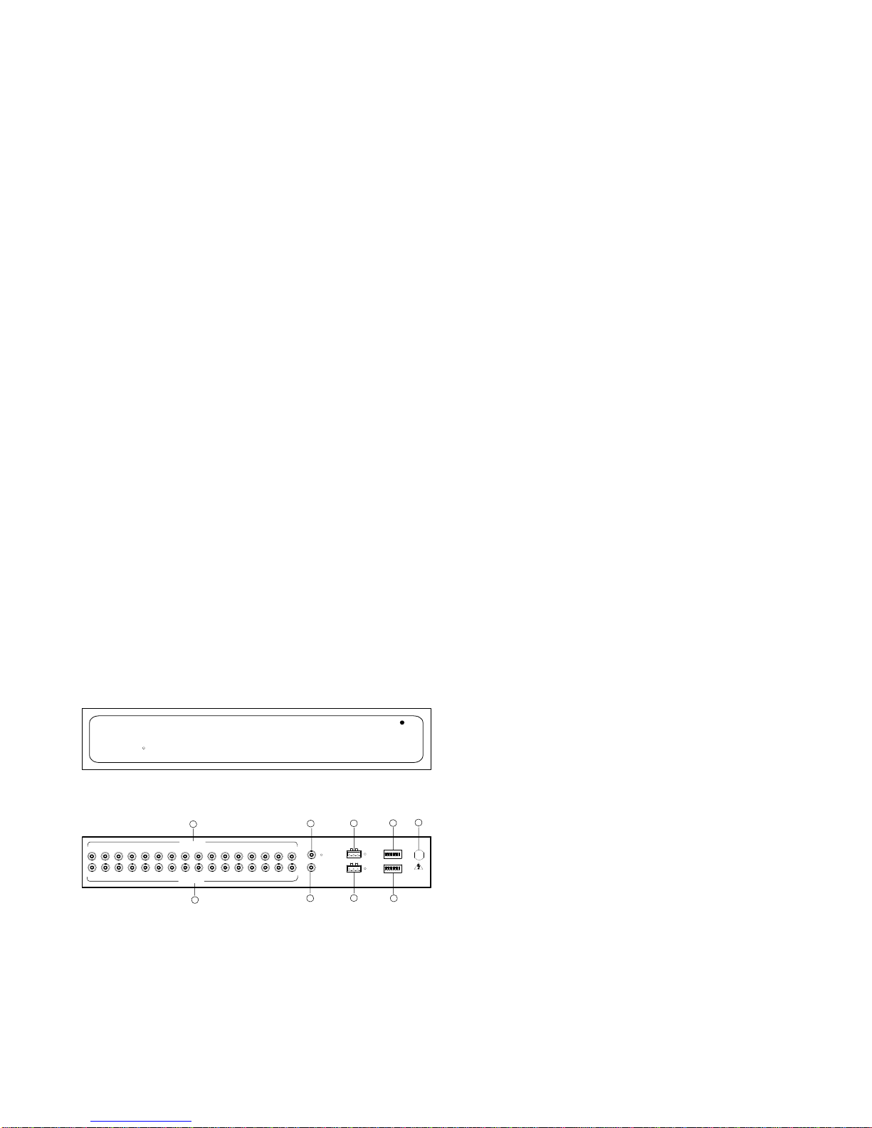
1.4 Panels
InfinovaR
POWER
CODE CONVERTER
Figure 1-1. V2414 Front Panel
IN
OUT
DATALINE
MANCHESTER
RS485
B S W
R+ GND R-
SW1
SW2
VIDEO OUTPUT
VIDEO INPUT
123456789
123456789
10 11 12 13 14 15 16
10 11 12 13 14 15 16
13579
2468
Figure 1-2. V2414 Rear Panel
① Video input (control command output)
② Video output
③ DATALINE Input
④ DATALINE Output
⑤ Manchester Input
⑥ RS-485 input
⑦ Baud Rate and protocol selection
⑧ Input protocol selection and address group
⑨ Power Cord
1.5 Maintenance
The V2414 series Up-the-coax Code Converters contain no user
serviceable parts inside and don’t need special maintenance. Make
sure that the unit is always been tightened and attached to a secure
base. Replace the connection cables showing wear or ageing since
they may seriously compromise the users’ safety.
2
Chapter II Installation and System
Connection
2.1 Installation
This installation should be made by qualified service personnel and
should conform to all local codes.
V2414 series Up-the-coax Code Converters are designed for indoor
use only. Two units of V2414 series may be mounted side by side in
one 19” EIA rack by using the Extension Flange, contact your
dealer or Infinova for details.
The overall dimensions for all versions of the V2414 series units
are as:
Height (top to bottom):1.74 inch (44.4mm)
Width (side to side): 9.0 inch (483mm)
Depth (front to back): 10.43 inch (265mm)
2.2 Power Connection
V2414 series Up-the-coax Code Converters are supplied with
embedded transformers, thus they can be connected to outlets for
primary power.
Warning:
Do not connect the V2414 series units to the primary power source
until ALL connections and switch settings have been completed and
verified.
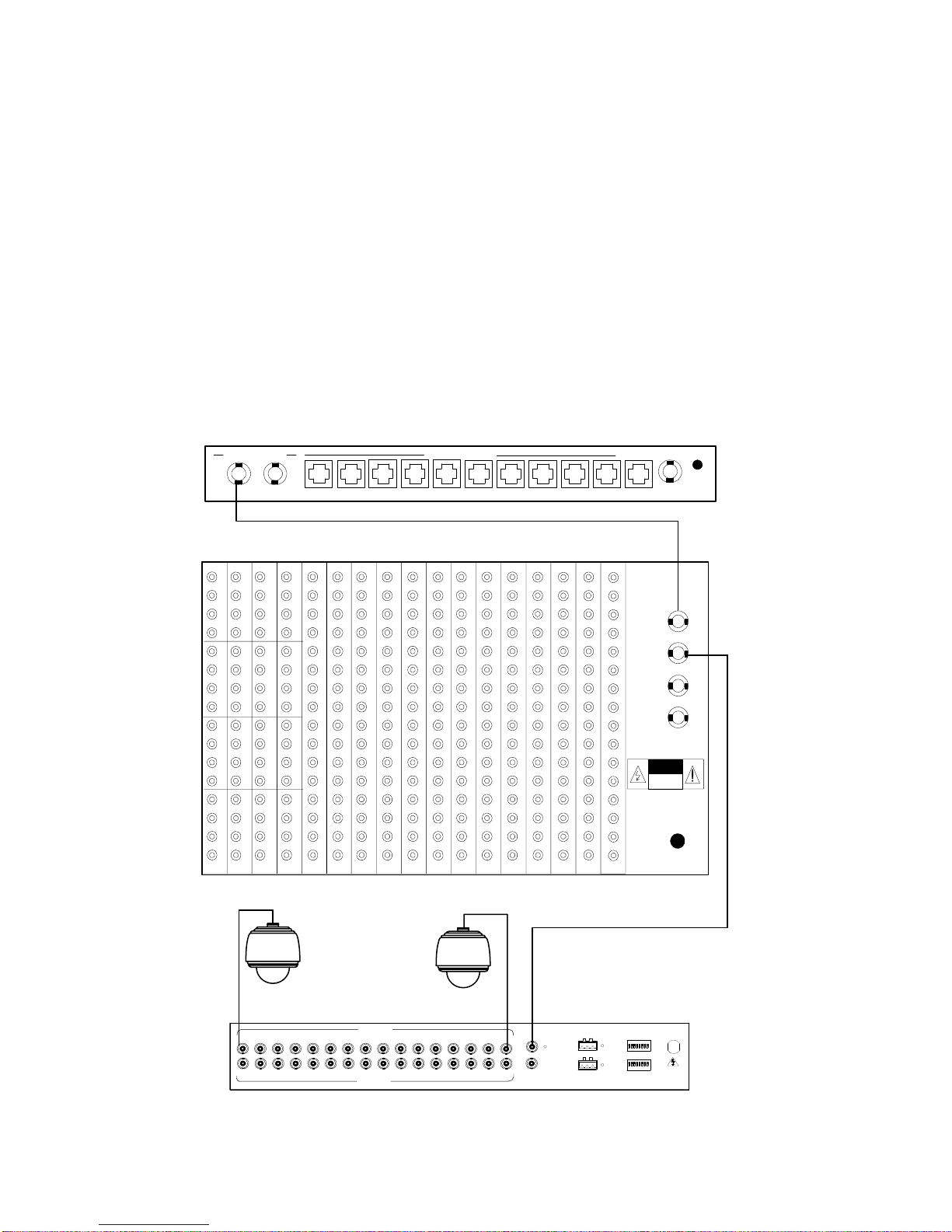
2.3 HSDL Connection
There is one DATALINE input/output on the V2414 real panel.
V2414 series Up-the-coax Code Converters convert HSDL from
Infinova series video matrix switchers (V2015, V2020, or V2040) to
16 Up-the-coax control signal outputs. Please refer to figure 2-1,
which demonstrates the connection between V2414 and V2040
matrix switcher.
V2040
1
2
3
4
5
6
7
8
9
10
11
12
13
14
15
16
177 161 145 129 113 97 81 65 49 33 17 1
DATALINE
IN
OUT
EXT
SYNC
IN
OUT
RISK OF
ELECTRIC
SHOCK
DONOT OPEN
POWER
D
A
T
A
B
U
F
F
E
R
DATA LINE RS232 PORTS ETHERNET PROG MON
12 1234567891011
Super Dome
V2414
Super Dome
IN
OUT
DATALINE
MANCHESTER
RS485
B S W
R+ GND R-
SW1
SW2
VIDEO OUTPUT
VIDEO INPUT
123456789
12 3 4 5 6 7 8 9 10 11 12 13 14 15 16
10 11 12 13 14 15 16
Figure 2-1. HSDL input

3
2.4 Manchester Connection
There is one Manchester input port on the V2414 real panel. V2414
series Up-the-coax Code Converters convert the Manchester codes
from Infinova series video matrix switchers (V2011, V2015) to 16
Up-the-coax control signal outputs. Please refer to figure 2-2, which
demonstrates the connection between V2414 and V2011 matrix
switcher.
B Connect a black code wire from the B terminal of the control
code source to the B terminal of V2414 series Up-the-coax Code
Converters.
WConnect a white code wire from the W terminal of the control
code source to the W terminal of V2414 series Up-the-coax Code
Converters.
S Connect one end of the shield cable to the S terminal of the
control code source. Connect the opposite end of the shield cable to
the S terminal of V2414 series Up-the-coax Code Converters.
Note: Use 18 AWG, shielded, 2-wire cable, Belden 8760 or
equivalent for code line connections.
IN
OUT
DATALINE
MANCHESTER
RS485
B S W
R+ GND R-
SW1
SW2
VIDEO OUTPUT
VIDEO INPUT
123456789
123456789
V2414
DOME DOME
10 11 12 13 14 15 16
10 11 12 13 14 15 16
MONITORS
RS232 PORTS
ALARMS RELAYS
12345678 9
2 4 6 8 10 12 14 16 18 20 22 24 26 28 30 32
13579111315171921232527
29 31
123456 87
NONCCM
CAMERAS
NONCCM
BWSBWSBWSBWS
MANCHESTER CODE
10111213141516
RS485 PORT
T+ T- GND
ETHERNET
1234
V2011
Figure 2-2. Manchester code input

4
2.5 RS-485 Connection
There is one RS-485 control code input on the V2414 real panel.
V2414 series Up-the-coax Code Converters convert RS-485 control
codes from Infinova series video matrix switchers (V2011, V2015)
to 16 Up-the-coax control signal outputs. Please refer to figure 2-3,
which demonstrates the connection between V2414 and V2015
matrix switcher.
V2015
VIDEO OUTPUTS
1 2 3 4 5 6 7 8 9 10 11 12 13 14 15 16
VIDEOINPUTS
1 2 3 4 5 6 7 8 9 10 11 12 13 14 15 16
17 18 19 20 21 22 23 24 25 26 27 28 29 30 31 3 2
33 34 35 36 37 38 39 40 41 42 43 44 45 46 47 4 8
49 50 51 52 53 54 55 56 57 58 59 60 61 62 63 6 4
65 66 67 68 69 70 71 72 73 74 75 76 77 78 79 8 0
1 2 3 4 5 6 7 8 9 10 11 12 15 16
13 14
BWSBWSBWSBWS
NO NC CM
ALARMS
CODE
RELAYS
PROG MON
RS232 PORTS ETHERNET
POWER
NCNO CM
RS485
T+ T - GND
123456
DATA LINE
Super Dome Super Dome
IN
OUT
DATALINE
MANCHESTER
RS485
B S W
R+ GND R-
SW1
SW2
VIDEO OUTPUT
VIDEO INPUT
12 3 4 5 6 7 8 9 10 11 12 13 14 15 16
12 3 4 5 6 7 8 9 10 11 12 13 14 15 16
V2414
Figure 2-3. RS-485 code input
2.6 Connection For Up-the-coax Control Signal
Output
There are 16 BNC video inputs on the V2414 real panel. These
video inputs could simultaneously be used for Up-the-coax control
signal outputs, to control over the dome cameras. Please refer to
figure 2-4.
Super Dome Super Dome
I
N
OU
T
DATALINE
MANCHESTER
RS485
B S W
R+ GND R-
SW1
SW2
VIDEO
OUTPUT
VIDEO
INPUT
123456789
1
01
11
21
31
41
51
6
123456789
1
01
11
21
31
41
51
6
V2414
Figure 2-4. Control super domes By V2414 outputs
2.7 Video Connection
2.7.1 Video Input Connection
The video inputs and control signals outputs of V2414 are
connected on one cable through BNC connectors. Connect the video
signals from the external dome camera to the BNC input terminal of
V2414. Please refer to figure 2-5.
Super Dome Super Dome
I
N
OU
T
DATALINE
MANCHESTER
RS485
B S W
R+ GND R-
SW1
SW2
VIDEO
OUTPUT
VIDEO
INPUT
123456789
1
01
11
21
31
41
51
6
123456789
1
01
11
21
31
41
51
6
V2414
Figure 2-5. Connecting Super Domes

5
To select appropriate control signal cables, please refer to the
following table:
Table 2-1. Coaxial Cable & Maximum Operating Distance
Cable Type Max. Operating Distance
RG59/U 750 ft (229 m)
RG6/U 1000 ft (305 m)
RG11/U 1500 ft (475m)
2.7.2 Video Output Connection
V2011 supports up to 16 video looping outputs. Please follow the
steps below to connect the monitor to the video looping output
terminal.
1. Properly install the monitors according to relevant manuals.
2. Connect the necessary coaxial video cables to the BNC output
ports located on V2414 rear panel.
IN
OUT
DATALINE
MANCHESTER
RS485
B S W
R+ GND R-
SW1
SW2
VIDEO OUTPUT
VIDEO INPUT
123456789
123456789
V2414
MONITOR MONITOR
10 11 12 13 14 15 16
10 11 12 13 14 15 16
Figure 2-6. Connecting Monitors
Chapter III System Setting and Operation
3.1 Setting for control protocols
3.1.1 DIP Switch
The DIP switch labeled SW2 is used to select input protocols and
camera address. The new settings could be effective only after
V2414 is powered off and restarted.
Please refer to the table 3-1 for details on SW2.
Table 3-1. DIP Switch SW2
1 2 3 4 5 6 7 8
Input Protocol Camera address
3.1.2 Select Input Protocol
V2414 series Up-the-coax Code Converters could receive HSDL
input, Manchester code input or RS-485 code input, but these three
inputs cannot simultaneously be selected to control the dome
cameras. The input protocol could be selected through position 1
and 2 of the DIP Switch. For details on the DIP setting, please refer
to table 3-2.
Table 3-2. Input Protocol Setting
(0 = OFF, 1 = ON)
DIP Switch
1 2 Select protocol type
0 0 HSDL
0 1 Manchester
1 0 RS-485
1 1 No
3.2 Protocol and Baud Rate Setting for RS-485
Input
3.2.1 DIP Switch
The DIP switch labeled SW1 is used to select the protocols and
baud rate for RS-485 inputs.
Please refer to the table 3-3 for details on SW1.
Table 3-3. DIP Switch SW1
1 2 3 4 5 6 7 8
Baud rate selection RS-485 protocol selection

6
3.2.2 Select Communication Protocol and Baud Rate
There are multiple control protocols optional for RS-485 input of
V2414 series Up-the-coax Code Converters, and there are multiple
types of baud rates for each control protocol. The baud rate could be
selected through positions 1-4 of DIP switch SW1; The protocol
could be selected through positions 5-8 of DIP switch SW1. Please
refer to table 3-4 for details on the setting of baud rate and protocol.
Table 3-4. Communication protocol and baud rate setting
(0 = OFF, 1 = ON)
Switch Position Switch Position
Baud
Rate 1 2 3 4 Protocol 5 6 7 8
1200 0 0 0 0 Pelco-P 0 0 0 0
2400 0 0 0 1 Pelco-D 0 0 0 1
4800 0 0 1 0 Infinova 0 0 1 0
9600 0 0 1 1
3.3 Camera Address Group
3.3.1 DIP Switch
The DIP switch labeled SW2 is used to select camera address.
Please refer to table 3-1 for details.
3.3.2 Camera Address Group Setting
One single V2414 unit could only 16 Up-the-coax control signals to
control the dome cameras. In the same system, multiple V2414 units
are required to control more than 16 dome cameras. The camera
address could be selected through positions 3-8 of DIP SW2. Please
refer to table 3-4 for details on the setting of camera addresses.
Note: The CAM ID numbers may vary differently because different
matrix switchers have different video inputs when controlling
V2414. Please refer to the corresponding manuals for details.
Table 3-5. Camera Address Group Setting
DIP Switch SW2
Camera Group 3 4 5 6 7 8
1-16 0 0 0 0 0 0
17-32 0 0 0 0 0 1
33-48 0 0 0 0 1 0
49-64 0 0 0 0 1 1
65-80 0 0 0 1 0 0
81-96 0 0 0 1 0 1
97-112 0 0 0 1 1 0
113-128 0 0 0 1 1 1
129-144 0 0 1 0 0 0
145-160 0 0 1 0 0 1
161-176 0 0 1 0 1 0
177-192 0 0 1 0 1 1
193-208 0 0 1 1 0 0
DIP Switch SW2
Camera Group 3 4 5 6 7 8
209-224 0 0 1 1 0 1
225-240 0 0 1 1 1 0
241-256 0 0 1 1 1 1
257-272 0 1 0 0 0 0
273-288 0 1 0 0 0 1
289-304 0 1 0 0 1 0
305-320 0 1 0 0 1 1
321-336 0 1 0 1 0 0
337-352 0 1 0 1 0 1
353-368 0 1 0 1 1 0
369-384 0 1 0 1 1 1
385-400 0 1 1 0 0 0
401-416 0 1 1 0 0 1
417-432 0 1 1 0 1 0
433-448 0 1 1 0 1 1
449-464 0 1 1 1 0 0
465-480 0 1 1 1 0 1
481-496 0 1 1 1 1 0
497-512 0 1 1 1 1 1
513-528 1 0 0 0 0 0
529-544 1 0 0 0 0 1
545-560 1 0 0 0 1 0
561-576 1 0 0 0 1 1
577-592 1 0 0 1 0 0
593-608 1 0 0 1 0 1
609-624 1 0 0 1 1 0
625-640 1 0 0 1 1 1
641-656 1 0 1 0 0 0
657-672 1 0 1 0 0 1
673-688 1 0 1 0 1 0
689-704 1 0 1 0 1 1
705-720 1 0 1 1 0 0
721-736 1 0 1 1 0 1
737-752 1 0 1 1 1 0
753-768 1 0 1 1 1 1
769-784 1 1 0 0 0 0
785-800 1 1 0 0 0 1
801-816 1 1 0 0 1 0
817-832 1 1 0 0 1 1
833-848 1 1 0 1 0 0
849-864 1 1 0 1 0 1
865-880 1 1 0 1 1 0
881-896 1 1 0 1 1 1
897-912 1 1 1 0 0 0
913-928 1 1 1 0 0 1
929-944 1 1 1 0 1 0
945-960 1 1 1 0 1 1
961-976 1 1 1 1 0 0
977-992 1 1 1 1 0 1
993-1008 1 1 1 1 1 0
1009-1024 1 1 1 1 1 1
Note: The camera address numbers for Manchester protocol reaches
a maximum of 64, which could be divided to 4 groups and each
group includes 16 outputs; the camera address numbers for PELCO
P/D protocol reaches a maximum of 256, which could be divided to
16 groups; the camera address numbers for INFINOVA protocol
reaches a maximum of 128, which could be divided to 8 groups; and
the camera address numbers for DATALINE reaches a maximum of
1024, which could be divided to 64 groups.
7
3.4 Dome Control Operations
Up-the-coax control signals could be outputted to control dome
cameras after the V2414 converter is connected and the relative
setting is finished. For details on the functions and operations of the
dome camera or receiver, please refer to the following contents of
this section. For details on other operations, please refer to the
corresponding manuals.
Note: To make the new setting valid, it is necessary to re-power the
super dome after changing the setting of DIP Switch.
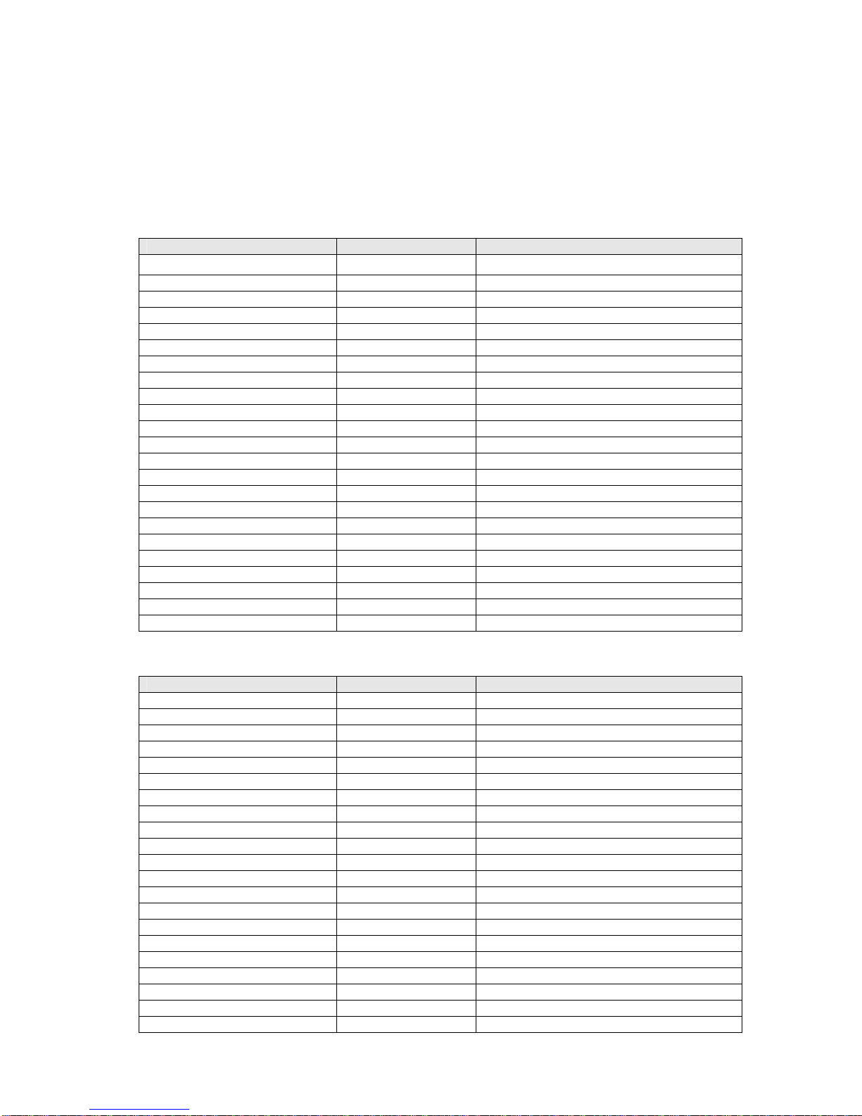
3.4.1 INFINOVA Protocol Input
1. Input through Keyboard
Function Keyboard State Operation
SET PRESET PROGRAM 1-32, 35-127 + SHOT
CALL PRESET OPERATE 1-32, 35-127 + SHOT
PLIP 180°OPERATE 33 + SHOT
HOME POSITION OPERATE 34 + SHOT
ENTER MENU PROGRAM 65/95 + SHOT
CALL AUTOSCAN OPERATE 99 + SHOT
CLEAR SCREEN PROGRAM 67 + SHOT
REMOTE RESET PROGRAM 68 + SHOT
RESUME ALARM OPERATE 64 + SHOT
B/W TO COLOR OPERATE 88 + SHOT
COLOR TO B/W OPERATE 89 + SHOT
SET PATTERN 1 PROGRAM 70 + SHOT
SET PATTERN 2 PROGRAM 71 + SHOT
SET PATTERN 3 PROGRAM 72 + SHOT
SET PATTERN 4 PROGRAM 73 + SHOT
SAVE PATTERN PROGRAM 70/71/72/73 + SHOT
CALL PATTERN 1 OPERATE 70 + SHOT
CALL PATTERN 2 OPERATE 71 + SHOT
CALL PATTERN 3 OPERATE 72 + SHOT
CALL PATTERN 4 OPERATE 73 + SHOT
SET AUTOPAN OPERATE 92 + SHOT
SAVE AUTOPAN OPERATE 93 + SHOT
CALL AUTOPAN OPERATE 98 + SHOT
2. Input through Matrix Switcher
Function Keyboard State Operation
SET PRESET PROGRAM 1-32, 35-127 + SHOT
CALL PRESET OPERATE 1-32, 35-58, 74-127 + SHOT
PLIP 180°OPERATE 33 + SHOT
HOME POSITION OPERATE 34 + SHOT
ENTER MENU PROGRAM 65/95 + SHOT
CALL AUTOSCAN OPERATE 99 + SHOT
CLEAR SCREEN PROGRAM 67 + SHOT
REMOTE RESET PROGRAM 68 + SHOT
RESUME ALARM OPERATE 64 + SHOT
B/W TO COLOR OPERATE 88 + SHOT
COLOR TO B/W OPERATE 89 + SHOT
SET PATTERN 1 PROGRAM 70 + SHOT
SET PATTERN 2 PROGRAM 71 + SHOT
SET PATTERN 3 PROGRAM 72 + SHOT
SAVE PATTERN PROGRAM 70/71/72 + SHOT
CALL PATTERN 1 OPERATE 70 + SHOT
CALL PATTERN 2 OPERATE 71 + SHOT
CALL PATTERN 3 OPERATE 72 + SHOT
SET AUTOPAN OPERATE 92 + SHOT
SAVE AUTOPAN OPERATE 93 + SHOT
CALL AUTOPAN OPERATE 98 + SHOT
8
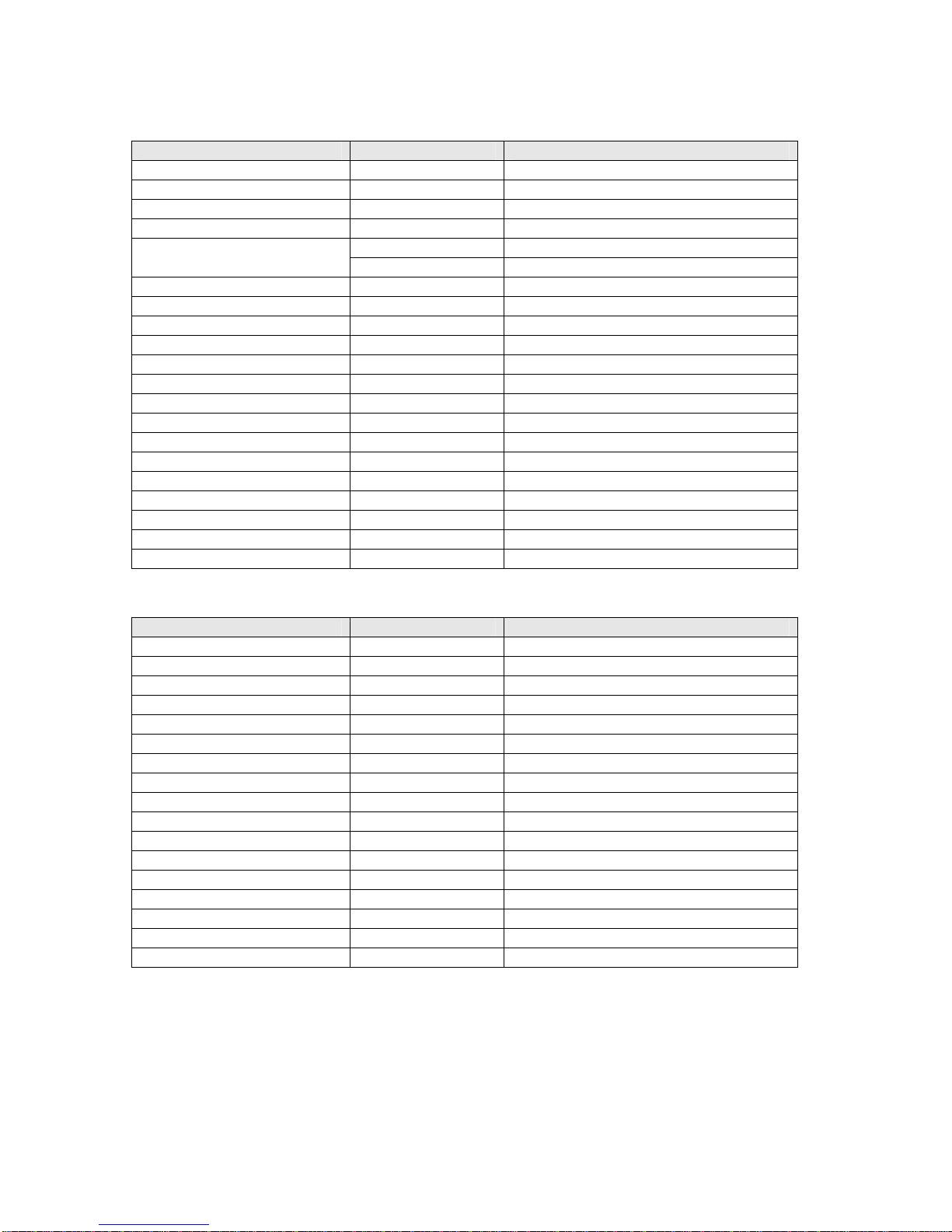
3.4.2 PELCO-D Protocol Input
1. Input through Keyboard
Function Keyboard State Operation
SET PRESET PROGRAM 1-32, 35-127 + SHOT
CALL PRESET OPERATE 1-32,35-127 + SHOT
PLIP 180°OPERATE 33 + SHOT
HOME POSITION OPERATE 34 + SHOT
PROGRAM 66/95 + SHOT
ENTER MENU OPERATE 66 + SHOT
CALL AUTOSCAN OPERATE 99 + SHOT
CLEAR SCREEN PROGRAM 67 + SHOT
REMOTE RESET PROGRAM 68 + SHOT
RESUME ALARM OPERATE 64 + SHOT
B/W TO COLOR OPERATE 88 + SHOT
COLOR TO B/W OPERATE 89 + SHOT
SET PATTERN 1 PROGRAM 70 + SHOT
SET PATTERN 2 PROGRAM 71 + SHOT
SET PATTERN 3 PROGRAM 72 + SHOT
SET PATTERN 4 PROGRAM 73 + SHOT
SAVE PATTERN PROGRAM 69 + SHOT
CALL PATTERN 1 OPERATE 70 + SHOT
CALL PATTERN 2 OPERATE 71 + SHOT
CALL PATTERN 3 OPERATE 72 + SHOT
CALL PATTERN 4 OPERATE 73 + SHOT
2. Input through Matrix Switcher
Function Keyboard State Operation
SET PRESET PROGRAM 1-32, 35-127 + SHOT
CALL PRESET OPERATE 1-32, 35-58, 74-127 + SHOT
PLIP 180°OPERATE 33 + SHOT
HOME POSITION OPERATE 34 + SHOT
ENTER MENU PROGRAM 66/95 + SHOT
CALL AUTOSCAN OPERATE 99 + SHOT
B/W TO COLOR OPERATE 88 + SHOT
COLOR TO B/W OPERATE 89 + SHOT
SET PATTERN 1 OPERATE 59 + SHOT
SET PATTERN 2 OPERATE 61 + SHOT
SET PATTERN 3 OPERATE 63 + SHOT
SET PATTERN 4 OPERATE 65 + SHOT
SAVE PATTERN OPERATE 66 + SHOT
CALL PATTERN 1 OPERATE 60 + SHOT
CALL PATTERN 2 OPERATE 62 + SHOT
CALL PATTERN 3 OPERATE 64 + SHOT
CALL PATTERN 4 OPERATE 67 + SHOT

9
3.4.3 PELCO-P Protocol Input
1. Input through Keyboard
Function Keyboard State Operation
SET PRESET PROGRAM 1-32, 35-127 + SHOT
CALL PRESET OPERATE 1-32, 35-127 + SHOT
PLIP 180°OPERATE 33 + SHOT
HOME POSITION OPERATE 34 + SHOT
PROGRAM 66/95 + SHOT
ENTER MENU OPERATE 66 + SHOT
CALL AUTOSCAN OPERATE 99 + SHOT
CLEAR SCREEN PROGRAM 67 + SHOT
REMOTE RESET PROGRAM 68 + SHOT
RESUME ALARM OPERATE 64 + SHOT
B/W TO COLOR OPERATE 88 + SHOT
COLOR TO B/W OPERATE 89 + SHOT
SET PATTERN 1 PROGRAM 70 + SHOT
SET PATTERN 2 PROGRAM 71 + SHOT
SET PATTERN 3 PROGRAM 72 + SHOT
SET PATTERN 4 PROGRAM 73 + SHOT
SAVE PATTERN PROGRAM 69 + SHOT
CALL PATTERN 1 OPERATE 70 + SHOT
CALL PATTERN 2 OPERATE 71 + SHOT
CALL PATTERN 3 OPERATE 72 + SHOT
CALL PATTERN 4 OPERATE 73 + SHOT
2. Input through Matrix Switcher
Function Keyboard State Operation
SET PRESET PROGRAM 1-32, 35-127 + SHOT
CALL PRESET OPERATE 1-32, 35-58, 74-127 + SHOT
PLIP 180°OPERATE 33 + SHOT
HOME POSITION OPERATE 34 + SHOT
ENTER MENU PROGRAM 66/95 + SHOT
CALL AUTOSCAN OPERATE 72/99 + SHOT
B/W TO COLOR OPERATE 88 + SHOT
COLOR TO B/W OPERATE 89 + SHOT
SET PATTERN 1 OPERATE 59 + SHOT
SET PATTERN 2 OPERATE 61 + SHOT
SET PATTERN 3 OPERATE 63 + SHOT
SET PATTERN 4 OPERATE 65 + SHOT
SAVE PATTERN OPERATE 66 + SHOT
CALL PATTERN 1 OPERATE 60 + SHOT
CALL PATTERN 2 OPERATE 62 + SHOT
CALL PATTERN 3 OPERATE 64 + SHOT
CALL PATTERN 4 OPERATE 67 + SHOT

10
3.4.4 MANCHESTER Protocol Input
1. Input through Keyboard
Function Keyboard State Operation
SET PRESET PROGRAM 1-32, 35-63 + SHOT
CALL PRESET OPERATE 1-32, 35-62 + SHOT
PLIP 180°OPERATE 65 + SHOT
HOME POSITION PROGRAM 64 + SHOT
ENTER MENU PROGRAM 65 + SHOT
CALL AUTOSCAN OPERATE 66 + SHOT
CLEAR SCREEN PROGRAM 67 + SHOT
REMOTE RESET PROGRAM 68 + SHOT
RESUME ALARM OPERATE 64 + SHOT
SET PATTERN 1 PROGRAM 70 + SHOT
SET PATTERN 2 PROGRAM 71 + SHOT
SET PATTERN 3 PROGRAM 72 + SHOT
SAVE PATTERN PROGRAM 69 + SHOT
CALL PATTERN 1 OPERATE 70 + SHOT
CALL PATTERN 2 OPERATE 71 + SHOT
CALL PATTERN 3 OPERATE 72 + SHOT
2. Input through Matrix Switcher
Function Keyboard State Operation
SET PRESET PROGRAM 1-32, 35-63 + SHOT
CALL PRESET OPERATE 1-32, 35-60 + SHOT
PLIP 180°OPERATE 65 + SHOT
HOME POSITION PROGRAM 64 + SHOT
ENTER MENU PROGRAM 65 + SHOT
CALL AUTOSCAN OPERATE 66 + SHOT
CLEAR SCREEN PROGRAM 67 + SHOT
REMOTE RESET PROGRAM 68 + SHOT
SET PATTERN 1 PROGRAM 70 + SHOT
SET PATTERN 2 PROGRAM 71 + SHOT
SET PATTERN 3 PROGRAM 72 + SHOT
SAVE PATTERN PROGRAM 69 + SHOT
CALL PATTERN 1 OPERATE 70 + SHOT
CALL PATTERN 2 OPERATE 71 + SHOT
CALL PATTERN 3 OPERATE 72 + SHOT

11
3.4.5 Matrix Switcher DATALINE Input
Function Keyboard State Operation
SET PRESET PROGRAM 1-32, 35-127 + SHOT
CALL PRESET OPERATE 1-32, 35-127 + SHOT
PLIP 180°OPERATE 33/65 + SHOT
OPERATE 34 + SHOT
HOME POSITION PROGRAM 64 + SHOT
PROGRAM 65/95 + SHOT
ENTER MENU OPERATE 95 + SHOT
CALL AUTOSCAN OPERATE 66 + SHOT
CLEAR SCREEN OPERATE 67 + SHOT
REMOTE RESET PROGRAM 68 + SHOT
RESUME ALARM OPERATE 64 + SHOT
B/W TO COLOR OPERATE 68/88 + SHOT
COLOR TO B/W OPERATE 69/89 + SHOT
SET PATTERN 1 PROGRAM 70 + SHOT
SET PATTERN 2 PROGRAM 71 + SHOT
SET PATTERN 3 PROGRAM 72 + SHOT
SET PATTERN 4 PROGRAM 73 + SHOT
SAVE PATTERN PROGRAM 69 + SHOT
CALL PATTERN 1 OPERATE 70 + SHOT
CALL PATTERN 2 OPERATE 71 + SHOT
CALL PATTERN 3 OPERATE 72 + SHOT
CALL PATTERN 4 OPERATE 73 + SHOT
PROGRAM 66 + SHOT
SET AUTOPAN OPERATE 92 + SHOT
PROGRAM 67 + SHOT
SAVE AUTOPAN OPERATE 93 + SHOT
CALL AUTOPAN OPERATE 64/98 + SHOT

12
Appendix I Specifications
General
HSDL: Input/output, BNC connectors
RS-485: Plug-in terminal connector, triple-shield
Manchester: Plug-in terminal connector, triple-shield
Electrical
Voltage: 120VAC/60Hz; 230VAC/50Hz
Power consumption: 8W
Mechanical
Dimension: 1.74〞H×19.0〞W×10.43〞D
44.4mm (H)×483mm (W)×265mm (D)
Weight: 4.4 lb (2.0 kg)
Mount: Rack mount, desk, or wall mount optional
Environment
Temperature: 0℃~40℃(32℉~104℉)
Moisture: 0~90﹪RH(Non-condensing)

13
Appendix II Cable Diameter Calculation and Lightning & Surge Protection
Relation between 24VAC Cable Diameter and Transmission Distance
In general, the maximum allowable voltage loss rate is 10% for AC-powered devices. The table below shows the
relationship between transmission power and maximum transmission distance under a certain specified cable diameter, on
condition that the 24VAC voltage loss rate is below 10%. According to the table, if a device rated at 50W is installed
17-meter away from the transformer, the minimum cable diameter shall be 0.8000mm. A lower diameter value tends to
cause voltage loss and even system instability.
0.8000 1.000 1.250 2.000
10 283 (86) 451 (137) 716 (218) 1811 (551)
20 141 (42) 225 (68) 358 (109) 905 (275)
30 94 (28) 150 (45) 238 (72) 603 (183)
40 70 (21) 112 (34) 179 (54) 452 (137)
50 56 (17) 90 (27) 143 (43) 362 (110)
60 47 (14) 75 (22) 119 (36) 301 (91)
70 40 (12) 64 (19) 102 (31) 258 (78)
80 35 (10) 56 (17) 89 (27) 226 (68)
90 31 (9) 50 (15) 79 (24) 201 (61)
100 28 (8) 45 (13) 71 (21) 181 (55)
110 25 (7) 41 (12) 65 (19) 164 (49)
120 23 (7) 37 (11) 59 (17) 150 (45)
130 21 (6) 34 (10) 55 (16) 139 (42)
140 20 (6) 32 (9) 51 (15) 129 (39)
150 18 (5) 30 (9) 47 (14) 120 (36)
160 17 (5) 28 (8) 44 (13) 113 (34)
170 16 (4) 26 (7) 42 (12) 106 (32)
180 15 (4) 25 (7) 39 (11) 100 (30)
190 14 (4) 23 (7) 37 (11) 95 (28)
200 14 (4) 22 (6) 35 (10) 90 (27)
Distance (ft / m)
Power
(
W
)
Diameter (mm)

14
Lightning & Surge Protection
The product adopts multi-level anti-lightning and anti-surge technology integrated with gas discharge tube, power resistor
and TVS tube. The powerful lightning and surge protection barrier effectively avoids product damage caused by various
pulse signals with power below 4kV, including instantaneous lightning, surge and static. However, for complicated
outdoor environment, refer to instruction below for lightning and surge protection:
zThe product features with dedicated earth wire, which must be firmly grounded. As for surveillance sites beyond the
effective protection scope, it’s necessary to erect independent lightening rods to protect the security devices. It’s
recommended to separate the lightning rod from the mounting pole, placing the rod on an independent pole, as shown
in the figure below. If the product has to be installed on the same pole or pedestal for lightning rod, there should be
strict insulation between the video cable BNC terminal, power cable, control cable and the standing pole of the
lightning rod.
zFor suburb and rural areas, it’s recommended to adopt direct burial for the transmission cables. Overhead wiring is
prohibited, because it’s more likely to encounter lightning strike. Use shielded cables or thread the cables through metal
tubes for burial, thus to ensure the electric connection to the metal tube. In case it’s difficult to thread the cable through
the tube all the way, it’s acceptable to use tube-threaded cables only at both ends of the transmission line, yet the length
in burial should be no less than 15 meters. The cable sheath and the tube should be connected to the lightning -proof
grounding device.
zAdditional high-power lightning-proof equipment and lightning rods should be installed for strong thunderstorm or
high induced voltage areas (such as high-voltage substation).
zThe lightning protection and grounding for outdoor devices and wires should be designed in line with the actual
protection requirement, national standards and industrial standards.
zThe system should perform equipotential grounding by streaming, shielding, clamping and earthing. The grounding
device must meet anti-interference and electric safety requirements. There should be no short-circuiting or hybrid
junction between the device and the strong grid. Make sure there’s a reliable grounding system, with grounding
resistance below 4Ω(below 10Ωfor high soil resistivity regions). The cross-sectional area of the earthing conductor
should be no less than 25mm².
This manual suits for next models
1
Table of contents
Popular Media Converter manuals by other brands


Moxa Technologies
Moxa Technologies NPort 5600-8-DT Quick installation guide

Hengstler
Hengstler AC 58 SUCOnet installation instructions

Avid Technology
Avid Technology Pro Tools MTRX Operation guide

Ocean Matrix
Ocean Matrix OMX-02MXSI0001 INSTALLATION & SPECIFICATIONS

Zetex
Zetex ZXLD1321EV2 Uesr guide

Patton electronics
Patton electronics 2020N user manual