Inflight Fitness CT-CCO User manual

CT-CCO CABLE CROSS


CCO ASSEMBLY INSTRUCTIONS
IMPORTANT NOTICES
Read all warning labels, the instruction placard and this manual before
attempting to use this machine. Always consult your physician and an
exercise professional before beginning any exercise program/regimen.
Before any test or use check for proper assembly of the machine including
(but not limited to): bolts and other hardware fastened properly, cables in
pulley grooves and routed correctly. For safety use the top weight only for
the first machine movement.
Maintain your machine in good working order by following the maintenance
schedule provided on the equipment.
It is strongly recommended that a qualified dealer assemble this
Cable Cross machine
Should there be any question during assembly contact your authorized Inflight
Fitness dealer or call direct to 714 821 4177.
Before beginning assembly read this instruction manual thoroughly. Unpack and
verify all parts and hardware quantities against the parts and hardware lists.
Follow the assembly steps in sequence. Failure to follow the order of assembly
will result in disassembly later and possible damage to the machine components.
The 3/8” nuts provided with this machine are “centerlocking”. They provide a
more secure assembly than nylon locking nuts. Please note they do require
more force to tighten than nylon locking nuts.
1

CCO PARTS AND HARDWARE
HARDWARE
DESCRIPTION QUANTITY
Bolts
3/8” x 8 ½” 8
3/8” x 5” 4
3/8” x 4 ¾” 12
3/8” x 4 ¼” 2
3/8” x 4” 2`
3/8” x 2 ¾” 6
3/8” x 2 ½” 6
3/8” x 2 ¼” 4
3/8” x 2” 2
3/8” x 1 ¾” 12
3/8” x 1 ½” 2
Washers and Nuts
3/8” Curved Washers 28
3/8” Flat Washers 80
3/8” Nuts – Center-locking 52
2

CCO PARTS AND HARDWARE
PARTS
WHITE / PLATINUM FRAME PARTS
Loop Upright (2)
Bottom Bracket (2) Base Tube (2)
BLACK FRAME PARTS
Top Beam (2) Pulley Carriage (2) Upper Pulley Bracket (2)
Handle (4) Round Cable Retainers (4)
Stabilizer (2) Center Tube Connector Tubes (2)
CABLES AND PULLEYS
CLM Cable 4 ½” Pulleys (11)
MISCELLANEOUS
Guide Rods (4) Lube Weight Stack Cushions (4)
Slider Tube (2) Exercise Handles (2) Instruction Placard
Weight Labels Manual Top Weights (2)
10-5# Weight Plates 20-10# Weight Plates 10-15# Weight Plates
Weight Selector Stem (2) Weight Pins with Lanyard (2) Cables (2)
3

CCO ASSEMBLY INSTRUCTIONS
PRE - ASSEMBLY ONLY
A. Assemble the two Connector Tubes to the Center Tube with 4 – 3/8” x 2 ¼”
bolts, 8 –3/8” flat washers, and 4 – nuts. Do not fully tighten at this time.
B. Slide a Pulley Carriage onto each chrome Slider Tube. Orient the pulley
Carriage with the pop pin nearer the welded U-Bracket.
C. Attach a rubber stop (four total) to each side of the chrome Slider tube at the
second cross-drilled hole from the bottom using 1 – 3/8” x 2 ¼” bolts, 2 – 3/8”
flat washers and 1 – 3/8” nuts. Tighten these bolts.
D. Attach the Bottom Brackets to the Base Tubes using 2 – 3/8” x 5” bolts and 4
- 3/8” flat washers and 2 - 3/8” nuts. Do not tighten completely.
E. Attach the Chin-up bar to the Center Tube Ass’y from Step A. using 2 – 4”
bolts, 2 – 2 ½” Bolts, 4 – curved washers, 4 – washers, and 4 – nuts. Tighten
these bolts.
Note:
Exercise extreme caution when assembling the Center
Tube and Top Beams. A ladder or sturdy, stable chair is
advised when assembling high parts.
Step L. is a two person task.
Remember to lift the assemblies when maneuvering to
fit. This will protect the rubber feet.
4
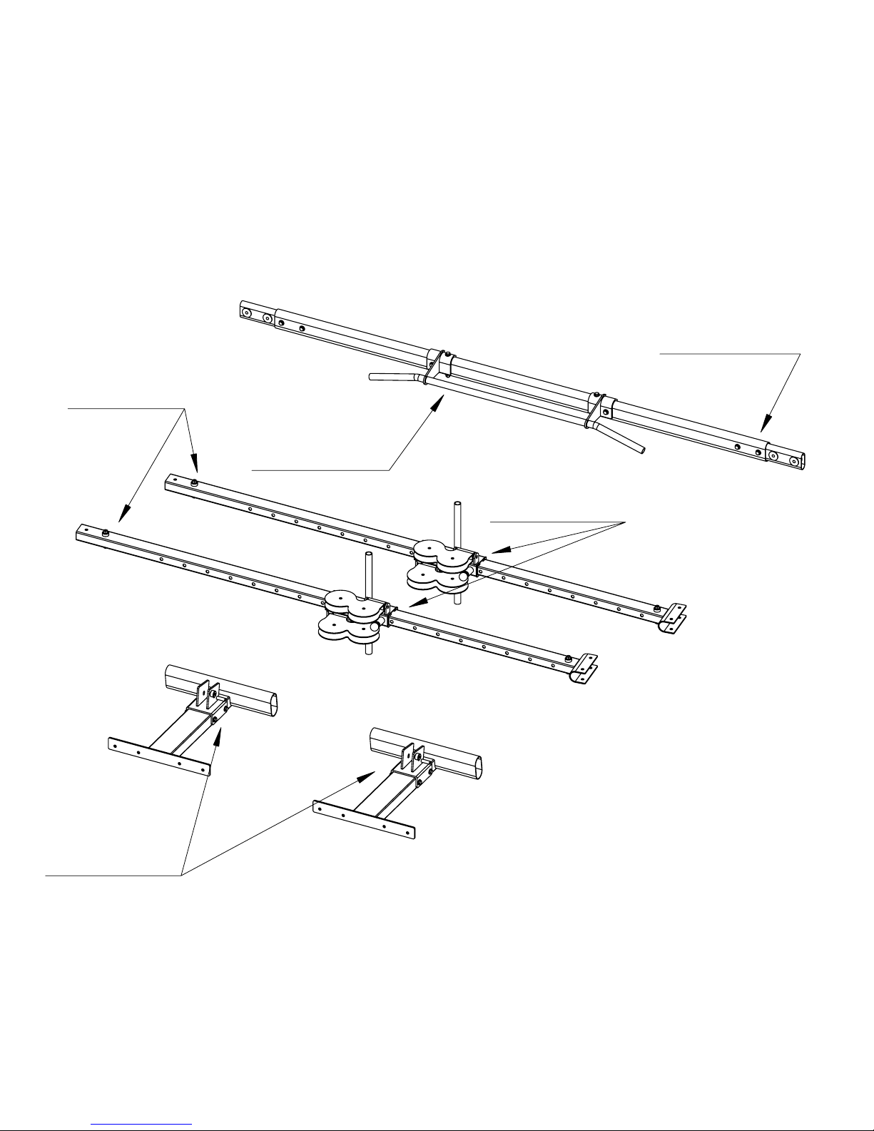
1 - Center Tube
2 - Connector Tubes
4 - 2 1/4" Bolts
8 - Flat Washers
4 - Nuts
2 - Chrome Tubes
2 - Pulley Carriages
2 - Base Tubes
2 - Bottom Brackets
4 - 5" bolts
8 - Flat Washers
4 - Nuts
4 - Rubber Stops
2 - 2 3/4" Bolts
4 - Flat Washers
2 - Nuts
5
A
B
C
D
1 - Chin-up Bar
2 - 4" Bolts
2 - 2 1/2" Bolts
4 - Curved Washers
4 - Washers
4 - Nuts
E

CCO ASSEMBLY INSTRUCTIONS
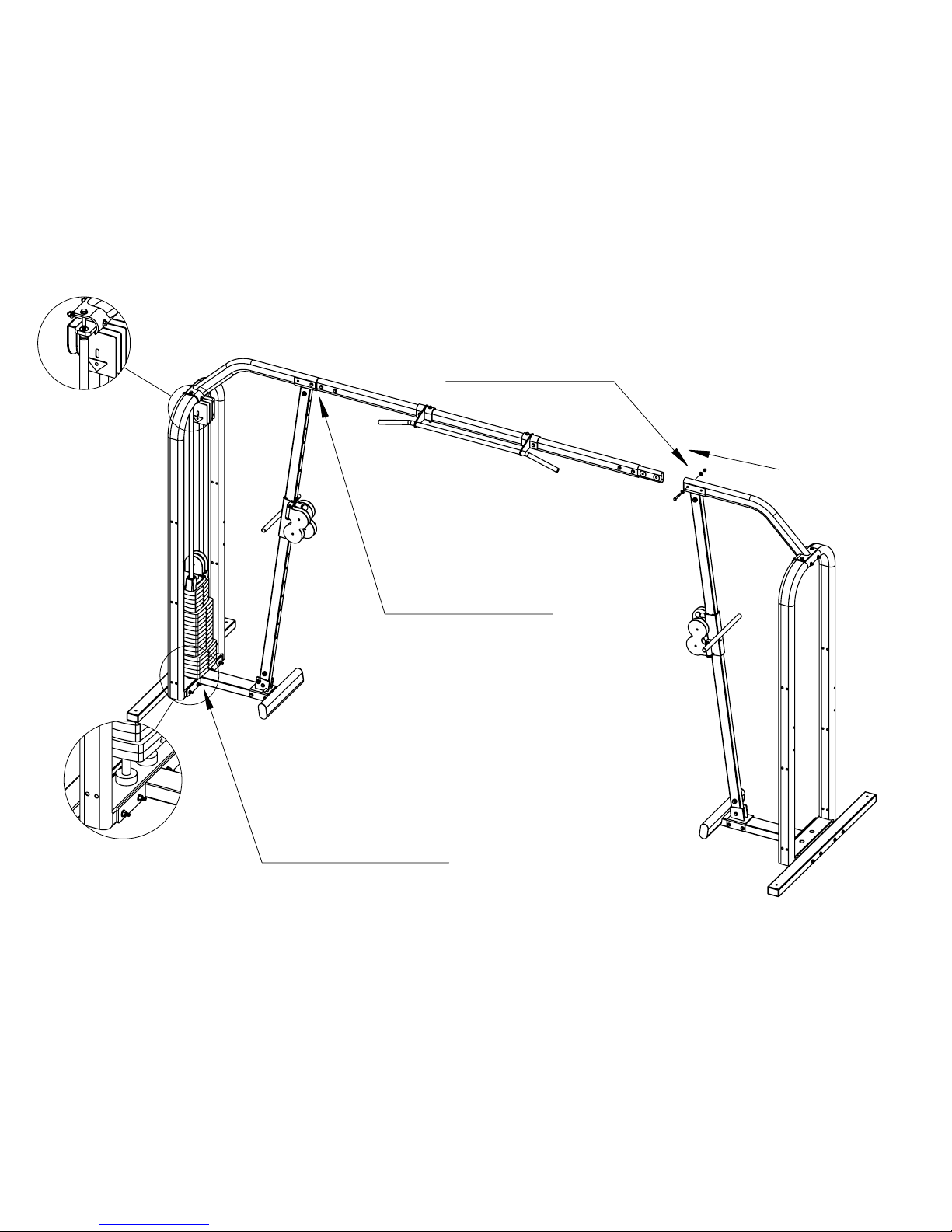
MAIN STRUCTURE ASSEMBLY
BUILD TWO OF THE ASSEMBLIES DETAILED IN STEPS F- I
F. Attach the Rear Stabilizer and Base Ass’y (from Step D.) to the Loop Upright
using 4 – 3/8” x 8 ½” bolts, 8 – 3/8” flat washers and 4 - 3/8” nuts.
G. Place the bottom of the chrome Slider Tube Ass’y (from Steps B. and C.)
within the Bottom Bracket. Bolt the bottom of the Slider Tube to the Bottom
Bracket using 1 – 3/8” x 2 ½” bolt, 2 – 3/8” flat washers and 1 – 3/8” nut.
Tighten this bolt.
H. Place a Top Beam within the “U”- bracket at the top of the chrome Slider
Tube Ass’y. Fasten the Top Beam to the Loop Upright using 2 – 3/8” x 4 ¾”
bolts, 4 – 3/8” curved washers and 2 – 3/8” nuts. Do not tighten completely.
Also install 2 – 2 ¾” bolts and 2 – washers through the top holes of the Top
Beam bracket and Loop Upright to ensure alignment. .
I. Then fasten the other end of the Top Beam to the chrome Slide Tube Ass’y
using 1 – 2 ½” bolt and 1 – washer in the holes closest to the end of the Top
beam. Insert 1 – 4 ¼” bolt and 1 – washer in the other holes. Do not install a
washer and nut on the other side of these bolts. They will be fastened at
Steps K. and L.
Tighten the bolts installed at Steps D. and F.
Remove the black end cap in the end of the Top Beam
Note:
Before continuing, place one of the assemblies exactly
where it is to remain. After further assembly it will be
unmovable.
Place the other assembly approximately 14 feet away as
measured from the back of one Rear Stabilizer to the
other. The finished Cable Cross will measure 13 feet 3
inches long by 4 feet wide.
6

1 - Loop Upright
1 - Stabilizer Ass'y
1 - Base Ass'y
4 - 8 1/2" Bolt
8 - Washers
4 - Nuts
Slider Ass'y
1 - 2 1/2" Bolt
2 - Washers
1 - Nut
1 - Top Beam
2 - 4 3/4" Bolts
2 - 2 3/4" Bolts
4 - Curved Washers
2 - Washers
2 - Nuts
1 - 2 1/2" Bolt
1 - 4 1/4" Bolt
2 - Washers
F (x 2)
G (x 2)
H (x 2)
I (x 2)
REMOVE BLACK END CAP
7
BUILD TWO FRAME ASSEMBLIES
AND POSITION FACING EACH OTHER AT
APPROXIMTELY 14 FEET OVERALL LENGTH

CCO ASSEMBLY INSTRUCTIONS
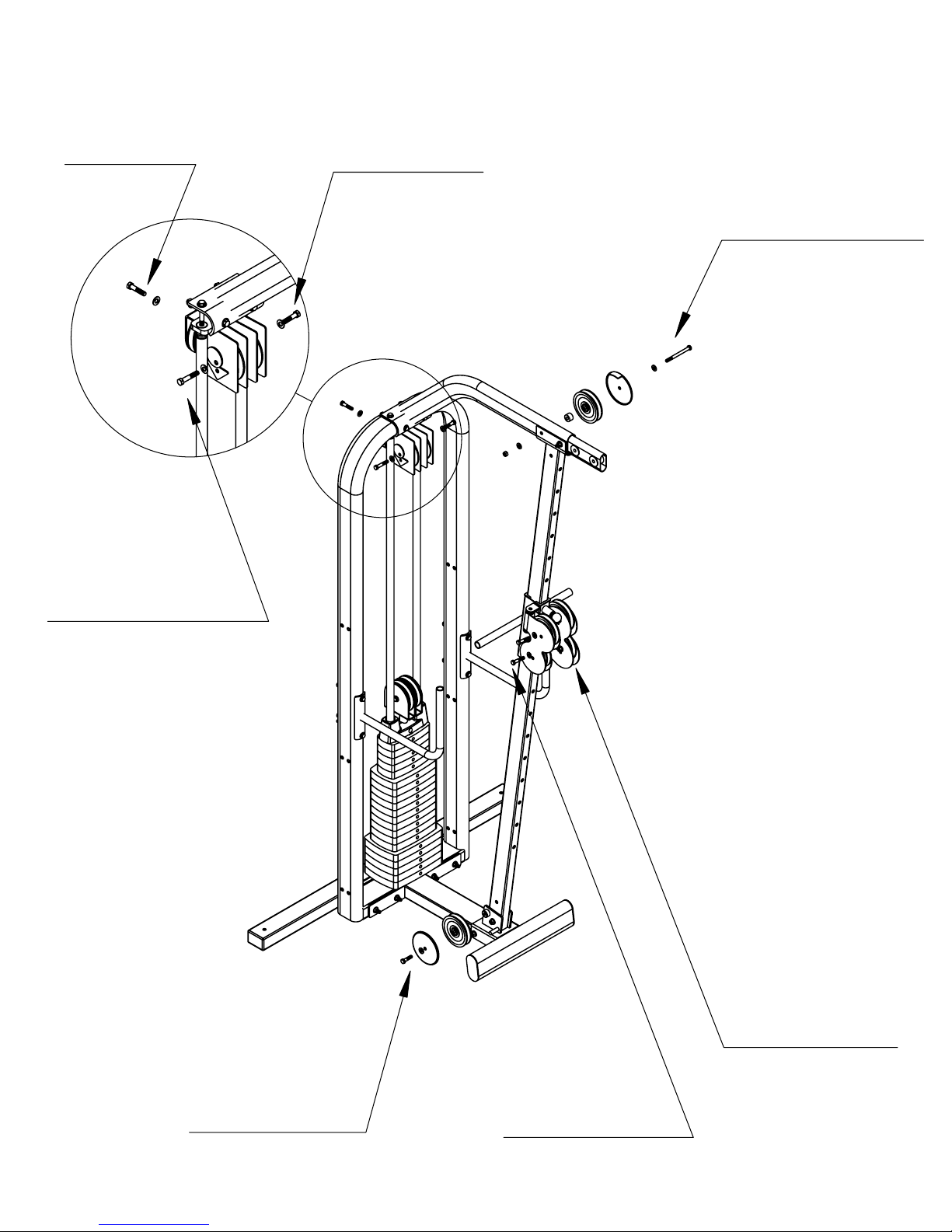
WEIGHT STACK ASSEMBLY AND FRAME COMPLETION
J. Now install the weights only to the assembly that was placed in its final
position. The weights will be installed to the other assembly at Step M.
Insert Guide Rods into the base of the Loop Upright. Allow Guide Rods to
lean back towards stabilizer.
Place one weight stack cushion on each Guide Rod and slide down to the
base. Apply lubricant to the Guide Rods from the weight stack cushions to
the tops of the Guide Rods.
Making sure that the recess for the weight labels is facing towards the chrome
Slider Tube and that the three pads are facing down slide onto the Guide
Rods: 5 – 15lb. Weights, 10 – 10lb. Weights and 5 – 5lb. Weights.
Place Top Weight Assembly on the Guide Rods with the socket head cap
screw facing the chrome Slider Tube and slide down to the stack.
The majority of the cable should now be facing the chrome Slider Tube. The
middle of the cable is at the back of the weight stack.
Install Upper Pulley Bracket by placing the pins into the tops of the Guide
Rods. Stand weight stack up right and fasten Upper Pulley Bracket to the
Loop Upright and Top Beam using the 2 – 3/8” x 2 ¾” bolts and 2 – 3/8” flat
washers installed at Step I.
K. Install the Center Beam Ass’y (from Step A. and E.) into the Top Beam of the
assembly with the weight stack. Remove the 2 ½” bolt and re-install with 2 –
washers and 1 – nut. Remove the 4 ¼” bolt and save for Step T.
CAUTION: Do not pull down on the other end of the Center Beam
- Tipping Danger
L. Align the other assembly with the Center Beam Ass’y. Support the Center
Beam Ass’y. Carefully lift and maneuver the assembly onto the Center Beam.
Remove the two bolts installed through the chrome “U”-bracket as you go.
Re-install the 2 ½” bolt with 2 – washers and 1 - nut. Save the 4 ¼” bolt for
Step T.
M. Repeat Step J. with the assembly just attached.
N. Tighten all the bolts in the entire machine.
8
Detail of weight
cushions
Notes for Step L:
Support the Center Beam and
never pull down.
Slightly lift the Frame Ass'y as
you slide it onto the Center Beam.
This is a two person task.
K
Detail of
Upper Pulley
Bracket
1 - Center Beam Ass'y
1 - 2 1/2" Bolt
(remove and re-install)
2 - Washers
1 - Nut
1 - 2 1/2" Bolt
(remove and re-install)
2 - Washers
1 - Nut
L
1 - Upper Pulley Bracket
2 - Guide Rods
2 - Weight Cushions
1 - Top Weight Ass'y
5 - 5lb. Plates
10 - 10lb. Plates
5 - 15lb. Plates
J & M
9

CCO ASSEMBLY INSTRUCTIONS
CABLE AND PULLEY INSTALLATION
O. Uncoil the cables that are pre-assembled to the top weight. At the rear of the
top weight is the middle of the cable. Make sure the cable is sitting in the
grooves of the two pulleys in the top weight bracket. Lift the middle of the
cable up to the Upper Pulley Bracket at the top of the Guide Rods. Place a
pulley beneath the cable and insert the cable and pulley into the rear “U”-
bracket. Attach with 1 – 3/8” x 1 ¾” bolt and 1 – 3/8” washer. Tighten the bolt.
P. Facing the machine pick up the length of the cable on the left side. Place the
cable over 1 – 4 ½” Pulley and fasten pulley inside the left side “U”- Bracket
at the top of the Guide Rods using 1 – 3/8 x 2” bolt, 1 – Cam Washer 2 - 3/8”
flat washers, and 1 – 3/8” nut. Do not fully tighten now. When the machine is
complete rotate the Cam Washer against the triangular stop to adjust the
tension on the cables and then tighten.
Q. Route this cable end down to the Bottom Bracket. Place 1 - 4 ½” Pulley over
the cable and bolt the pulley to the Bottom Bracket using 1 – 3/8” x 1 ½” bolt
and 1 – 3/8” nut and 1 – Round Cable Retainer. Locate the tab of the Cable
Retainer at the 8 o’clock position. There is a post for a cable retainer welded
at approximately 5 o’clock. Make sure the cable is within the retainers and in
the pulley groove. Tighten the bolt.
R. Install 1 – 4 ½” Pulley between the left hand plates of the Pulley Carriage at
the upper position of the two holes using 1 – 3/8” x 1 ¾” bolt, 2 – 3/8” washers
and 1 – 3/8” nut. Place the cable end over 1 – 4 ½” Pulley and install
between the plates at the lower position using 1 – 3/8” x 1 ¾” bolt, 2 – 3/8”
washers and 1 – 3/8” nut. Tighten the bolts.
S. Take the other cable end of the cable and place it over 1 – 4 ½” Pulley and
install it in the Upper Pulley Bracket using 1 – 3/8” x 1 ¾” bolt, 2 – 3/8”
washers, and 1 – 3/8” nut. Tighten the bolt.
T. Route the cable to the empty hole of the chrome saddle at the top of the slider
tube. Place the cable over 1 – 4 ½” Pulley and install here using 1 – Round
Cable Retainer, 1 – Spacer, 1 – 4 ¼” bolt, 2 – 3/8” washers, and 1 – 3/8” nut.
The retainer’s tab should be at 12 o’clock. Tighten this bolt and the bolts
installed at Steps D. and F.
U. Install 1 – 4 ½” Pulley between the right hand plates of the Pulley Carriage at
the lower position of the two holes using 1 – 3/8” x 1 ¾” bolt, 2 – 3/8” washers,
and 1 – 3/8” nut. Place the cable end under 1 – 4 ½” Pulley and install
between the plates at the upper position using 1 – 3/8” x 1 ¾” bolt, 2 – 3/8”
washers, and 1 – 3/8” nut. Tighten the bolts.
10
1 - Pulley
1 - Cable Retainer
1 - 1 1/2" Bolt
1 - Washer
Q (x 2)
2 - Pulleys
2 - 1 3/4" Bolts
4 - Washers
2 - Nuts
R (x 2)
1 - Pulley
1 - Cable Retainer
1 - Spacer
1 - 4 1/4" Bolt
2 - Washers
1 - Nut
T (x 2)
2 - Pulleys
2 - 1 3/4" Bolts
4 - Washers
2 - Nuts
U (x 2)
11
1 - Pulley
1 - 1 3/4" Bolt
1 - Washer
O (x 2)
1 - Pulley
1 - 2" Bolt
1 - Cam Washer
2 - Washers
1 - Nut
P (x 2)
1 - Pulley
1 - 1 3/4" Bolt
2 - Washers
1 - Nut
S (x 2)
NOTE:
Rest of machine omitted
for clarity

CCO ASSEMBLY INSTRUCTIONS
BALLET HANDLES
V. Attach two ballet handles to each Loop Upright using 8 – 4 ¾” bolts, 16 –
washers, 8 – nuts.
SHROUD HOLES AND SHROUD OPTION
W. If no Optional Shroud Kit was purchased install plastic caps in all 24 shroud
holes. If installing Shrouds fasten to Loop Upright using 12 – 3/8 x 2 ½” bolts,
20 – 3/8” flat washers and 8 – 3/8” nuts (hardware found in Shroud box). The
lower two bolts on each side of the Front Shroud fasten into threaded
fasteners pre-installed into the Front Shroud.
ACCESSORIES AND LABELS
X. Attach Weight Labels in recess provided on front of Weight Plates. All the
recesses should be aligned and to the right as you face the weight stack.
Y. Attach the exercise handles to the cable ends using the quick links.
Notes:
At this time check that all the bolts are tight.
At the end of each rear stabilizer there is an
access hole. Use the hex key supplied to adjust
the rubber feet to stabilize the cable cross.
Pin each weight starting from the top plate down
and lift each plate by pulling the exercise
handle(s). This will set the weights in line for
easier pinning.
12

Cable View: Steps
S, T, U
Handle and Optional Shroud Installation
13
Cable View: Step
O
Cable View: Steps
P, Q, R
Table of contents
Popular Elliptical Trainer manuals by other brands


Xterra
Xterra FSX3500 owner's manual

Thane Fitness
Thane Fitness Orbitrek Elite BK2080 owner's manual

NordicTrack
NordicTrack E10 Rear Drive Elliptical Bedienungsanleitung

Vision Fitness
Vision Fitness X6000 Assembly guide

Sears
Sears Fitness gear 821E user guide

Vision Fitness
Vision Fitness X6600HR Assembly guide