Infloria GS010999 User manual

Walk-in Greenhouse
Article No: GS010999
Assembly Instructions
—— For Single Sliding Door

2
Thank you for purchasing your new greenhouse. We recommend you familiarize yourself
with the instructions and read all safety information before you commence assembly.
These instructions are divided into sections: Base, Part lists, Preparation, Side wall, Rear
wall, Front wall, Roof, Vent, Door, PVC capping bar, Polycarbonate or Glass, Down pipes,
Optional Turbine Vent, Anchoring greenhouse to slab or base etc.
Shelving and Staging inside greenhouse are optional also, not including in this instructions.
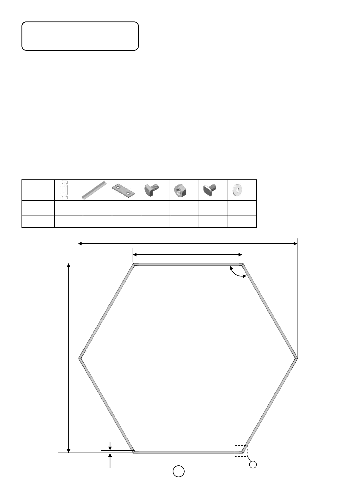
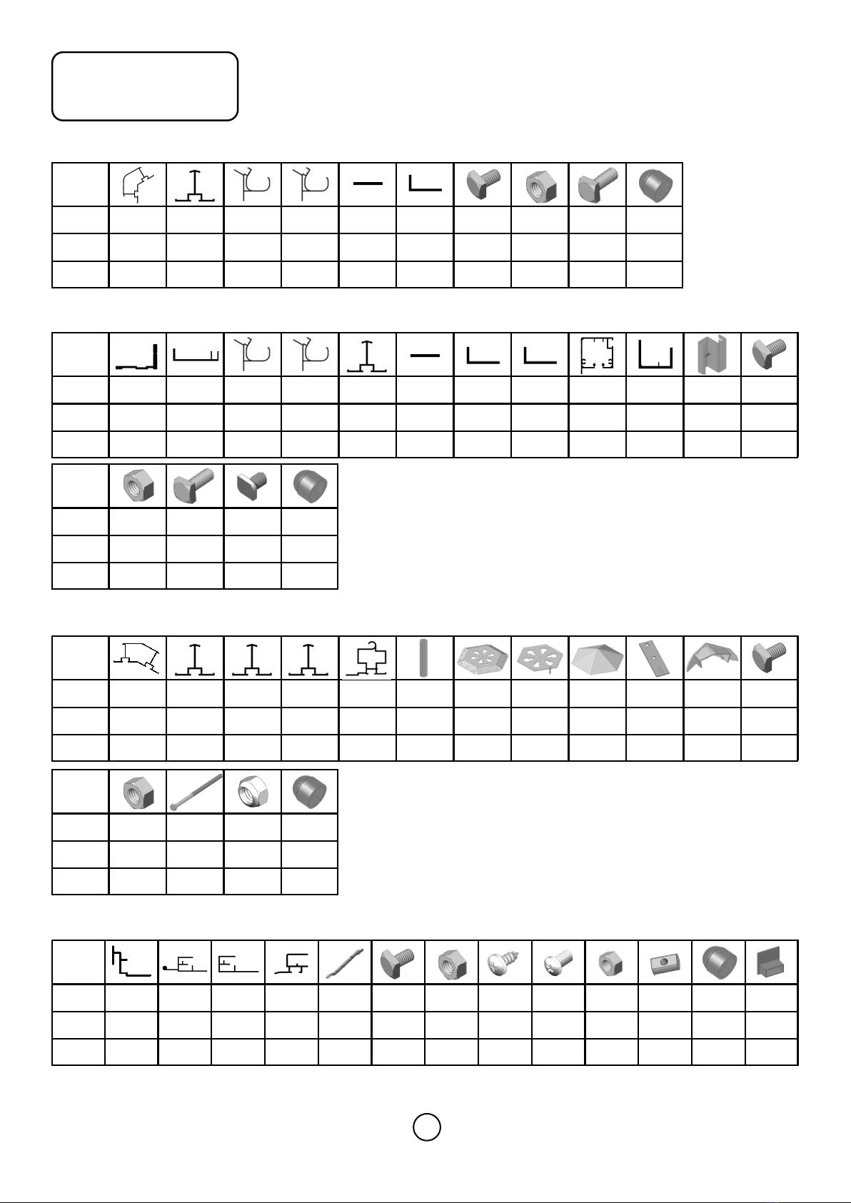
Package1(x2) mainly for side wall parts, Package 2 for front and rear gable parts and side
wall sill bottom bars parts, Package 3 for roof frames and parts, Package 4 for vent parts,
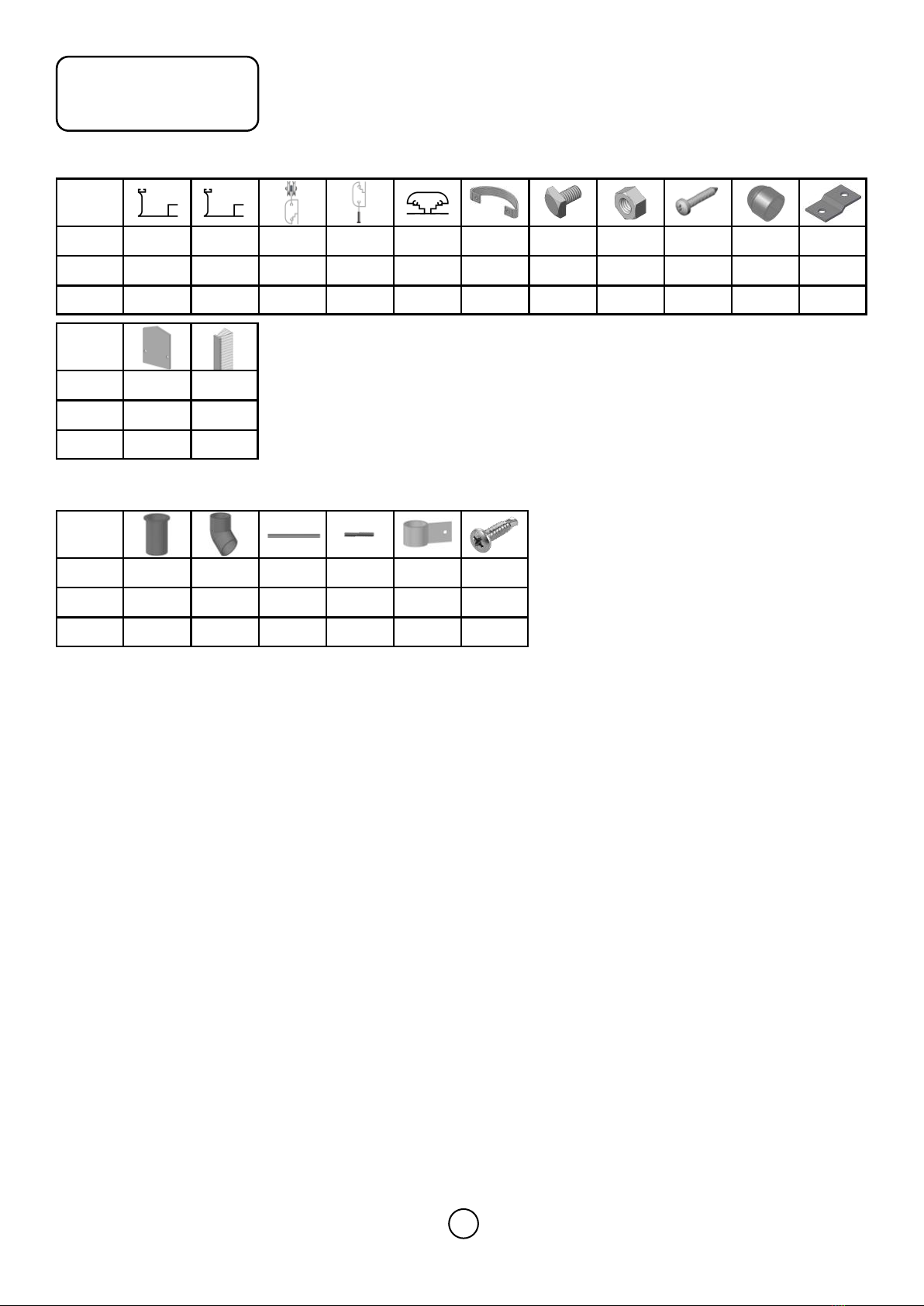
Package 5 for door parts, Package 6 for PVC bars and fixing clips parts, Package 7 for down
pipes parts, and etc.
Safety Warning
1. Aluminum profiles, polycarbonate and glass can potentially cause injury. Please ensure you wear pro-
tective goggles, gloves, headgear and suitable footwear when assembling and glazing the building.
2. Please remember that glass is fragile and should be handled with extreme care. Always clear up and
dispose of any breakages immediately.
3. Do not assemble the greenhouse in high winds.
4. For safety reasons and ease of assembly, we recommend that this greenhouse is assembled by a
minimum of two people.
5. The product you have purchased is intended only for the growing of plants and should only be used
for this purpose. When used for other purposes we will take no responsibility.
6. When using a step ladder one person should steady it at all times whilst the other works.
7. Should you encounter difficulties constructing this house, or in positioning the glass or polycarbonate
sheets, please contact your retailer–do not use force!
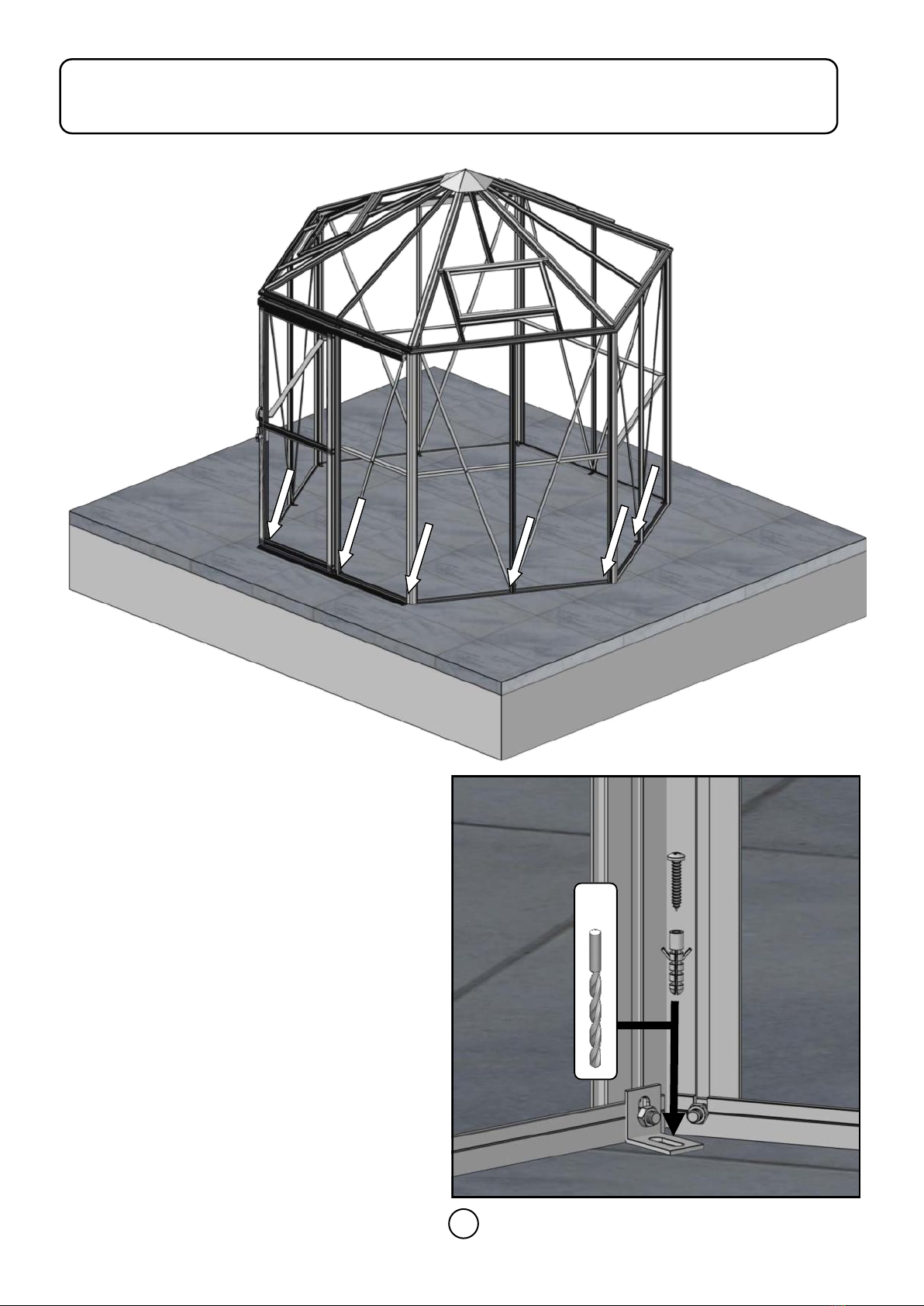
8. The greenhouse must always be anchored.
9. Please clear all lying snow from the greenhouse roof as it can cause the roof to buckle or collapse.
Site Preparation
1. When selecting a site for your greenhouse, Always try to select a sunny location, it is vital that you
choose as flat and level an area as possible.
2. Supplier's original chamber box section Alu. base or a concrete or slab base will provide the most
solid foundation for your greenhouse.
3. Do not fix your building down until the building is fully assembled, including glazing.
4. Avoid placing your greenhouse under trees or in other vulnerable locations.
5. To minimize the risk of wind damage, try to select as sheltered a site as possible, e.g. beside a
hedgerow or garden fence.

3
Important
Before assembling your new greenhouse, please check that all parts in the provided list are included.
Please take each bundle out of the packaging in order to identify the parts better. Most parts are num-
bered and can be identified by a stamped number or removable label. Alternatively, the components can
be identified by lengths detailed in the packing list (see diagram below). Please also note that NOT all
parts for a specific area will be packed together, i.e. door related components are packed together and
some are used in main frame construction. and some side wall bottom sill bars parts were packed in front
& rear wall parts package No.2.
It is important that the opened bundles do not get mixed with one another. If something is missing please
contact your retailer.
Additional Considerations
1. Please bear in mind that assembling your greenhouse can be time consuming. You may need to
spread the construction over two or more days. We recommend that you avoid leaving the building
partially glazed. If you ever have to leave your greenhouse half assembled and not anchored down,
weigh it down with slabs or bags of sand to stop the wind moving it.
2. You will find it helpful to prepare a large, clean and clear area in which to work in. A garage floor or
flat lawn area is ideal.
3. Anchoring down your greenhouse should be the final stage of construction just after glazing.
Necessary Tools
Screw drivers (Normal and Crosshead PH2),10 mm socket spanner or wrench, 10 mm combination span-
ner, knife, measuring stick, spirit level,Accu-drill with adjustable torque, Step ladder.
Maintenance
The greenhouse should be thoroughly washed with a gentle detergent occasionally. Please check that the
detergent used does not react aggressively with aluminium or plastic.
Ensure that the door tracks are cleaned regularly to avoid a buildup of debris , If hinged door, the hinge
should be lubricated usually.
Guarantee
Your new greenhouse is guaranteed for 10 years against faulty manufacture of the framework. This does
not include glazing, moving parts, accidental damage or wind damage etc..

4
Base-Optional
Base Anchor
legs Fixing
tabs M6x10 M6 M6x10
Crop Washer
GS010998 6x1501 6624 30 612
120°
3002
1501
2600
30 1
We cannot emphasis how important it is to have a proper base for your Greenhouse to be erected upon.
It is essential that the BASE IS FLAT, LEVEL AND SUBSTANTIAL enough to take the weight of the
greenhouse including its polycarbonate panels or heavy glass.
Give yourself enough room around your base to allow for fitting the polycarbonate panel or glass and any
ongoing maintenance / cleaning. A slab base which is larger than the greenhouse is the ideal solution and
is our preferred foundation. If you use supplier's original chamber box section alu. base, also recom-
mended.
A brick perimeter base is equally suitable providing there is a concrete foundation beneath it. We suggest
using a solid brick with no frogs or holes (quality stock bricks or semi-engineering bricks).
IMPORTANT: Do not anchor your greenhouse down until it is fully assembled including glazing unless you
are 100% sure your base is square and level. If not your polycarbonate panels or glass will not fit properly.
Article No: GS010998

5
1
Base
IMPORTANT Before assembling aluminium base, the end trough centers of seven legs should match
both end trough centers of side sills and front & rear sills at the same time.
Please match six legs
troughs together at the
same time
side sills
side sills

6
1. For this final stage you will need No.10 X
2” screws, grey wall plugs, a 8mm ma-
sonry drill bit and a hammer drill.
2. Fixing the greenhouse to the ground is
very simple to do. When you built the
front, rear and side assemblies you will
have attached base brackets (m5) in spe-
cific places around the building.
3. Make sure the greenhouse structure is
square (Diagonal measurements should
be equal) and level.
4. Drill down through the holes in the base
brackets into the concrete.
5. Insert a wall plug into each hole.
6. Finally drive a screw into each hole.
7. You can now check the greenhouse and
look for any gaps where water might
come in, fill these using the silicone sup-
plied.
8. Your greenhouse is now complete.
Anchoring building to slab / concrete base
8mm

7
Parts List
# 7901 7607 7905 7906 7910 7911 a1 a2 a3 a20
Size 1922 1922 1520 1520 2033 1450 M6x10 M6 M6x15 -
QTY 32114220 26 626
Package 1
# 7022 7930 7904 7906 7607 7910 7911 7944 7121 7120 7166 a1
Size 1462 1462 1520 1520 1922 2033 1450 733 1435 739 102 M6x10
QTY 5111231111121
Package 2
# a2 a3 a20a9
Size M6 M6x15 -M6x10
QTY 29 6292
# 7914 7916 7917 7918 7921 7991 7992 7993 7994 m3 p10 a1
Size 1534 1352 695 623 819 81 -----M6x10
QTY 6336311119663
Package 3
# a2 a24 a25 a20
Size M6 M6x110 M6-L -
QTY 63 1163
# 7950 7951 7952 7924 7953 a1 a2 a4 a7 a10 p3 a20 p11
Size 631 610 593 400 250 M6x10 M6
Φ3.9x8
M4x8 M4 ---
QTY 1112166222264
Package 4

8
Parts List
# 7938 7939 7061 7062 7063 7065 a1 a2 a5 a20 m13
Size 1838 1838 715 715 715 -M6x10 M6
Φ3.5x19
-
-
QTY 1111114416 41
# G-p5 FLUFF
Size -1838
QTY 22
Package 5
# P11 P12 P13 P14 P15 a18
Size 1400 200 Φ3.5x13
QTY 222222
Package 7

9
BASE
Base dimensions and recommendations. Ensure that your base is level as this will make assembly of
the building, especially the glazing of the roof much more straight forward.
PARTS LIST Most components should have a code punched into their metal surface. Identify and
separate all like for like components prior to assembly. The parts lists also separates parts into the various
sections Package1 - Package 7 shown above. Parts can also be identified by their profile pictures and
stated lengths etc..
PREPARATION The frame is assembled by feeding square headed bolts, either 10mm or 15mm in
length into the slots on glazing bars and then locating those bolts through holes in purlings and cills, etc…
Twist in (rectangular) crop headed bolts are also used towards the end of construction to attach compo-
nents to the frame when the glazing bar slots are no longer exposed at the ends.
SIDE WALL
Use 10mm and 15mm bolts to join the components (note how the head of the bolt slides into each glazing
bar during construction). The correct choice of bolt is highlighted with a number #a1/#a3 in each of the dia-
grams.
Do the same for Rear wall & Front wall later.
JOINING TWO SIDE WALL SECTIONS TOGETHER 1
------REAR WALL
Use the gutter #7906 and sill #7022 and side horizontal bracing bar # 7911 to join two side wall together
on rear wall. It is a good idea to tie some step ladders to the sides to support them if you do not have any-
one to hold them for you.
JOINING TWO SIDE WALL SECTIONS TOGETHER 2
------ FRONT WALL
Use the gutter #7904 and sill #7930 to joining two side wall together on front wall.
IMPORTANT: Door post #7607 should connect gutter #7904 and sill #7930 in center hole, the other two
holes beside of #7904 were used for hinged door only, this is sliding door greenhouse, so use central hole
of gutter #7904 only.
The door lock strike height could be adjusted based on door lock position later.
The door track support #7120 height will be exactly below the gutter #7904.
ROOF
Assemble 6 roof corner bars #7914 on hexagonal roof bracket #7992. Please note #7914 overlap bracket
by distance of 42 mm. Tighten all bolts.
Then lift the assembly onto the roof, Herein you should use step ladders. Loosely connect the roof corner
bars to the eaves at all 6 corners.
Please note: At this stage you need to decide where your roof vents are positioned so that you could insert
an extra bolt into each roof corner bar either side of a vent opening.
Connect 3 roof vent hinge beam #7921 to roof corner bar with joining plate #m3.
Join 3 short roof glazing bars #7917 between the hexagonal roof bracket #7992 and the center of vent
hinge beam #7921. Please note: #7917 overlap bracket by distance of 24 mm at the one end, and con-
nected vent hinge beam by joining plate #m3 at the another end.
Join 3 roof glazing bars #7916 between the hexagonal roof bracket #7992 and the center of eave. Please
note #7916 overlap bracket by distance of 24 mm, tighten all bolts.

10
Assemble the outer hexagonal ridge cone #7994 over the assembled profiles on hexagonal bracket, using
long bolt #a24, spacer #7991, open-close disc #7993 and locknut #a25.
DOOR ATTACHMENT
The door lock strike height could be adjusted based on door lock position later.
The door track support #7120 height will be exactly below the gutter #7904. It could be adjusted also. t
Bracket #m13 was used to support door track #7121. It’s used to connect door track #7121 and gutter
#7904, you should drill a hole on gutter #7904 by using a drill of diameter of 7mm.
GLAZING
For roof glazing, when glazing panels under hexagonal ridge cone (assembled already), PVC capping
could be started to push in from middle upper area, then slid to the top area of panels.
Also for #XH & #XG panels above vent, We should push pre-cut 388mm length PVC capping bars in
place firstly, the PVC tilted & trimmed end touch the edge of roof corner bar. Let them no gap to
avoid water leaking. and then push another two 695mm and 777mm length PVC capping bars on both
sides, slid from middle upper area to top area also.
For glass glazing, on the side walls, the single sided adhesive foam goes longitudinally over the green-
house frame, the glass just sits directly onto the aluminium cills. Two glass fixing clip holding the glass on
top in order not to let glass fall down. Remove the white paper on the foam before it gets wet as it is diffi-
cult to remove, i.e. it comes off in small pieces.
Layout the bar capping around the building like a sundial checking that all is present and correct. You
can also place the roof capping in the gutters so they are closer to hand. It is a good idea to glaze two
roof sections first to ensure the building is square followed by two side sections to ensure the building
isn't leaning. Make sure the building is square and level before you undertake the glazing and make sure
that you do not leave the building part glazed to prevent wind damage.
FINISHING TOUCHES
Now that the main body of the structure is complete you can add: downpipe fittings and roof corner bar
end cover #p10. Use the silicone to seal between the gutter sections. The downpipe bracket #p15 are at-
tached by carefully using #a18 self-drilling tapping screws which will bore into aluminium or plastic. The
water outlet jointer #p11 edge should be trimmed firstly to match the gutter hole better.
ANCHORING DOWN
Now that the greenhouse is finished and the door is operating without interference you need to anchor
the building on base by base fixing tabs or base brackets.

11
# 7901 7607 7022 7905 7906 7910 7911 a1 a2 a3 a20
Size 1922 1922 1462 1519 1519 2033 1450 M6x10 M6 M6x15 -
QTY 322114220 26 626
Package 1
Package 2
Side wall In Package 1 & Package 2
1
7901
7901
7901
79057906
7607 7607
7022 7022
7910
7910 7910
7910
7911 7911
2
3
4
567
8
9
10
12
11
123
7901
7022
a3/a2 a3/a2 a3/a2
7022
7910 7910
7607 7901
7022 7022

12
Side wall
456
78
9
10
11
12
7901
7911
7911
7910
7911
7607
7911
7910
7911 7911
7901
7901 7910
7906 7906
7607
7906 7905
7901
7910 7910
7906 7905

13
Rear wall
# 7022 7906 7607 7910 7911 a1 a2 a3 a20
Size 1462 1519 1922 2033 1450 M6x10 M6 M6x15 -
QTY 1112110 13 313
In Package 2
—— Join Side wall together
1
2
7906
7022
2
1
a3/a2
7022
7906
a1/a2

14
Rear wall
34
567
8
7022
7906
7607
7910 7910
7911
345
678
7906
7910
7901
7906
7607
7901
7911 7911
7911
7910
7911
7607
7022
7910 7910
7607
a3/a2

15
# 7904 7930 7607 7910 7944 7121 7120 7166 a1 a2 a3 a20a9
Size 1519 1462 1922 2033 733 1435 739 102 M6x10 M6 M6x15 -M6x10
QTY 1111111111 16 3162
Front wall In Package 2
—— Join Side wall together
7904
7930
1
2
1
2
7904
a1/a2
7930
a3/a2
7904
45
6
7
89
10
11
76077910
7944
71207121
7930

16
Section View
7120
7121
a1/a2
Front wall
3
456
789
11
10
7121
7120
7120
7904
7120
7904
7607
7166
7901
7910
7904
7944
7901
7944
7910
7944
7607 7607
7910
7930
a9/a2

17
Roof
# 7914 7916 7917 7918 7921 7991 7992 7993 7994 m3 p10
Size 1534 1352 695 623 819 81 -----
QTY 63363111196
# a1 a2 a24 a25 a20
Size M6x10 M6 M6x110 M6-L -
QTY 63 63 1163
7914
7914
7914
7992
12
7914
7992
42mm
7914
1
2
7992
7914
In Package 3
7914
7914 7914

18
Roof
34
56
78
7914 7914
7914 7914
7914 7914
7916 7916
7916
7917
7917
7917
7918
7918
7918
7918
7918 7918
7921
7921 7921
34
5
6
7
8
7992
7916
7992
7916
24mm
7916 7917
7921
m3
7921
7914
7918
m3
7918

19
9
9
a24
a25
7991
7992
7993
7994
Roof
10
10
p10
7914
open close

20
Vent
# 7950 7951 7952 7924 7953 7067 a1 a2 a4 a7 a10 p3 a20 p11
Size 631 610 593 400 250 -M6x10 M6
Φ3.9x8
M4x8 M4 ---
QTY 11121266222264
1
23
7950
7918 7918
23
7918
7950
7950
7067
a7
a10
1
7951
7924
7924
4
4
7951 7924
In Package 4
Table of contents
Other Infloria Greenhouse Kit manuals
Popular Greenhouse Kit manuals by other brands

Robinsons
Robinsons Rosette DWARF Assembly instructions

GrowSpan
GrowSpan PB01750R6 Assembly instructions

Juliana
Juliana Premium Wall Assembly instructions

Kogan
Kogan CERTA CTGAGH211SA user guide

Dancover
Dancover GH152200 Assembly instructions

Poly-Tex
Poly-Tex FieldPro Gothic High Tunnel 30 installation instructions