Louvre
1
Montagehandleiding / Instructions de montage /
Montageanleitung / Manual
6 L, 610 W x 610 H mm, blank RW0254
6 L, 610 W x 610 H mm, groen gecoat RW2591
6 L, 610 W x 610 H mm, zwart gecoat RW2592
Louver Assembly Instruction
— 526x592 mm
For the louver assembly you will need 1 top sill, 1 bottom sill, 2 side jambs (one with han-
dle), 4 self-tapping screws, 4 crop head bolts and nuts and glass blades .
Procedure:
1. Installation of Louver frame
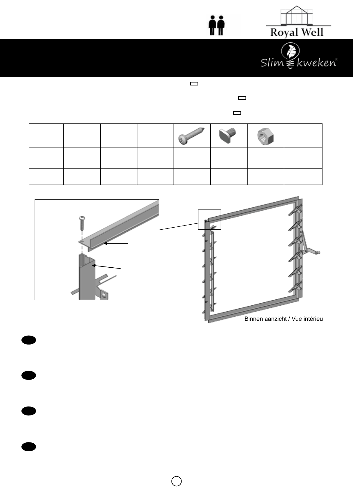
*Place the top sill into position on side jamb of louver and secure with self tapping screws.
*Do the same on the other top corner.
*Do the same with bottom sill.
*Please note that the handle is on the right hand side. The diagrams are viewed from in-
side.
jamb1 jamb2 sill Glass
Size 526 526 592 Φ3.5x19 M6x10
Crop M6 573x100
QTY 1124446
Top sill
Side jamb
2. Installation of louver to the structure
*The louver is fitted after the unit is assembled fully and during glazing.
*The louver is fitted to the vertical glazing bar/wall utilizing either 4 unoccupied bolts previously
inserted, or the 4 crop head bolts supplied with the louver kit.
*The louver is fitted from inside the structure with the angle jams fitting around the vertical
greenhouse bars concerned.
*The louver handle is on the inside of the greenhouse and is fitted to the right of the louver ( as
viewed from the inside)
*First you should locate where to fit the louver. In that case it will be necessary to cut the glass
either above or below the position in which you decide to local the unit.
Binnen aanzicht / Vue intérieure /
Innenansicht / View from inside
Louver Assembly Instruction
— 526x592 mm
For the louver assembly you will need 1 top sill, 1 bottom sill, 2 side jambs (one with han-
dle), 4 self-tapping screws, 4 crop head bolts and nuts and glass blades .
Procedure:
1. Installation of Louver frame
*Place the top sill into position on side jamb of louver and secure with self tapping screws.
*Do the same on the other top corner.
*Do the same with bottom sill.
*Please note that the handle is on the right hand side. The diagrams are viewed from in-
side.
jamb1 jamb2 sill Glass
Size 526 526 592 Φ3.5x19 M6x10
Crop M6 573x100
QTY 1124446
Top sill
Side jamb
2. Installation of louver to the structure
*The louver is fitted after the unit is assembled fully and during glazing.
*The louver is fitted to the vertical glazing bar/wall utilizing either 4 unoccupied bolts previously
inserted, or the 4 crop head bolts supplied with the louver kit.
*The louver is fitted from inside the structure with the angle jams fitting around the vertical
greenhouse bars concerned.
*The louver handle is on the inside of the greenhouse and is fitted to the right of the louver ( as
viewed from the inside)
*First you should locate where to fit the louver. In that case it will be necessary to cut the glass
either above or below the position in which you decide to local the unit.
INSTALLEREN / INSTALLER / INSTALLIEREN / INSTALLATION
• Vanuit de binnenkant bekeken hoort de handgreep aan de rechterkant
• Plaats het proel B in op de zijproelen A1 + A2 en zet ze vast met zelftappende schroeven
• Doe hetzelfde met de onderdorpel
• Plaats het louvre frame tussen 2 ruiten of tussen de grond ligger en een ruit
• Bevestig het louvre frame aan de kasroeden met behulp van hamerkopbouten en moeren
• Vu de l'intérieur, la poignée doit être à droite
• Placez le prolé B sur les prolés latéraux A1 + A2 et xez-le avec des vis autotaraudeuses
• Faites de même avec le seuil
• Placez le cadre de la grille entre 2 fenêtres ou entre le sol et une fenêtre
• Fixez le cadre de la grille aux barres de la serre à l’aide de vis à tête marteau et d’écrous
• Von innen gesehen sollte sich der Gri rechts benden
• Prol B auf die Seitenprole A1 + A2 legen und mit Blechschrauben befestigen
• Machen Sie dasselbe mit der Schwelle
• Platzieren Sie den Lamellenrahmen zwischen 2 Fenstern oder zwischen dem Bodenträger und einem Fenster
• Befestigen Sie den Lamellenrahmen mit Hammerkopfschrauben und Muttern an den Gewächshausstangen
• Viewed from the inside, the handle should be on the right
• Place prole B on side proles A1 + A2 and secure with self-tapping screws
• Do the same with the sill
• Place the louvre frame between 2 glass panes or between the ground girder and a glass pane
• Attach the louvre frame to the greenhouse bars using hammer-head bolts and nuts
NL
F
D
GB
A1 A2 B
A1
B
A1
A2
B
B
Hamerkop
Size
in mm 567 567


