Influx Technology K-Box Operator's manual

User Documentation
K-Box
Influx Technology
WWW.INFLUXTECHNOLOGY.COM Ver 2.7
30/10/2017

1.0 Introduction............................................................................................................................................................................. 3
2.0 Connecting and powering the K-Box ....................................................................................................................................... 4
2.1 Enable the AUX Power setting within the Logger Configuration ........................................................................................ 6
3.0 Configuring the K-Box.............................................................................................................................................................. 9
3.1 Installing the Kvaser Drivers:............................................................................................................................................... 9
3.2 Installing the Rebel Drivers................................................................................................................................................ 13
3.3 Installing the K-Box Cal Software: ..................................................................................................................................... 15
3.4 Using the K-BoxCal Software ............................................................................................................................................. 17
3.4.1 Configuring the Analog Channels ............................................................................................................................... 18
3.4.2 Configuring the Digital Channels ................................................................................................................................ 19
3.3.2.1 The Input Function .............................................................................................................................................. 20
3.3.2.2 Pulse Duration Measurement ............................................................................................................................. 20
3.3.2.3 Frequency Measurement .................................................................................................................................... 21
3.3.2.4 Cycle Duration Measurement ............................................................................................................................. 22
3.3.2.5 Duty Cycle/PWM Measurement ......................................................................................................................... 22
3.3.2.6 Event Measurement............................................................................................................................................ 24
3.3.2.7 RPM Measurement ............................................................................................................................................. 25
3.3.2.8 The Output Function ........................................................................................................................................... 26
3.4.3 Reprogramming the K-Box ......................................................................................................................................... 29
3.4.4 Calibrating the K-Box.................................................................................................................................................. 31
3.4.5 Erasing the Calibration ............................................................................................................................................... 35
4.0 Using K-Box Cal to display data. ............................................................................................................................................ 36
4.1 Channel Display and Conversion ........................................................................................................................................... 37
4.1.1 Selecting the Channel to display ................................................................................................................................ 37
4.1.2 Creating a Conversion Table....................................................................................................................................... 38
4.1.3 Applying a Conversion Table to a Channel. ................................................................................................................ 39
4.1.4 Applying a Formula to a Channel. .............................................................................................................................. 40
4.2 Using the Oscilloscope to display data.................................................................................................................................. 42
4.2.2 Adding items to the Oscilloscope ............................................................................................................................... 43
4.2.2.1 Individually Adding items to the Oscilloscope......................................................................................................... 43
4.2.2.1 Adding All Channels to the Oscilloscope (Method 1) .............................................................................................. 44
4.2.2.2 Adding All Channels to the Oscilloscope (Method 2) .............................................................................................. 45
4.2.2.3 Working with items added to the Oscilloscope....................................................................................................... 46
4.2.3 Using the Oscilloscope................................................................................................................................................ 47
4.2.4 Exporting a DBC file with conversion tables and Formulas ........................................................................................ 49
5.0 Loading the K-Box configuration into DiaLog. ....................................................................................................................... 50
Appendix 1: Specifications .......................................................................................................................................................... 58
Appendix 2: Pinout of the K Box.................................................................................................................................................. 59
Appendix 3: Pinout of the Multi Connect Cable.......................................................................................................................... 62

1.0 Introduction
The K-Box is Influx’s stackable instrumentation which is compatible with the Rebel range of data loggers but will also
integrate with any device that can be configured via DBC files, even other logger systems or used to output signals on CAN to
the Rebel Dash display.
The K-Box is an ideal solution for applications that require a large number of thermocouple and analog inputs. The K-Box’s
accurate sensor data is transmitted periodically on the CAN bus which enables multiple devices to be connected. The K-Box
CAN bus settings, calibration and sampling rates are all easily configurable, and these settings are stored within the K-Box
even when the device is not powered.
Advantages:
•Wide switchable software voltage input ranges +/-80V,+/-40V,+/-20V or +/-10V
•Accuracy Analog ±0.0015%, Thermocouples ±0.08%.
•High input impedance
•Isolated Differential Inputs to prevent earthing problems
Key features:
•Stackable enclosure
•Simple signal configuration using a DBC file
•Each unit enables up to 8 K-type connections at 20Hz sampling rate and 8 Analog inputs at 1kHz sampling rate
•Pulse Width Measurement: 3 inputs frequency measurements or pulse measurements.
•Regulated +5V and +12V output power supply for external sensors
•Instrumentation data time synchronised with the recorded vehicle network data
•Analog inputs and thermocouple inputs are galvanically isolated
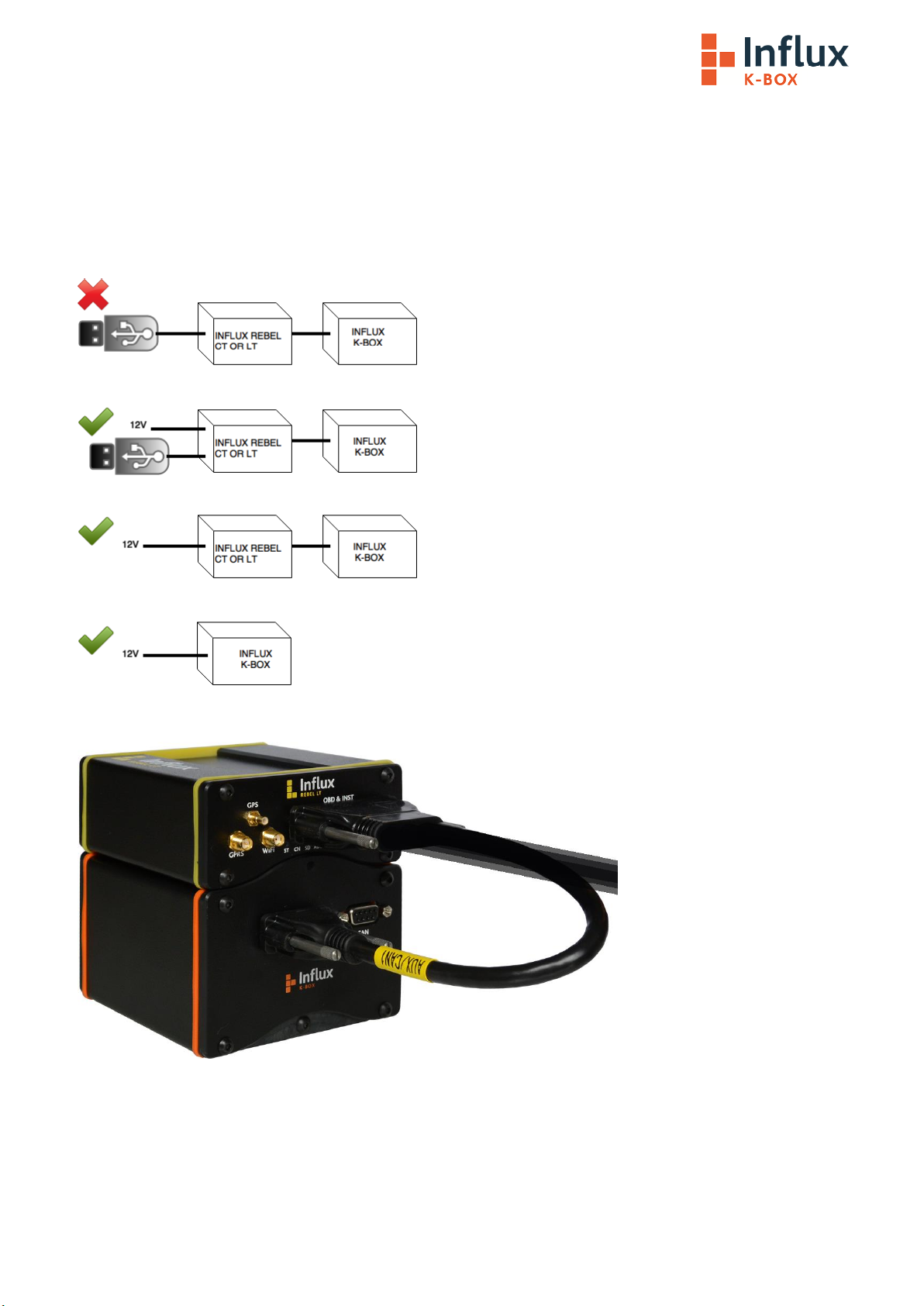
2.0 Connecting and powering the K-Box
The K-Box is powered via the CAN and power connectors and has been designed with CiA® 102 pinout for the CAN bus and
power in order to make connecting the device as simple as possible.
Most commonly it will be powered from a Rebel Logger using the Multi Connect Cable but you can also power it via pin 9 (4.5
to 36V) and pin 5 PowerGND of the 9 pin Sub D connectors. If connected via the Multi connect cable the CAN 1 (MS) bus is
also connected to allow the Logger to record the data transmitted from the K-Box.

The pinout of the required Cable between the two K-Boxes is as follows:
•Several K-Boxes can be daisy chained via the additional DB9 Connector, however, they must
have power supplied seperatly via power breakout in the cable, not via the Logger, it can
also be used to connect other devices such as the Rebel Dash.
Warning
2.1 Enable the AUX Power setting within the Logger Configuration
If you power it from the Logger, the Logger will need to be powered from the vehicle or an external power source
(NOT just via USB) and you will need to make sure the AUX power feature in the configuration is set to on. To do this follow
the Steps Below:
Step 1
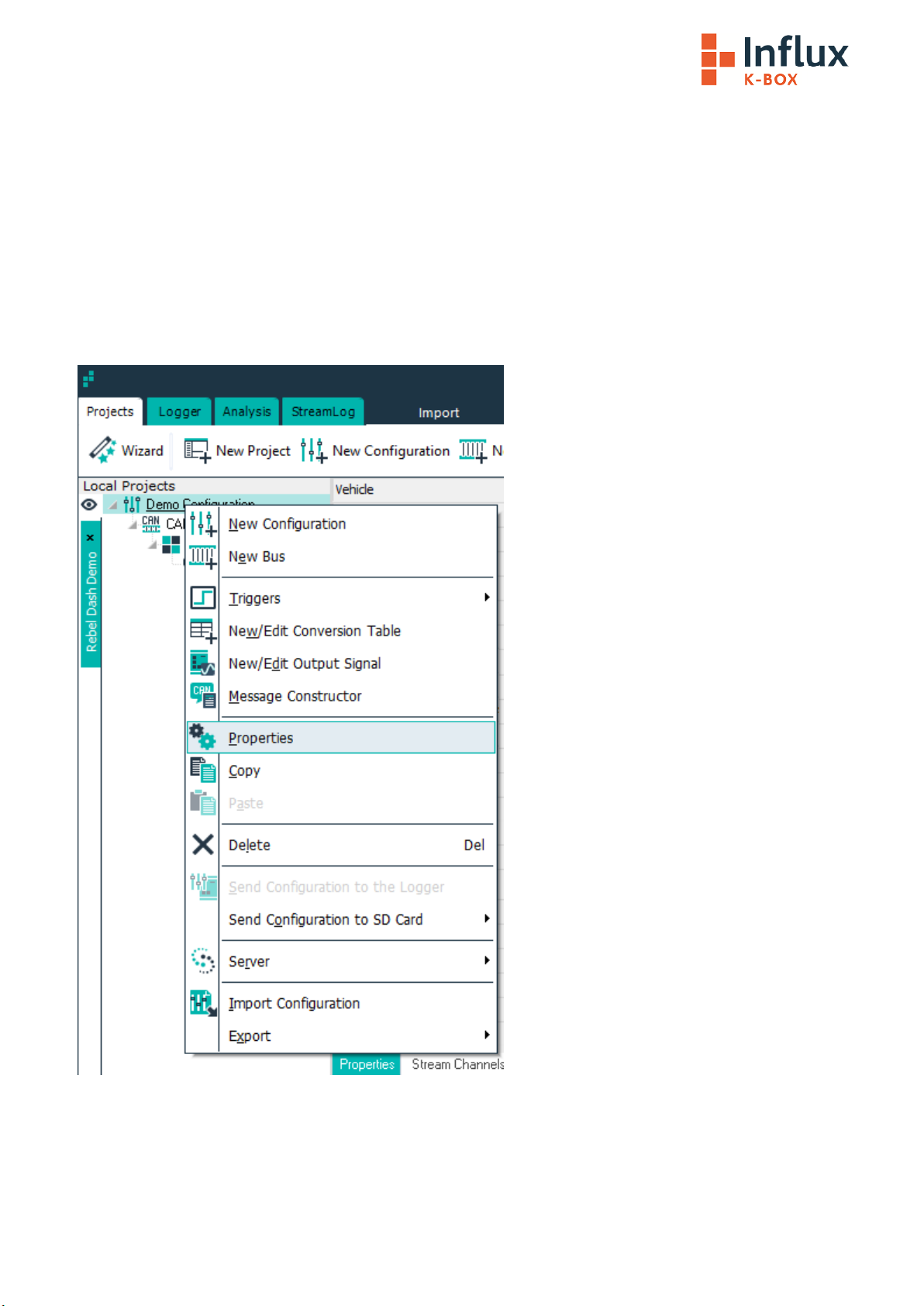
Right click on the Project that you want to configure and select ‘Properties’, If you need to create a configuration this is
detailed in the ‘Loading the K-Box configuration into DiaLog’ section in this document.

Step 2
Once the Edit Configuration window is displayed, Click on the ‘Settings’ Tab and put a Check mark in Aux Power On.
Step 3
Click OK to set the Aux Power on Setting in the Configuration…

Step 4
Send the configuration to the Logger by right clicking on the Project and choosing “Send Configuration to the Logger”
If you have the CAN bus that the K-Box is connected to set to the right speed within your project you will see the Status Light
on Solid Orange and the CAN Light on Solid Green, if it is flashing green the CAN bus is misconfigured, check the speed and
termination.
•Within the Project you should have the bus that the K-Box is connected to Setup as CAN 1
(MS) if you are using the AUX connector of the Multi Connect Cable.
Important Note
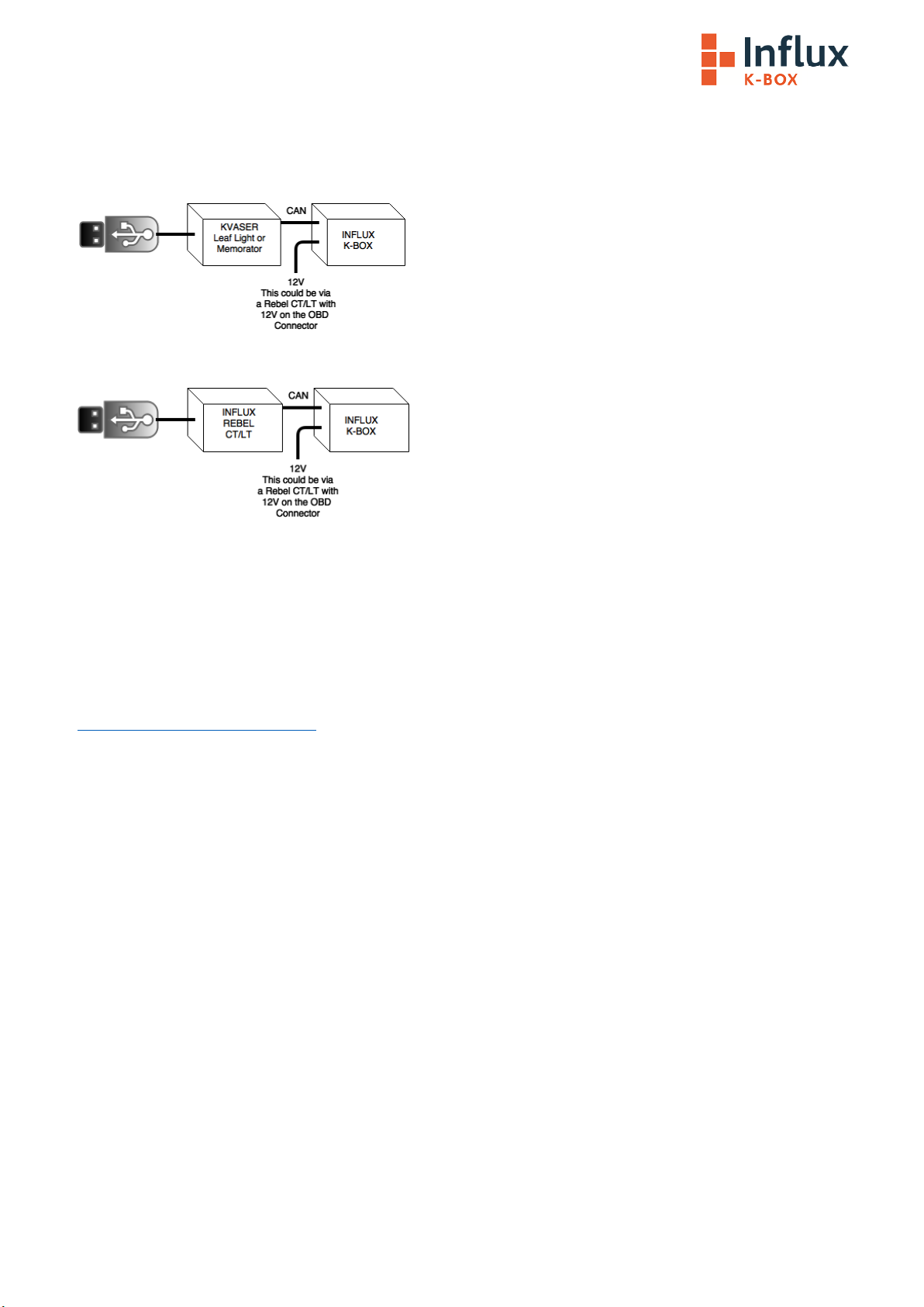
3.0 Configuring the K-Box
The K-Box comes pre configured but the configuration is programmable using the K-Box Calibration utility. It requires a
Kavser Leaf Light, Memorator or an Influx Rebel CT or LT to be installed and the K-Box Calibration utility.
For the above example please install the Kvaser Drivers
For the above example please install the Rebel Drivers
3.1 Installing the Kvaser Drivers:
Step 1
Download the Kavaser Drivers for Windows, they are located at:
https://www.kvaser.com/downloads/
Step 2
Run kvaser_drivers_setup.exe
Step 3
Click Next to start the Installation

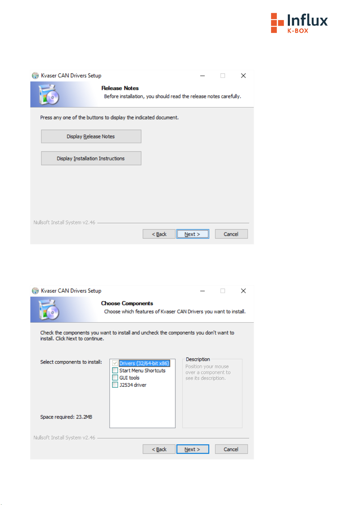
Step 4
Click Next after viewing the documentation (optional)
Step 5
Select the item(s) you wish to install, you will need to install at least the Drivers.
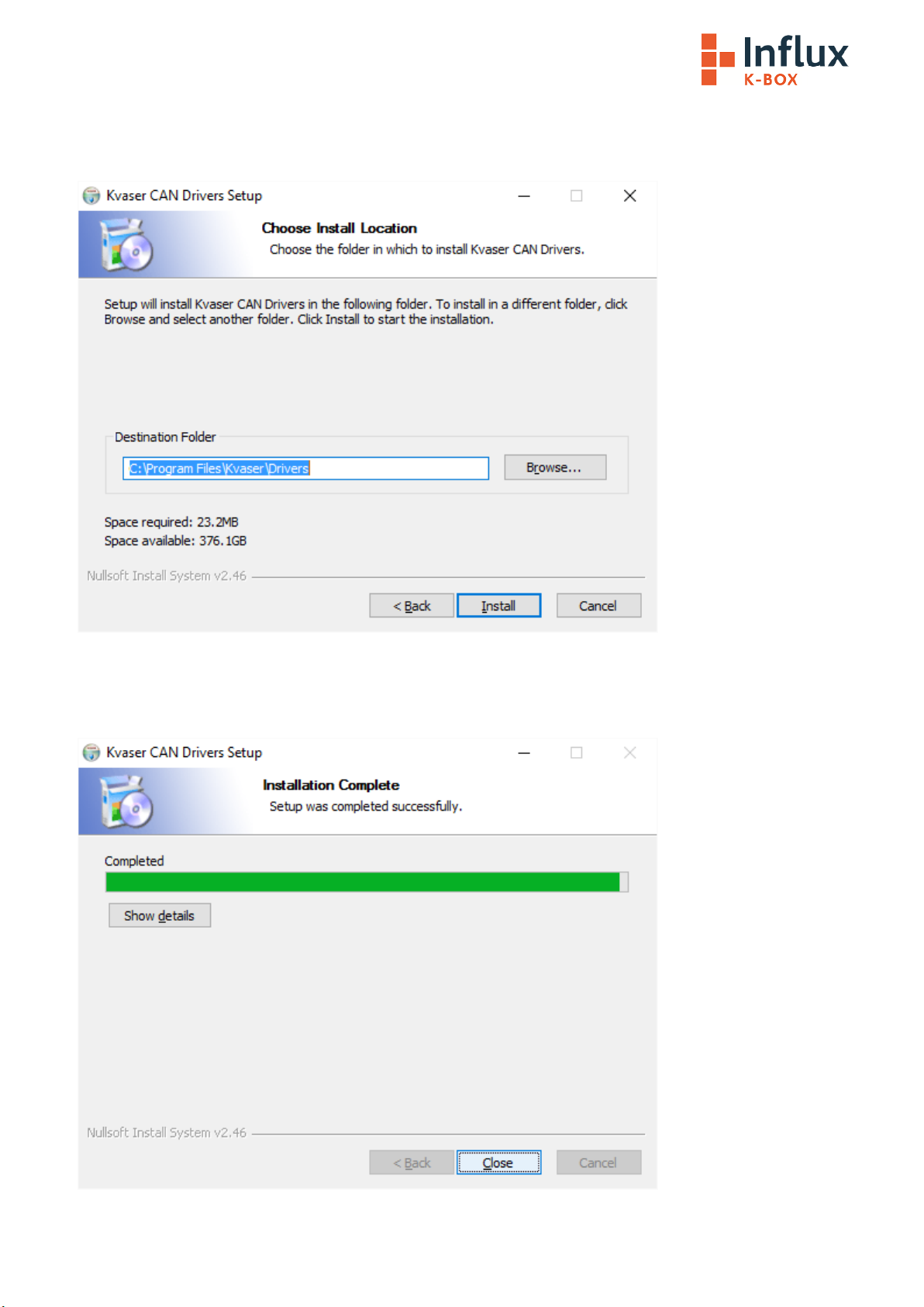
Step 6
Choose or confirm the location that you wish to install the drivers to.
Step 7
The Drivers will be installed, click close once the process is complete.
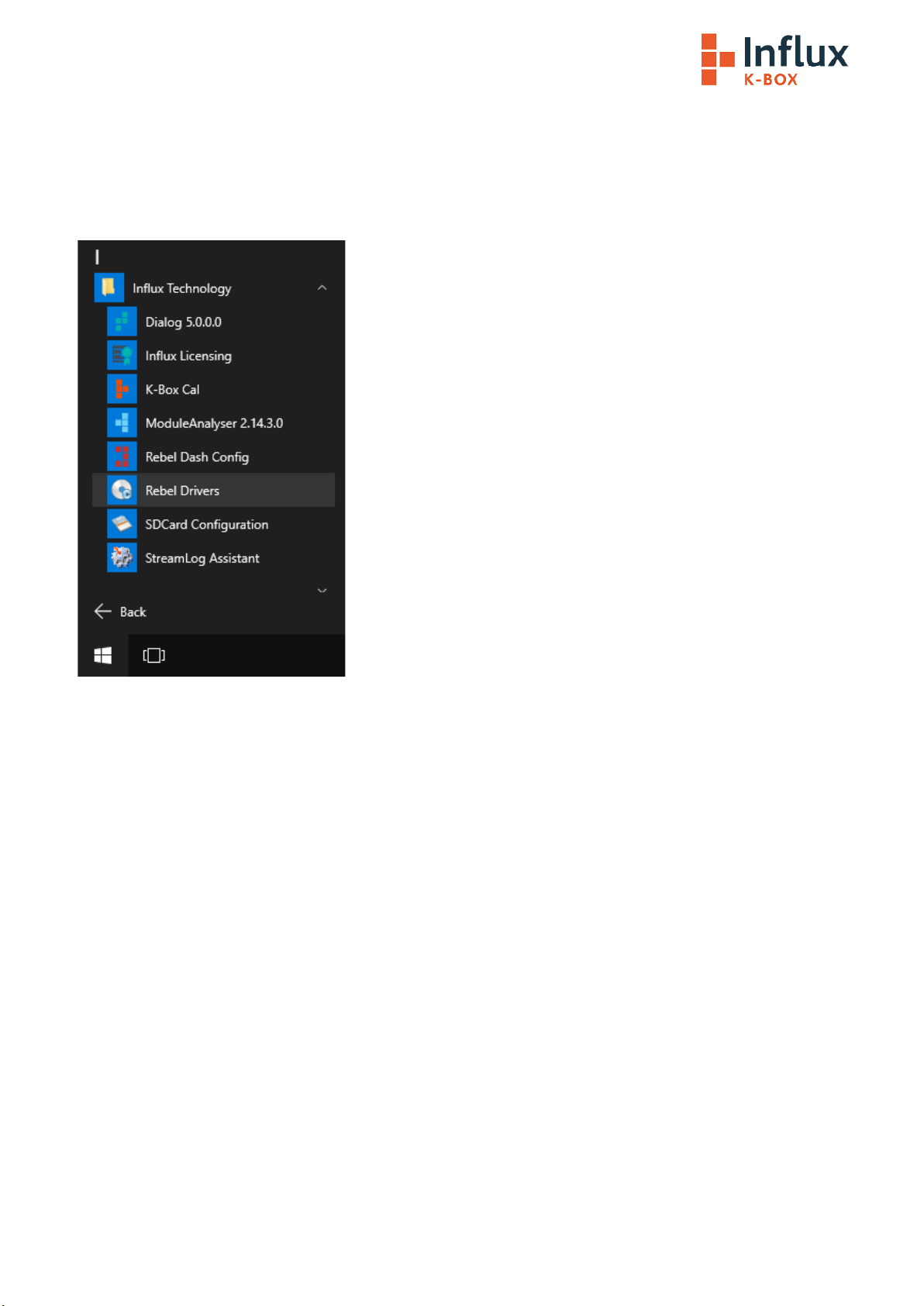
3.2 Installing the Rebel Drivers
The Rebel drivers must be correctly installed to ensure the Rebel functions correctly.
If DiaLog is installed, there will be a driver installation application avaiable, which can be found in the Influx Technology
folder of the Start Menu as shown below.

Ensure the Rebel is not plugged in and click ‘Next’ to continue.
Please read and accept the EULA, then click next to continue.
The driver installation will begin and may take a few moments.
Once the installation is complete, click ‘Finish’ to close the application.
Plug in the Rebel to allow the drivers to be recognised.

3.3 Installing the K-Box Cal Software:
Step 1
Run the K-BoxCal.msi
Step 2
Click Next to start the installation
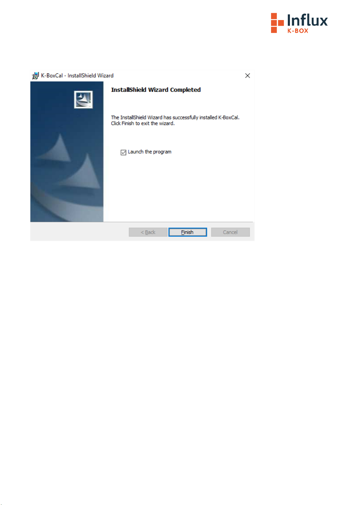
Step 3
After the K-BoxCal software is installed click finish

3.4 Using the K-BoxCal Software
Once you launch the K-Box Configuration utility you will see the settings for the Interface you are using and if the K-Box is on
and connected its serial no and firmware version will be displayed at the bottom of the screen.
Pressing the Load Button Loads the settings contained in the K-Box and displays them on the screen.
On the General Tab you can change the following parameters:
•The Baud rate that the K-Box will communicate on the CAN Bus at.
•The Byte order that the K-Box will use
•How long it takes before the K-Box enters Sleep Mode, if you do not wish to use this feature and want the K-Box to
remain on while power is supplied, simply select No Sleep.
Pressing the Commit Button commits the settings that are on the screen to flash memory within the K-Box

3.4.1 Configuring the Analog Channels
You can change to the Analog Channel Configuration by clicking on the Tab:
Pressing the Load Button Loads the settings contained in the K-Box and displays them on the screen.
On this screen you can change the following parameters:
•The CAN Ident and rate that the K-Box will broadcast ADC channels 0-3
•The CAN Ident and rate that the K-Box will broadcast ADC channels 4-7
•The Voltage Range you wish to use for the ADC channels either -10 to +10V, -20 to +20V or -40 to +40V individually
selectable per channel or -20 to +20V, -40 to +40V or -80 to +80V individually selectable per channel depending on
whether you choose hardware range 1 or 2
•The CAN Ident and rate that the K-Box will broadcast Thermocouple channels 0-3
•The CAN Ident and rate that the K-Box will broadcast Thermocouple channels 4-7
•The Thermocouple Type may be selected from K,T and J Types
Once you have configured the K-Box as desired click Commit to send the configuration to the K-Box
If you make any changes you will want to generate a new DBC file, this describes the configuration of the K-
Box and you can load the file into DiaLog (or another tool that supports DBC files) allowing DiaLog to correctly
interpret the data broadcast by the K-Box.
Clicking DBC Export will generate the DBC file and prompt you for the location to save it

3.4.2 Configuring the Digital Channels
You can change to the Digital Channel Configuration by clicking on the Tab:
Pressing the Load Button Loads the settings contained in the K-Box and displays them on the screen.
Here you can configure the Digital Channels:
•The CAN Ident and rate that the K-Box will broadcast channels used as an input
•The CAN Ident and rate that the K-Box will receive data to be output
•When in output mode whether it should output 3.3V (Digital 1-3) or operate in Open Collector mode (Digiatl4).
•When in Input mode the input mode PINs 1-3 can be configured to measure pulse duration, frequency, duty cycle,
count events, cycle duration or RPM
•PIN 4 can be used as an output, for wakeup or to supply power for example to another a daisy chained K-Box
The 4 Digital Pins can all be configured as outputs: If that mode is used then they with either act in open collector mode it
(the base of the internal NPN transistor is energised according to the data that the K-Box receives via CAN message to the
Outputs CAN ident configured) or they can act in 3.3V mode in which case they will output 3.3V or 0V depending on the to
the data that the K-Box receives via CAN message to the Outputs CAN ident configured. If using the pins as outputs you will
need to set up CAN Messages with the same Idents as you have set up that broadcast data to the K-Box… The format of the
data required is specified in the DBC file and you can use the DiaLog DBC Editor (in the Presets section) to look at this.
The first 3 Digital Pins can also be used as inputs and will measure pulse duration, frequency, duty cycle, count events, cycle
duration or RPM and output they calculated measurements as CAN messages on the CAN Ident configured for the Inputs.
Once you have configured the K-Box as desired click Commit to send the configuration to the K-Box
If you make any changes you will want to generate a new DBC file, this describes the configuration of the K-
Box and you can load the file into DiaLog (or another tool that supports DBC files) allowing DiaLog to correctly
interpret the data broadcast by the K-Box.

Clicking DBC Export will generate the DBC file and prompt you for the location to save it
3.3.2.1 The Input Function
Digital 1-3 can be used to measure input signals process them and output the result as a CAN message with a Defined CAN ID
(e.g. Pulse duration could be measured and output as a CAN message on CAN ID 0x310)
The K Box send CAN messages with a defined ID (in this example 0x300 and rate 100 ms), containing information about the
logical level of the Digital signals this information is contained in the 1st byte of the message.
3.3.2.2 Pulse Duration Measurement
To measure Pulse duration select Pulse duration in the dropdown box:
Also set the CAN ID The K Box is to transmit result on.
Set the Rate you wish to measure at:
Table of contents


