InfluxGreen IGSI - 3 Series User manual

InfluxGreen Energy Pte Ltd
Model: IGSI-3 Phase Output Series Rev.0
1
INSTALLATION
AND
OPERATIONS
MANUAL
IGSI - 3 Phase Output Series
(IGSI-5000DJ/3, IGSI-6000DJ/3, IGSI-8000DJ/3,
IGSI-10000DJ, IGSI-12000DJ, IGSI-xxxxDJ/3)
InfluxGreen Energy Pte Ltd
Model: IGSI-3 Phase Output Series Rev.0
2
REVISION TABLE
Document
Revision
Author Date Change Description
0 KL Tan 01/06/2012 First release
-
SAVE THESE INSTRUCTIONS !
IMPORTANT SAFETY INSTRUCTIONS
NOTE: Reproduction and disclosure of the contents of this manual are strictly forbidden
without prior authorization of the manufacturer

InfluxGreen Energy Pte Ltd
Model: IGSI-3 Phase Output Series Rev.0
3
GENERAL PRECAUTIONS
For your own safety and that of the unit, you must read and understand the
instructions contained in this document before starting to work.
Keep these instructions in a place accessible to all the personnel who work with the
unit so that these may be consulted.
Only professional technician may install and operate our units.
WARNING:
To avoid risk of electric shock from energy stored in capacitor, please wait for at least
5 minutes to access the conductor part of input or output terminals of the inverter after
it is disconnected from the output of PV panel and AC grid.
There is a fuse in our units. For continued protection against risk of fire, replace only
with same type and ratings of fuse. The replacement should be done by qualified service
personnel.
The installation of inverter must be performed in full compliance with the National Wiring
Rules of Standard AS/NZS 3000 and other relative local standards and regulations.
There are no spare parts in package box. To avoid risk of electric shock, Do not remove
machine cover. No user serviceable parts inside. Refer servicing to qualified service
personnel. Please contact your reseller if you need to know the nearest authorized repair
center or qualified service personnel.
As a qualified service personnel, you should know both ac and dc voltage sources are
terminated inside this units. Each circuit must be individually disconnected before
servicing.
Read and understand all the instructions contained in this manual and become familiar
with the safety symbols in the relevant paragraphs before you install and commission the
equipment.
The connection to the AC grid must be done only after receiving approval from the
administering authority as required by national and state interconnection regulations, and
can be done only by qualified personnel.
Keep the whole surface of the photovoltaic panel covered with material opaque to solar
radiation before connecting panel to equipment; this will ensure that no dangerous high
voltage is present at the connection cables.
This unit is designed to feed power to the public power grid (utility) only. Do not connect
this unit to an AC source or generator. Connecting Inverter to external devices could
result in serious damage to your equipment.
Although designed to meet all safety requirements, some parts and surfaces of Inverter
are still hot during operation. To reduce the risk of injury, do not touch the heat sink at the
back of the solar inverter or nearby surfaces while Inverter is operating. Keep it away from
any flammable objects.
This version of IGSI “J” series inverters shall be used with panels connected in a “floating”
way, i.e. with positive and negative terminal not connected to the ground.
InfluxGreen Energy Pte Ltd
Model: IGSI-3 Phase Output Series Rev.0
4
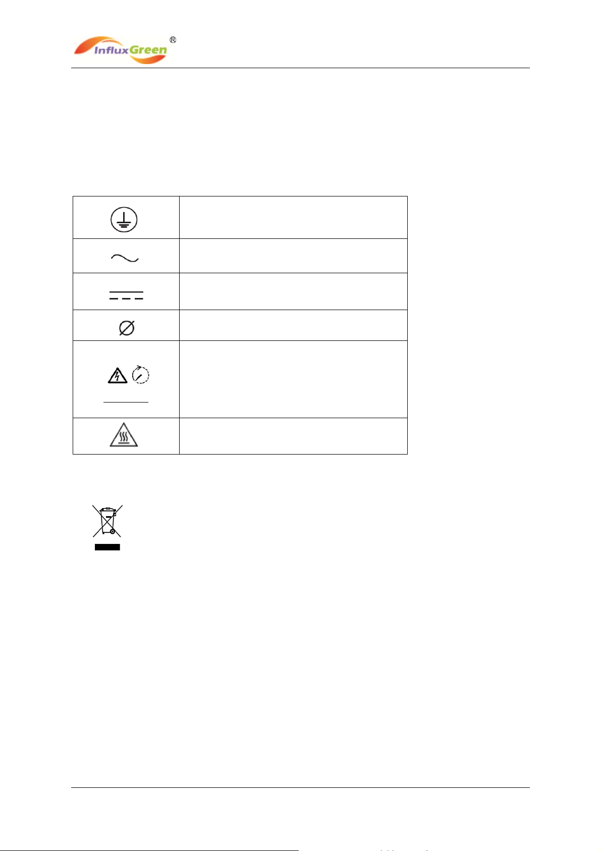
The equipment is provided with several labels, some of them with a yellow background, and
these are related to safety issues.
Make sure to read the labels and fully understand them before installing the equipment.
The symbols are:
Equipment grounding conductor (Main
grounding protective earth, PE)
Alternate Current (AC) value
Direct Current (DC) value
Phase
5minutes
To avoid risk of electric shock from energy
stored in capacitor, please wait for at least 5
minutes to access the conductor part of input
or output terminals of the inverter after it is
disconnected from the output of PV panel
and AC grid.
Caution: The temperature of metal enclosure
may be high during operation.
Disposal: Do not dispose of electrical appliances as
unsorted municipal waste, use separate collection
facilities. Contact you local government for
information regarding the collection systems
available. If electrical appliances are disposed of in
landfills or dumps, hazardous substances can leak
into the groundwater and get into the food chain,
damaging your health and well-being.

InfluxGreen Energy Pte Ltd
Model: IGSI-3 Phase Output Series Rev.0
5
CONTENT
1.OVERVIEW................................................................................................................... 6
2.INSTALLATION ........................................................................................................... 8
2.1 Package inspection ............................................................................................ 8
2.2 Selecting the place of installation ..................................................................... 8
2.3 Fixed on the wall .................................................................................................. 9
2.4 System diagram and connection label .............................................................. 11
2.5 Connecting to the AC grid (utility) ....................................................................... 12
2.6 Connecting to PV Panel (DC input) ............................................................................... 12
2.7 AC Output Protective Device ................................................................................................. 13
3.CONTROL PANEL FUNCTIONS .......................................................................................... 14
3.1 Operate the Function Key ................................................................................. 15
3.2 General LCD Display Information ........................................................... 17
4.INVERTER START-UP AND OPERATION ......................................................................... 18
5.COMMUNICATIONS .............................................................................................. 19
5.1 Data communications with RS232 ................................................................................... 19
5.2 Data communications with RS485 (optional) ................................................................ 20
5.2.1 RS485 Serial Port ...........................................................................................................20
5.2.2 RJ45 Connectors.............................................................................................................20
5.2.3 RS485 Daisy Chain .........................................................................................................21
5.3 Monitor Inverter ...................................................................................................................... 22
6.MAINTENANCE ............................................................................................................................. 22
7.TROUBLE SHOOTING ............................................................................................................... 22
8.SPECIFICATIONS ........................................................................................................................ 24

InfluxGreen Energy Pte Ltd
Model: IGSI-3 Phase Output Series Rev.0
6
1. OVERVIEW
1.1 Basic Features
The IGSI – 3 Phase Output Series of string PV inverter is one of the optimum designed
inverter on the market today, incorporating state-of-the-art technology, high reliability, and
convenient control features.
Advanced DSP control technology.
Utilize the latest high-efficiency power component.
Optimal MPPT technology.
2 independent MPP trackers.
Advanced anti-islanding solutions.
Maximum efficiency up to 98%, EU efficiency up to 97.6%.
THD~3%.
Power factor adjustable arrange:+/-0.9.
Safety & Reliability: Transformerless design with software and hardware protection.
IP65 protection.
Friendly HMI.
LED status indications.
Multi language LCD display, Human-Machine interaction through button.
RS485/RS232 communication interface.
PC remote control.

InfluxGreen Energy Pte Ltd
Model: IGSI-3 Phase Output Series Rev.0
7
1.1 Machine Overview
FrontView BottomView
Fig.1 Overview of inverter
RS232 outlet
A
C terminals cover
(AC terminals is inside)
RS 485 outlet
PV input

InfluxGreen Energy Pte Ltd
Model: IGSI-3 Phase Output Series Rev.0
8
Opening the package
After opening the package, please check the contents of the box. It should contain the
following accessories:
Item Name Quantity
1. Solar inverter 1 pc
2. Mounting frame 1 pc
3. Mounting screws and
blocks 6 pcs
4. Safety-lock screws 2 pcs
5. Socket head wrench 1 pc
6. DC socket assembly 1 set
7. Special RS-232 cable 1 pc
8. Instruction manual 1 pc
9. Monitor software(CD) 1 pc
10. Warranty sheet 1 pc
IGSI-xxxxDJ/3 series include:
IGSI-5000DJ/3, IGSI-6000DJ/3, IGSI-8000DJ/3, IGSI-10000DJ, IGSI-12000DJ

InfluxGreen Energy Pte Ltd
Model: IGSI-3 Phase Output Series Rev.0
9
2. INSTALLATION
WARNING: The electrical installation of the IGSI “J” series inverter must be performed in compliance
with applicable local and national standards and laws.
WARNING: The connection of IGSI “J” series inverter to the AC grid must be performed only after
receiving authorization from the utility that operates the grid.
2.1 Package Inspection
The customer is encouraged to perform the following checks:
Inspect the package box for apparent damage, such as holes, cracking or any sign of
possible damage to its contents.
Describe any damage or shortage on the receiving documents and have the carrier sign
his/her full name.
Open the package box and inspect the contents for internal damage. While unpacking,
be careful not to discard any equipment, parts or manuals. If any damage is detected,
call the delivering carrier to determine the appropriate action. Save all shipping material
for the event the carrier sends an inspector to verify damage!
If the inspection reveals damage to the inverter, please call your local supplier or the
authorized distributor. They will determine if the equipment should be returned for repair.
They will also provide instructions on how to get the equipment repaired;
It is the customer’s responsibility to file a claim with the carrier. Failure to file a claim with
the carrier may void all warranty service rights for any damage;
Carefully store the original packaging of IGSI “J” series inverter since it shall be used in
case it is necessary to ship it for repair.
2.2 Selecting the place of installation
Place of installation should be selected based on the following considerations:
IGSI “J” series inverters shall be set at a suitable height from the ground to enable easy
readout view of the display and the LEDs.
Select a well ventilated place sheltered from direct sun radiation. Choose a place that
allows fluent air flow around the unit.
Allow sufficient room around the unit to enable easy installation and removal of the object
from its mounting surface.
InfluxGreen Energy Pte Ltd
Model: IGSI-3 Phase Output Series Rev.0
10
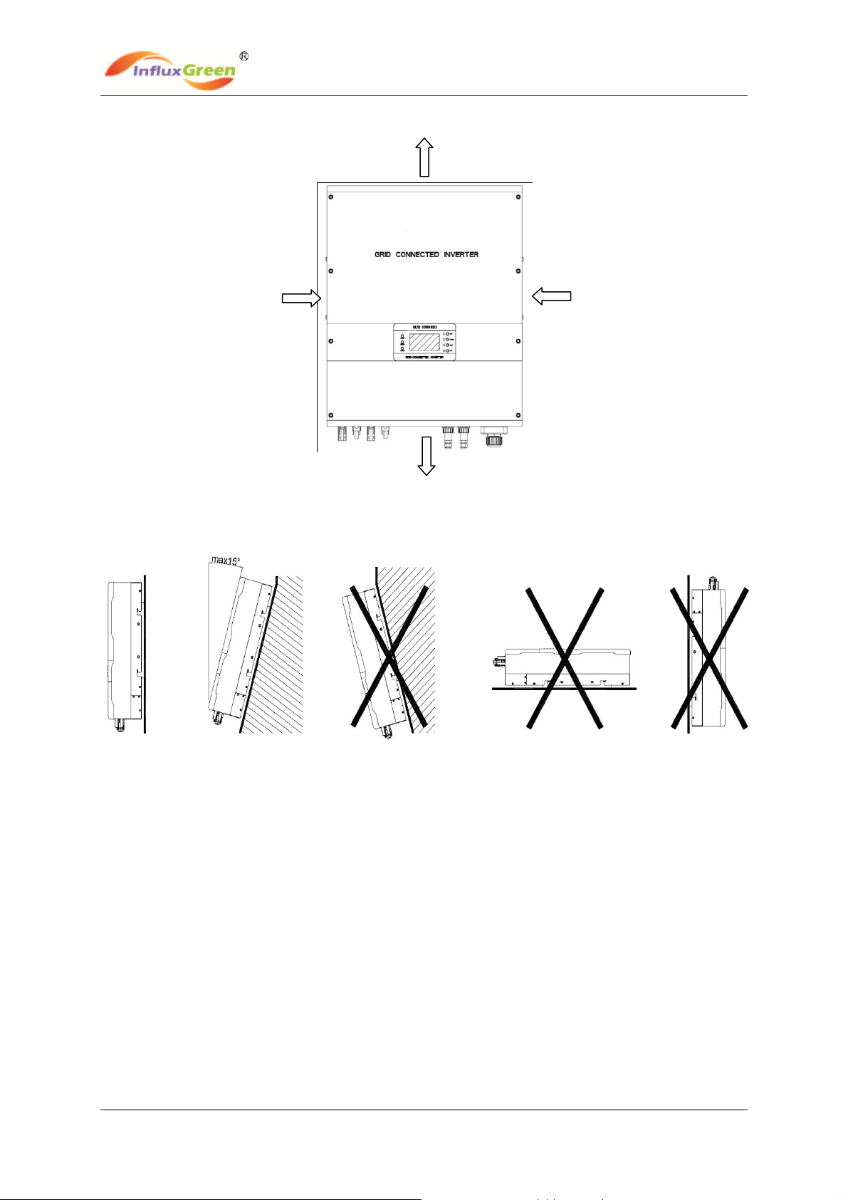
The following figure shows the recommended minimum clearances around the inverter:
Fig.2 Minimum clearance around inverter
Fig.3 Recommended installed position of the inverter
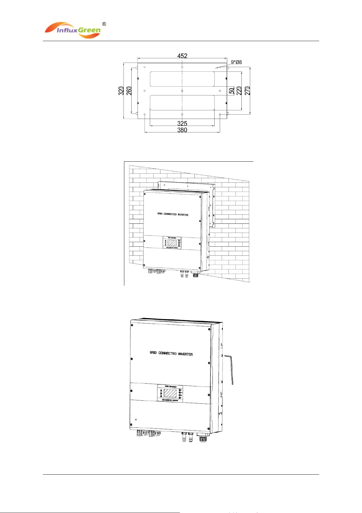
2.3 Fixed on the wall
Step1: Drill 6 or 9 holes as illustrated in the Fig.4
Step2: Fix the mounting frame as illustrated in the Fig.5 by the screws, and then hang the
inverter on the mounting frame.
Step3: Fix safety-lock screws at left side and right side as illustrated in Fig.6 with the
attached socket head wench.
Step4: Check the installation conditions.
50CM 50CM
50CM
50CM
InfluxGreen Energy Pte Ltd
Model: IGSI-3 Phase Output Series Rev.0
11
Fig.4 The size of mounting frame for IGSI-xxxxDJ/3, IGSI-10000DJ, IGSI-12000DJ
Fig.5 Hang inverter to mounting frame
Fig.6 Fix safety-lock screws
InfluxGreen Energy Pte Ltd
Model: IGSI-3 Phase Output Series Rev.0
12
The customer is encouraged to perform the following checks:
Do not install the solar inverter on a gradient surface.
Check the upper straps of solar inverter and ensure it to fit on to the bracket.
Ensure safety-lock screws (M5 socket head cap screws) to insert into the mounting
frame through inverter’s heat-sink.
Check the secure mounting of the solar inverter by trying to raise it from the bottom. The
solar inverter should remain firmly attached.
Choose a strong mounting wall to prevent vibrations while inverter is operating.
2.4 System Diagram and Connection Label
The IGSI “DJ/3” series are three-phase solar inverters with two independent channels of
MPPT input. They are designed to convert the direct current generated by PV panels into
three-phase 400Vac 50Hz alternating current for delivery into the AC grid.
The IGSI “DJ/3” series can be used in an on-grid PV system to produce electricity.
The installation of the IGSI “DJ/3” series and their connection to the AC grid shall be done in
accordance with local regulations and may require the installation of adequate electricity
consumption measuring devices.
The IGSI “DJ/3” series only operates when it is connected to the AC grid and cannot
operate as a stand-alone unit.
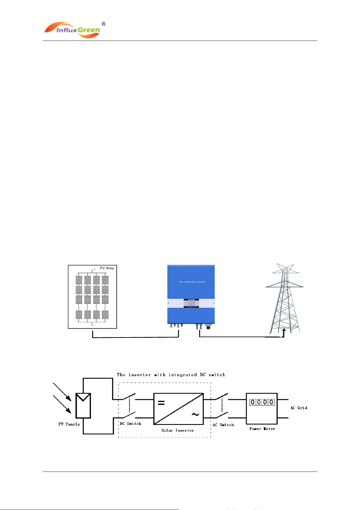
The simplified connection diagrams of the inverter are as figures 7 & 8 below.
Fig.7 The PV system diagram 1
Fig.8 The PV system diagram 2
InfluxGreen Energy Pte Ltd
Model: IGSI-3 Phase Output Series Rev.0
13
NOTE: Ensure that the IGSI-xxxxDL/3 inverter is not exposed to direct sun radiation or
other external heat sources, including heat from units below it (see fig.6). At times, the
heat generated by the inverters installed at the bottom rows could increase the ambient
temperature and this may be detrimental to the inverters located in the top rows. At temperature above
50°C, output power of the top row units could be derated. Derating is more significant in case of high
output power and high ambient temperature. For proper cooling, do make sure to allow unobstructed
air flow at installed location (for instance, never with the front panel facing a solid surface).
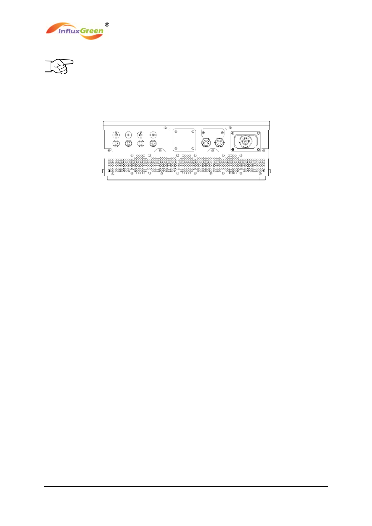
Fig. 9 Connections on the bottom of the inverter
A. PV Panels: Provide DC power to inverter.
B. Solar inverter: Converts DC (Direct Current) power from PV panel(s) to AC (Alternating
Current) power. As the Inverter is grid-connected, it controls the current amplitude
according to the PV Panel power supply. The PV inverter always tries to convert the
maximum power from your PV panel(s).
C. DC Switch and AC Switch: “DC switch” is located between PV Panels and solar inverter
while “AC Switch” located is between AC Grid (Utility) and solar Inverter. They are
simplified in this diagram. Usually, they may consist of electrical breaker, fuse and/or
connecting terminals. To comply with local safety standards and codes, the connection
system should be designed and implemented by a qualified technician. The solar inverter
also has an option of an integrated DC switch demonstrated in dashed border in Fig.6. –S
suffix indicates the inverter is integrated a DC switch in PV input side.
D. AC Grid (Utility): Referred to as “grid” in this manual, is the way your electric power
company provides power to your place. Please note that Inverter can only connect to
low-voltage systems (namely, 400Vac, 50Hz).
E. PV INPUT: Connected to PV Panels by the attached terminals.
F. RS232: Connected to monitoring computer by special RS232 cable provided.
G. RS485: daisy-chain communication for one or more inverters.
H . AC TERMINAL (three blocks in right hand): Connected to AC Grid.
Note: There is an option of an integrated switch box that includes DC switch, AC switch,
DC fuse, AC fuse, DC SPD and AC SPD devices as an option. Such a product is also
readily available from your local market.
2.5 Connecting to the AC Grid (Utility)
A. Measure AC grid (utility) voltage and frequency. It should be 400VAC, 50Hz, three-phase.
B. Open AC Switch between solar inverter and AC Grid (Utility).
C. Open AC terminals cover and connect AC wires on AC terminals as follows. It is
recommended that the tightening torque for the terminals be 0.56Nm. It is necessary to
terminate the PE terminal with the main grounding protecting earth by a suitably sized cable.

InfluxGreen Energy Pte Ltd
Model: IGSI-3 Phase Output Series Rev.0
14
Fig. 10 AC terminals under AC terminals cover
Model IGSI-5000DJ/3 IGSI-6000DJ/3 IGSI-8000DJ/3 IGSI-10000DJ IGSI-12000DJ
Cable(Cu) ≧4mm2≧4mm2≧4mm2≧4mm2≧4mm2
Micro-Breaker 25A 25A 25A 25A 25A
WARNING: When making the electrical connections adhere strictly to the procedures to
avoid exposure to dangerous voltages.
WARNING: Use suitable low-impedance cables to connect the inverter to AC disconnect.
WARNING: IGSI “DJ” 3-phase series inverter shall be connected to AC disconnect by means
of a five-wire cable: three phase cables, one neutral cable and a yellow-green cable for
ground (PE).
Connect the 5-wire cables as follows:
Terminal for Protective Earth PE
Terminal R for Line R,
Terminal S for Line S.
Terminal T for Line T.
Terminal N for neutral.
Fig.11 - Terminations for AC cables connections
WARNING: Do not reverse any phase and neutral as this may make the system unsafe to
run and cause malfunctioning.
InfluxGreen Energy Pte Ltd
Model: IGSI-3 Phase Output Series Rev.0
15
2.6 Connecting to PV Panel (DC input)
A. Under any condition! Make sure the maximum open circuit voltage (Voc) of each PV
string is less than 900VDC for the IGSI-xxxxDJ/3, IGSI-10000DJ & IGSI-12000DJ. The
length of input cable must be less than 30m. Generally, at the lowest ambient
temperature, the Voc of PV string is the highest.
B. Use the attached connectors for the PV array termination.
C. Open the DC Switch and connect the positive and negative terminals from the PV panel
to the DC switch, and then to the positive (+) terminals and negative (-) terminals on the
solar inverter. Each DC terminal on the inverter can withstand up to 40Adc.
D. When connecting the PV panels to the DC Switch, and the DC Switch to the terminals of
the inverter, please ensure that the polarity is correct.
Incorrect polarity connection could permanently damage the unit.Please confirm
the short-circuit current of the PV string. The total short-circuit current of the PV string
should be less than the inverter’s maximum DC input current.
E. High voltages exist when the PV panel is exposed to the sun. To reduce risk of electrical
shock, avoid touching live components and treat all connecting terminals with proper
care.
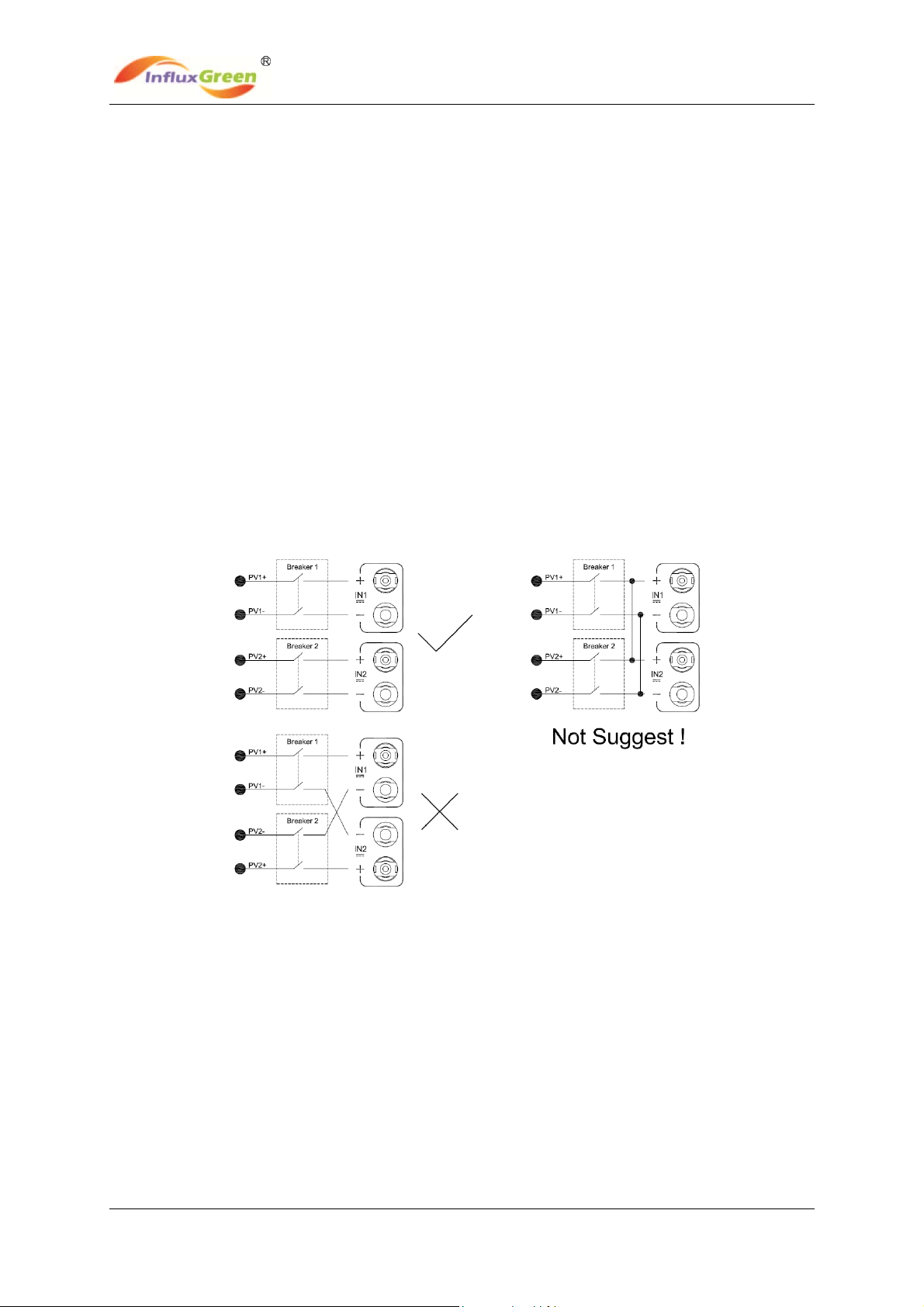
F. To avoid the Electro Magnetic Interference of inverter to the surrounding equipment,
please see below the recommended connections.
Note: Ensure that photovoltaic field voltage polarity matches the “+” and “-” symbols. Before
connecting the IGSI “DJ” series inverters with the photovoltaic field, it is recommended to
check, using a proper gauge, that the polarity value and the voltage allowed value between
positive and negative contacts are correct.
InfluxGreen Energy Pte Ltd
Model: IGSI-3 Phase Output Series Rev.0
16
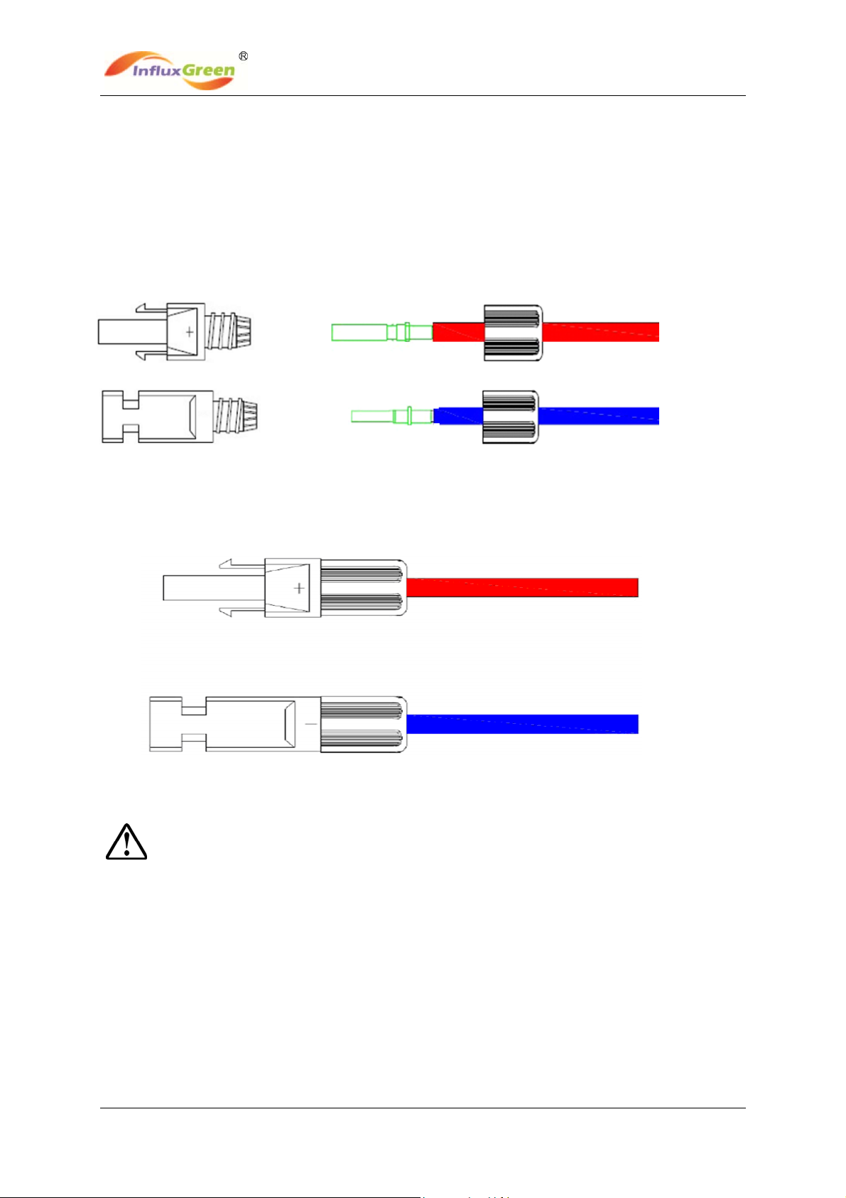
2.6.1 Assemble the DC connector
2.6.1.1 Strip the cable 6-8mm,then connect the bare wire core into the core tube of
connector.
2.6.1.2 Crimp the contact barrel by using a hex crimping die. Put the contact barrel with the
stripped cable in the corresponding crimping notch and crimp the contact.
2.6.1.3 Insert the core tube into the slot of the connection until you hear the locking sound,
indicating in connection is in place.
2.6.1.4 Insert contact cable assembly into back of the male and female connector. Tighted
the nuts accordingly towards the opposite direction. The assembly is complete.
5
WARNING: Shock hazard! Before removing the panel, disconnect the inverter at both the AC
and DC side and allow at least 5 minutes for the internal capacitors to discharge.
InfluxGreen Energy Pte Ltd
Model: IGSI-3 Phase Output Series Rev.0
17
3. OPERATION METHOD
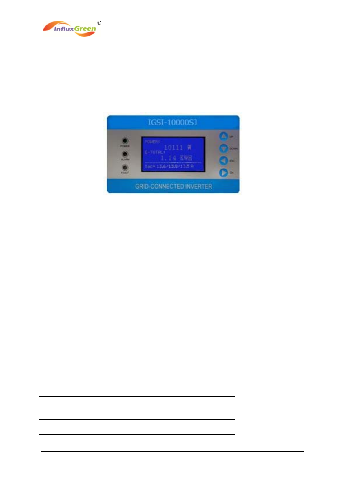
3.1 Control Panel
There is a LCD screen, three LEDs and four function keys on the front panel of the solar
inverter. The LCD and LED provide the status of your Inverter. You also can use the function
key as a simple control for scrolling and viewing data.
Fig. 12 Control panel
A. LCD Screen: Display the operating data and conditions, warning/error codes and
relevant inverter information.
B. The model of inverter (for example,IGSI-1000SJ)
C. ALARM LED: Indicates the alarm of the inverter.
D. POWER LED: Indicates the inverter is running normally.
E. Fault LED: Indicates the fault of the inverter.
F. Function Key: Shall be used to set different parameters and display language for the
inverter.
G. Description of inverter
Note: To save power, the LCD display’s backlight automatically turns off after 10 seconds.
There are 4 buttons on the panel’s function keys: UP, DOWN, ESC ,OK
UP button: Move cursor to up or increase the values
DOWN button: Move cursor to down or decrease the values.
ESC button: Exit current screen or selection
OK button: Confirm the selection.
LED indicators
Information List Green LED Yellow LED Red LED
Wait State FLASH OFF OFF
Fault Revover OFF ON OFF
Normal State ON OFF OFF
Fault State OFF OFF ON
Permanent State ON OFF OFF

InfluxGreen Energy Pte Ltd
Model: IGSI-3 Phase Output Series Rev.0
18
Wait State: Inverter is waiting to check state for the period of the reconnection time. In
this state, the PV voltage is more than 250V and the grid voltage value is
between the max and min limit. If out of range, the inverter will go to Fault
State or Permanent State.
Fault Recover: Inverter is on the process of circulating in take place mistake or
breakdown, break down Inverter to re- combine a net after the relief
Normal State: Inverter feeds to grid energy from PV panel as much as possible
according MPP trackers. Inverter will go to Fault State or Permernent
State if any error or fault occurs.
Fault State: Inverter has occurred some recoverable error
Permanent State: Inverter has occurred some unrecoverable error. It will stay in Permenent
State. You should take some measure according the error code.

InfluxGreen Energy Pte Ltd
Model: IGSI-3 Phase Output Series Rev.0
19
3.2 Operate the Function Key
To view the operating data of the inverter, you can press the Function Key. Of course, the
data also will automatically and periodically display. To set different display contrast and
display language for the inverter, please carefully refert to the following chart.
3.2.1 LCD Commissioning setup operation steps
System Time Setting
Main
Interface
Press OK key
Press DOWN key
Press UP/DOWN key Set your
Date (YY/MM/DD ) and Time&
System Time Setting (Complete)
Time Setting
Complete
Time Setting
Complete
Press OK key
Press ESC key
Press ESC key
MAIN MENU
System setting
System setting

InfluxGreen Energy Pte Ltd
Model: IGSI-3 Phase Output Series Rev.0
20
System Language Setting
Audible Alarm Setting
MAIN MENU
Main
Interface
Press OK key
Press OK key
Select your
language
Language Setting
Complete
System Setting
Main Interface
Press UP/DOWN key
Press OK key
Press ESC key twice
System setting
Main
Interface
Press OK key
Press UP/DOWN
key Set ON/OFF
Audible Alarm
Setting Complete
System Setting
Main Interface
Press OK key
Press OK key
MAIN MENU
Press OK key
Press ESC key twice
System setting
This manual suits for next models
6
Table of contents
Popular Inverter manuals by other brands

Sunnydaze Decor
Sunnydaze Decor AMP-P003CR manual

SMA
SMA Sunny Island 2012 Technical description

Sensata
Sensata Magnum-Dimensions MagnaSine MS-G Series owner's manual

Trinabess
Trinabess Trinahome T Series user manual

Clenergy
Clenergy PV-ezRack SolarFloating I installation guide

MDS Power
MDS Power MHI-24/5600DN owner's manual


