Mase MPF 16-22 User manual

MPF 16 - 22
Tipo modello
N° matricola
Codice
Rev.0 A.A. 06 - 02 - 08
cod.42878
GRUPPO ELETTROGENO MANUALE DI USO E MANUTENZIONE I
GENSET USE AND MAINTENANCE MANUAL GB
ELEKTROAGGREGATEBRAUCHSANWEISUNG UND
WARTUNGSVORSCHRIFTEN D
GROUPE ÉLECTROGÈNE MANUEL D’UTILISATION ET D’ENTRETIEN F
GROUPE ÉLECTROGÈNE MANUAL DE USO Y MANTENIMIENTO E

MPF 16-22
- 2
GB
GB
DEFINITIONSUSED................................................ 4
1 GENERALINFORMATIONS ............................ 6
1.1 Conformuse ................................................... 6
1.2 Residualrisks................................................. 6
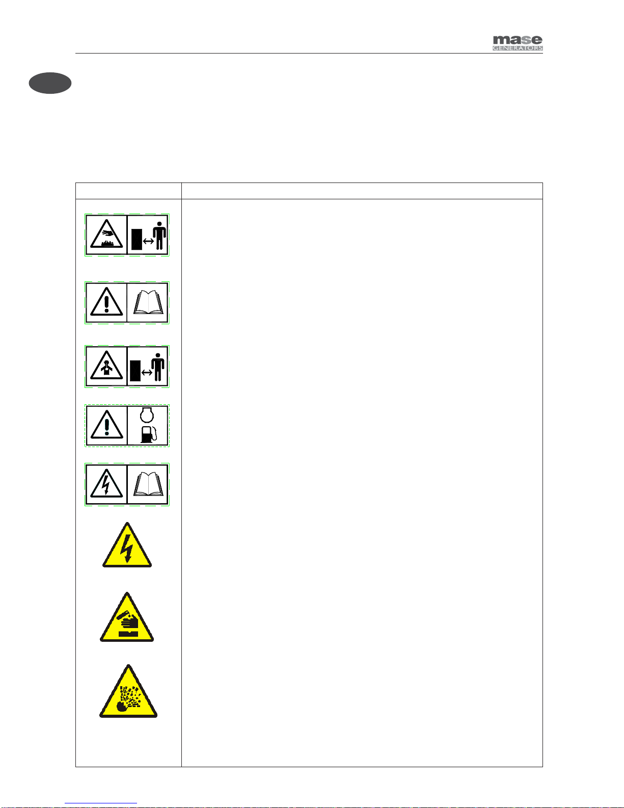
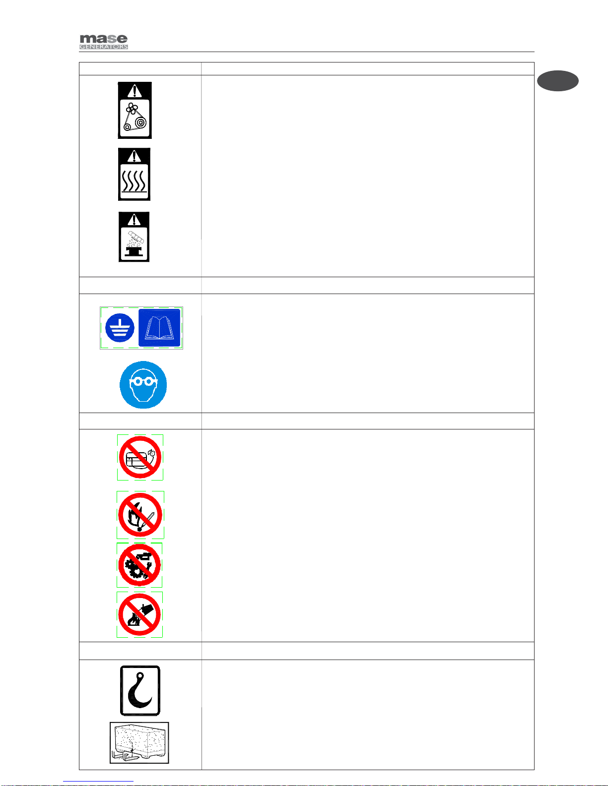
1.3 Symbolsonthegeneratorgroup ..................... 7
1.4 Position of safety labels.................................. 8
1.5 Generaldangerinformation ........................... 10
1.5.1 Dangerofentanglement ................................ 10
1.5.2 Dangerofburns ............................................ 10
1.5.3 Dangerofharmtohearing............................. 11
1.5.4 Dangerofintoxication ................................... 11
1.5.5 Dangeroffireorexplosion ............................ 11
1.5.6 Dangeriffailingtousepersonalprotection
devices ......................................................... 12
1.5.7 Dangercausedbytheengine starting........... 12
1.5.8 Dangerofelectromagneticradiation.............. 12
1.5.9 Dangerofelectrocution ................................. 12
1.5.10Dangerresultingfrombadstorage ............... 12
1.6 Referencedocuments................................... 13
1.7 Referenceregulationsandlegislativeprovisions. 13
1.8 Marking ........................................................ 13
1.9 Identificationofthegeneratorunit ................. 13
2 GENERALCHARACTERISTICS .................... 14
2.1 Configurations............................................... 14
2.2 Compositionofgeneratorunit ....................... 14
2.3 Instrumentpanel........................................... 14
2.4 Table oftechnical characteristics.................. 15
2.5 Noiseemission............................................. 16
3 INSTALLATION............................................. 17
3.1 Generalinstallationcriteria ........................... 17
3.2 Importantinformation .................................... 17
3.2.1 Inspectionofmaterials.................................. 17
3.2.2 Safetystandardsfordieselengines .............. 17
3.2.3 Foundations ................................................. 17
3.3 Exhaust plant ............................................... 17
3.3.1 Exhaustpipe ................................................ 17
3.3.2 Exhaust pipe design ..................................... 17
3.4 Ventilation .................................................... 17
3.5 Fuel system ................................................. 17
3.6 Electricalconnection .................................... 18
3.6.1 PowerCablesizes........................................ 18
3.6.2 Powercablelayng ........................................ 18
3.6.3 Earthing........................................................ 18
3.7 Outdoorinstallation....................................... 19
3.8 Indoorinstallation ......................................... 20
4 USINGTHEGENERATOR ............................. 21
4.1 Preliminary checks....................................... 21
4.2 Refuelling...................................................... 21
4.3 Battery ......................................................... 21
4.4 Starting ........................................................ 21
4.5 Usingthegenerator ...................................... 22
4.6 Stopping....................................................... 22
4.7 Emergencystop ........................................... 22
5 PROTECTIONSANDWARNINGSIGNALS .. 22
5.1 Protectionagainstshort-circuitandoverload. 22
5.2 Engineprotectionmodule ............................. 23
6 MAINTENANCE ............................................. 24
6.1 Preamble...................................................... 24
6.2 Ordinaryenginemaintenance ....................... 24
6.3 Engineoil change ......................................... 24
6.3.1 Changingoilfilter .......................................... 24
6.4 Changingfuel filter ....................................... 24
6.4.1 Systembleeding........................................... 24
6.5 Airfiltercleaning/replacement....................... 25
6.6 Coolantcheck .............................................. 25
6.7 Battery check............................................... 25
6.8 Suctiongridandventcleaning ...................... 26
6.9 Scheduledmaintenancetable....................... 26
6.10 Periodofinactivity ........................................ 26
7 ANOMALIES,CAUSESANDREMEDIES ...... 27
7.1 How to order the spare sparts....................... 27
8 TRANSPORT,STORAGE,LIFTINGAND
HANDLING................................................... 28
8.1 Transportandstorage................................... 28
8.2 Liftingandhandling....................................... 28
8.2.1 Liftingandhandlingwithcrane ...................... 28
8.2.2 Liftingandhandlingwith forklifttruck............. 28
8.3 Versionwithslow-drawntrailer...................... 29
9 GUARANTEEANDRESPONSIBILITY........... 30
9.1 Guarantee .................................................... 30
9.2 Limits of responsibility .................................. 30
10 DISPOSAL .................................................... 30
10.1 Disposalofthewastematerialsderivingfrom
maintenanceandscrapping .......................... 30
11 WIRINGDIAGRAM ....................................... 31
11.1 Wiringdiagram ............................................. 31
INDEX

MPF 16-22
- 3
GB
GB
This manual has to be preserved for all through life of the
gen set to which ago reference
Thankyouforhavingchosenaproduct mase.
Asaleadinggeneratormanufacturer,maseGeneratorsoffersawiderangeofgeneratorswithanoutputfrom1KVA
portablegeneratorsto1600KVAunitsforspecialapplications.
Foundedin1970,theCesena-basedcompanyextendsoveraareaof16,000squaremeters,includinga9,000sq.mtr.
manufacturingfacility.
maseGeneratorsbeganasacompanyproducing500Watt,lightandcompactportablegenerators.Thesegenerators
madetheMaseGeneratorsnamewellknownthroughouttheworld.MaseGeneratorsisaleaderinhigh
quality,reliableproducts,andinnovativeresearchperformedbyResearchandDevelopmentDepartment.
Thegeneratoryouhavepurchasedisthefruitofyearsofexperienceinthesectorandforthemodernconception,the
strongsizing, thematerials employees,the continuousupdatings, constitutes aneffective answerto the operators’
demandsofthesector.
This Manualinstructions will furnish you usefulinformationand precious suggestions so you canfully exploit
allthe possibilities that thegenerators offers you.
If any partof themanual resultedincomprehensible, pleasecontactus.
Intorenew ourthankswe cordiallygreetyou.
MASEGENERATORSSPA
MASE GENERATORS S.p.A. ViaTortona, 345
47023 Cesena (FC) Italy
Tel.+39-0547-354311 Fax.+39-0547-317555
Technicaldata,informations,layouts of the texts and graphic preparations: edited by the Technical Office
MaseGenerators
THEMASEGENERATORSSPA, RESERVESALLTHERIGHTS ONTHEMANUALPRESENT. ANYTOTAL
ORPARTIALREPRODUCTIONISPERMITTEDWITHOUTWRITTENAUTHORIZATIONOFTHEMASE
GENERATORSSPA.

MPF 16-22
- 4
GB
GB DEFINITIONSUSED
- Theterms used arecurrenttechnical terms, andwhereconsidered necessary themeaning is described below
- Generator
Anassemblyofaninternalcombustionpistonengineandanalternatecurrent,synchronous,2-4pole,self-excited
generator,joinedtogether tocreateastationfor self-productionofelectricalenergy.
- Usersystem
Composed of the power supply circuits of the user equipment, including the relevant sectioning, handling,
breaking,transformation, protection, etc.devices which donotform partofthe
production, transmission and distribution systems.
- Category 1 electrical system
A system where the rated voltage is greater than 50 V and smaller than 1000 V including alternate current.
- Load
Asetofnumericalvaluesofelectricalandmechanicalmagnitudeswhichcharacterisetherequirementsimposed
on a rotary machine by an electrical circuit or by a mechanical device at a certain instant.
- Thermal switch
Main cut-out and breaking device made up of a switch which opens automatically by thermal effect.
- Differentialswitch
Maincut-outand breaking device made up of a switch which opensautomaticallybydifferential effect.
- Skilled person
Apersonwithtechnicalknow-howorsufficientexperiencetoallowhimtoavoidthedangersinherentinelectricity.
-masespecialised personnel
Apersonabletoevaluatethejobassignedtohimandrecognisethepossibledangersonthebasisoftrainingat
themasetrainingcentres,withprofessionalexperienceandknowledgeoftheequipmentinquestionandofthe
possibledangersderivingintheeventofnegligentbehaviour.
- Supplier
A body (e.g. manufacturer, agent, installer) which supplies the equipment or services relating to the machine.
- Control
Control action by which an output variable of the controlled system (controlled variable) is affected by an input
variableof the controllingsystemin order toachieve a certain goal.
- Manual control
Controlwherethechangeofavariablehandledisproducedbyapersonthroughmanualintervention
- Automaticcontrol
Controlwherethechangeofavariablehandledisproducedbyacontrollingdevice(automaticcontroller)without
theinterventionofaperson
- Danger
Sourceofpossible harm or damage to health
- Protection
Guard or protection device as safety measuretoprotect persons from a present orpotentialdanger.
- Casing
Partintended to assure protectionofthe equipment against specificoutsideinfluences and protection inevery
sense against contacts.

MPF 16-22
- 5
GB
GB
- Connection in bad state
Thelivepartsarenotfullycoveredwithinsulationremovablebydestructiononly,theconnectionsarenotsecure
becauseof unstable tighteningof the partsand a developmentofoxide betweentheparts.
- Directcontact
Contact of persons or animals with live parts
- Controlcircuit
Circuitusedto control machine operation
- Equipment
Generaltermwhichcomprisesmaterials,devices,equipment,accessoriesandsimilarusedinconjunctionwith
an electrical installation
Indicatesthatparticularattentionmustbepaidinordertopreventseriousriskswhichcould
lead to death or possible harm to the health of personnel.
Aconditionwhichmayoccurduringthelifetimeofaproduct,systemorplantconsidered
atrisk regarding damage to persons, property, the environmentoreconomicloss.
Indicatesthatparticularattentionmustbepaidinordertopreventseriousconsequences
whichcouldresult in damagetotangible goods, such astheresources or theproduct.
Instructionsofparticularimportance.
Carefullyconsult this manual before using or carrying outanyoperation on the generator.
#Theroutinemaintenance operations, must be carried out by qualified personnelwhohavethe
appropriateequipmentandprotections.

MPF 16-22
- 6
GB
GB 1GENERALINFORMATIONS
1.1 CONFORM USE
Thegenerator is suitable forindependent production of electricalenergywithin the voltageandwattage limits
declaredby themanufacturer.
Any other use outside the already stated field of use is prohibited: the generator is intended for industrial use.
Thegenerator has beendesignedto operate independently(withoutoperator) if notfor sporadic checks.
The limits of use are:
- operatingtemperature:-5°+40°
- relative humidity: 30% - 90%
- thegeneratorissuitableforoperationoutdo;itmaynotbeoperatedinclosedenvironmentssincethegenerator
producesexhaustgas.
Inside installation is subject to approval by maseor an installer authorised by mase.
Arbitrarymodifications to the machine areprohibitedfor safety reasons.
Original spare parts must be used on pain of losing machine conformity.
All the operations that require dismantling of special parts may only be carried out by technicians authorised by
thelocal dealer orthemanufacturer.
Only masetechnicians or personnel trainedbymasehavethe necessary knowledge of thegenerator and the
special equipment as well as the experience to carry out any operation in the most economical and reliable way.
1.2 RESIDUAL RISKS
The generator has been designed taking into account the safety regulations set out in the EC directives and
standards;nonetheless, the following residualrisksremain:The generator has beendesigned taking into account
the safety regulations set out in the EC directives and standards; nonetheless, the following residual risks
remain:
- injury caused by contact with hot parts during maintenance.
- injury caused by electrocution during maintenance on the electric panel.
- risks connected with long periods of exposure to the noise of the generator.
- risks due to contact with the generator lubricants during maintenance.
- risks due to the fire hazard the fuel represents.
Becauseof the typical intrinsic danger of theGenerators,you are reminded that, although the generatorhas
beendesigned, constructed and tested in accordance withthesafety regulations, only proper and carefuluse
can guarantee full safety; to this end, the various precautions to be taken during use of the Generator are listed
below.

MPF 16-22
- 7
GB
GB
cod. 41781
cod. 42119
cod. 42118
cod. 41775 cod. 41777
cod. 42349
cod. 42351
STOP
cod. 41776
cod. 42353
cod. 42346
cod. 42861
cod. 42348
cod. 42119
cod. 42112
Cod.46223
1.3 SYMBOLS ON THE GENERATOR GROUP

MPF 16-22
- 8
GB
GB
EE
LL
STOP
E
S
D
IE
S
I
D
1.4 POSITION OF SAFETY LABELS
• These labels warn the user of any danger which may cause serious injury.
Carefullyread the meaningand the precautionsdescribedin thismanual.
• Ifthelabel detachesorbecomes illegible,replaceitwitha newonewhich canberequestedfroman authorised
masedealer.
Danger Symbols Meaning
- Cautiontoavoidburns,donottouchduringoperation.
Theexhaustmanifoldandtheengine,payattentiontothelabelsonthegenerator.
- Leavethe engineto cooldown beforestoring itindoors.
- ReadandunderstandtheUseandMaintenanceManualbeforestartingthegenerator.
- The maseSpA has been designed so as to guarantee safe and reliable operation
providedthattheinstructionsarefollowed. Otherwise, personalinjuryordamageto
the equipment may result.
- The exhaust gases contain toxic carbon monoxide.
- Neveroperatethegeneratorinaclosedspace.
- Provideforadequateventilation.Ifinstalledindoors,scrupulouslyobservetheventilation
regulations.
- Thefuels are highlyflammable and incertainconditions also explosive.
- Fillupinawell-ventilatedareawiththeengineoff.
- Do not smoke or create sparks while filling up.
- Immediatelyclean off anyfuel leaks.
- Dangerof electric discharge: consultthemanual.
- Dangerofpossiblecorrosiveacidleaks.
- Dangerofexplosion.

MPF 16-22
- 9
GB
GB
Danger Symbols Meaning
ProhibitionSymbols Meaning
- The connections to an emergency electric network must be carried out by specialised
electricians in compliance with the relevant regulations in force. Improper connections
may cause current feedback from the generator to the electrical lines connected. These
current feedbacks may cause electroconduction to the people working for the electricity
company or who come into contact with the lines during the failure. Moreover, once the
line has been restored, the generator may explode, burn or cause fires in the electrical
system of the facility.
- No smoking or use of open flames.
- Do not clean, lubricate, repair or adjust moving parts.
- Donot extinguish fireswithwater, use homologatedextinguishers.
- Dangerofentanglementandcutting:
Presence of rotating parts, pulleys, belts and fan.
- Dangerofburns:Hotsurfaces.
- Dangerof burns: Possibilityof pressurised hotwater
expulsion.
ObligationSymbols Meaning
- Obligationtoconnect the generator to earth.
- Obligation to wear eyes protection.
InformationSymbols Meaning
- Indicates the location of a point of the lifting hook of the generator.
- Indicates the location of the centre of gravity for the lifting with fork.

MPF 16-22
- 10
GB
GB
1.5 GENERAL DANGER INFORMATIONS
• It is recommended to learn how to stop and operate all the controls.
• Donotallowunqualifiedpersonneltousethegenerator.
• Even though the generator is protected, do not stand near it.
• Donot removethelabels foranyreason andrequestreplacement ifnecessary.
• BeforestartingtheGeneratororbeforestartinganylubricationormaintenanceoperation,itisessentialthatthe
personnel responsible has read and understood all the WARNINGS, CAUTION and DANGER notices in this
manualandintheadditionaltechnicaldocumentationprovided.
• Beforeanyoperationonthegenerator,ensurethattheprimaryengineisnotrunningandthatnopartsaremoving,
andpostasignsayingDONOTSWITCHONorsimilaratthestartswitchorthecontrolsbeforecarryingoutthe
maintenanceorrepairworkonthegenerator.
• Nevertheless,themanufacturercannotforeseeallthepossiblecircumstanceswhichmayleadtopotentialrisks
intheeffectiveconditionsofuseoftheGenerator.
Anyoperationsand/orproceduresformaintenancenotexpresslyrecommendedorindicatedintheusermanuals
mustalwaysbe notifiedto andapprovedbythemanufacturer.
Intheeventthataprocedurenotspecificallyrecommendedneedstobeapplied,theuserisresponsibleforassuring
that such procedure is safe and does not cause harm to persons.
• Themanufacturer declinesall responsibilityfor damagetopersons orthings derivingfrom inobservanceof the
safetyregulations.
• Carefullyexaminethe safetywarningplatesonthe generatorandrespecttherelevant instructions.
1.5.1 DANGER OF ENTANGLEMENT
• Donotremovetheoriginalprotectionsfromanyoftheexposedrotatingparts,hotsurfaces,airintakes,beltsand
liveparts.
• Donotcarryoutanymaintenanceoperation withthegeneratorrunning.
• Donotwearflappinggarments,suchasscarves,foulards,bracelets,etc.andallgarmentsmustbetiedwithelastic
at the edges.
• Donot clean or carry out maintenanceonmoving parts
1.5.2 DANGER OF BURNS
• Donot permit unskilled persons or withoutadequatetraining to use the generator.
• Do not permit children or animals to approach the generator when it is in operation.
• Nevertouchthe exhaust, the relevant protection or theenginebody when the generator is running orstillhot.
• Donot leanagainst or siton thegeneratorfor anyreason whatsoever.
• Identifythepositionofthefireextinguishersorotherprotectionandemergencydevicesandlearntheirfunctioning.
• Identify any sources of danger such as fuel, engine oil or acid solution leaks, condensate in the drip caps, high
voltage,highpressure.
• Do not cause short-circuits by placing keys or tools on the batteries or on the cable fittings.
• The battery fluid contains sulphuric acid which is extremely corrosive and harmful to the skin. Always wear
protectiveglovesandbeextremelycarefultoavoidspillagewhenpouringtheacid.Intheeventofcontact,wash
theaffectedpartthoroughlywithrunningwaterandconsultaphysician,inparticularwhentheeyesareinvolved.

MPF 16-22
- 11
GB
GB
1.5.3 DANGER OF HARM TO HEARING
• Donotstandnear thegeneratorfor longperiodswithoutprotective earmuffssincehearing maybereduced.
Prolongedexposuretonoiseabove85dB(A)maycausehealthdisorders.Itisinanycaserecommended
to use appropriate protection systems (e.g. headsets, earplugs, etc. ).
1.5.4 DANGER OF INTOXICATION
• The exhaust gases contain toxic carbon monoxide.
• Neverusethegeneratorin tunnelsor inany placewith poorventilation. Ifindooruseisinevitable, itis essential
toprovideforproperandefficientventilationinordertopreventintoxicationofpersonsoranimals.
• Check that the engine exhaust is free and that the pipes allow evacuation of the exhaust fumes.
• Checkthattheexhaustgasesaredischargedtotheoutsideinasafepositionawayfromdoors,windowsandair
intakes.
1.5.5 DANGER OF FIRE OR EXPLOSION
•Alwaysturnoffthe enginebeforerefuelling.
•Do not smoke during refuelling.
• Refuelling must be carried out with extreme care, ensuring that fuel does not overflow from the engine tank
respectingthemaximumlevel.
•In the event of fuel spillage fromthetank, thoroughly dry and clean the partsinvolved.
• Check that there are no fuel leaks and that the pipes are undamaged.
• When refuelling has been completed, tightly close the fillercap
•Keepflammableliquids,matchesandotherexplosiveand/orflammableproductsawayfromthegenerator,since
thetemperature nearthe exhaustishigh duringoperation.
•Neverleaveflammableliquidsorclothssoakedinflammableliquidsinproximityofelectricalequipment(including
lamps) or parts of the electrical system.
•Thebatteriesdevelophydrogen,ahighlyexplosivegas.Itisrecommendednottosmokenorcausesparksinthe
vicinity,inparticularduringcharging.
• Do not obstruct the cooling air inlets/outlets.
•Intheeventof fire,use ahomologated fireextinguisher andnever usewater.
1.5.6 DANGER IF FAILING TO USE PERSONAL PROTECTION DEVICES
• Thepersonsresponsibleforhandlingmustalwayswearprotectiveglovesandsafetyshoes.
• Wearsafetyshoes andoveralls.
• Ifthe generatorneedsto belifted from theground, theoperatorsmust weara protective helmet.
• Immediatelychangewetoveralls.
• Useprotectivegloves.

MPF 16-22
- 12
GB
GB
1.5.7 DANGER CAUSED BY THE ENGINE STARTING
• Donot leavedisassembledparts, toolsor anything elsenot formingpartof thesystem on ornear the engine.
• Install the protections necessary for safety on the parts completing the system.
• Operate the generator on a flat surface as far as possible. For continuous operation, the maximum permitted engine
inclinationis20degrees.Greaterinclinationofthegeneratormightcausethefueltoleakoutorcauseproblemswithengine
oilpressure.
• Topreventtheriskoffireandforproperventilation,positionthegeneratoratleast1m(3ft)frombuildingsorotherequipment
duringoperation.
• Check the oil level by means of the dipstick.
• Check that all the electrical utilities are off so that the generator is not started on load.
• Checkperfectfunctioningofthedeviceswhichstopthegeneratorintheeventoffailureduetolowoillevel.
• Identifythe position ofthe emergency stopbuttons,switches and otheremergency systems onthegenerator.
• Learnthespecialemergencyproceduresrelativetotheinstallationinquestion.
1.5.8 DANGEROFELECTROMAGNETIC RADIATION
• Donotallowaccesstopersonswearingapacemakerbecauseofpossibleelectromagneticinterferencewiththedevice.
1.5.9 DANGER OF ELECTROCUTION
• Whenusingthegeneratoralwaysbearinmindthatinwetorveryhumidplacesandinconfinedconductionspacesitis
obligatorytocomplywithArticles313and318ofPresidentialDecreeNo.54727/04/55,aswellasChap.11SectionIV
oftheCEI64-8regulation.
• Immediatelychangewetoveralls.
• Insulatealltheconnectorsanddetachedwires.
• Donotleavethepowerterminalboardofthegeneratoruncovered;checkthattheelectricalpowerandauxiliaryservice
connectionshavebeenmadeproperly.
• Donotpowerloadswithavoltagedifferentfromthatdeliveredbythegenerator
• Do not spray water directly onto the electrical parts
• Do not clean the internal electrical parts with compressed air, since short-circuits or other faults may occur.
Donottamperwiththeactiveprotections,thermalswitchesanddifferentialmagnetothermalswitches.
• Intheeventofmalfunctioning,donotremovethepaneltoattemptrepairingit.Contactmasespecialisedpersonnel.
• Do not access the generator with wet hands, since it is a potential source of electric shock if improperly used.
• Takethenecessaryprecautionstopreventthedangerofelectrocution;checkthattheearthingsystemhasbeeninstalled
andconstructedinaccordancewithregulations.
• Forthesafetyoftheusers,theearthconnectionofthegeneratormustalwaysbecarriedoutpayingparticularattention
tothecable cross-section used. For the connection of the earthcableuse the dedicated terminal on the generator.
The manufacturer is not responsible for any damage caused by failure to earth the system.
1.5.10 DANGER RESULTING FROM BAD STORAGE
• Packedandunpackedgenerators mustbestored inacoolanddryplaceand neverexposedtobadweather.
• Avoidstackingpackedgeneratorstopreventthemfromfallingcausingdamageto personsand/or things.

MPF 16-22
- 13
GB
GB
KVA
Hz
Cos.Ø
VV
AA
Degrees of protection IP
°C
m
Performance class
year of manifacture
Rated power factor
Rated voltage
declared frequency
Mass Kg
Class of insulation
Temp. max of use
Altitude max. of use
Rated current
Rated power 3F
Code Serial n°
1
2
5
4
67
89
11
12
13
15
16
3
14
10
1.6 REFERENCE DOCUMENTS
Theinstructionsforuseprovidedwitheachgeneratorare
madeupofacollectionofdocumentsofwhichthismanual
representstheGeneralPart.Thefollowingdocumentsare
normallyprovidedseparate.
aECdeclarationofconformity.
bInstruction manual for use and maintenance of the
generators,
(thismanual).
cEngineuseandmaintenancemanual.
dListofmaseServiceCentres.
emaseWarranty certificate.
fWarrantycard.
1.7 REFERENCE REGULATIONS AND LEGISLATIVE PROVISIONS
Allmasegeneratorsaredesignedandmanufacturedin
compliancewith the legislation in force.
The generator and its components are constructed in
accordancewiththefollowingapplicableregulationsand
directives.
98/37/ECandsubsequentamendments:
Essential machine requirements for safety and health
protection(“Machine”directive).
73/23/ECandsubsequentamendmentscontainedinthe
directive 93/68/EC : Guarantee of safety of electrical
material intended for use within certain voltage limits,
(“LowVoltage”Directives).
2000/14/EC Directive about noise emission in
environment(onlyformodelsindicatedinnoiseemission
tab.).
1.8 MARKING
The generator identification plate carries all the
identificationdatainaccordancewiththeprovisionsfor
ECmarkingforthosecaseswhererequired. Belowisa
facsimile of the identification plate fixed on the hull of
eachgenerator.
1.9 IDENTIFICATION OF THE GENERATOR UNIT
1 - Machinename
2 - Machinecode
3 - Serialnumber
4 - Ratedpower
5 - Declaredfrequency
6 - Ratedpowerfactor
7 - Ratedvoltage
8 - Ratedcurrent
9 - Degreeofprotection
10 - Class of isolation
11 - Temperaturemax.ofuse
12 - Altitude max. of use
13 - Performanceclass
14 - Yearofconstruction
15 - Manufacturer-Adress
16 - Weight
The machine code number, the serial number
and the year of construction must always be
indicatedwhencontactingthemanufacturerfor
information, order of spare parts, etc..

MPF 16-22
- 14
GB
GB
G
L
M
I
MPF 16 TM
MPF 22 TM
1
E
M
P
T
S
O
E
N
R
E
G
C
Y
A
B
E
C
M
F
D
MPF 16 BA
MPF 22 BA
H
H
N
2345
6
7
8
9
10
11
12
13
1314
15
2 GENERAL CHARACTERISTICS
The generators have been designed for use in the industrial
field, using highly reliable 1500 rpm water-cooled diesel
engines. Particular attention has been paid to the degree
of protection against external agents, engine protection and
protection of the electrical parts against overload or
overheating, adopting automatic systems able to stop the
generator in the event of malfunctioning.
The generators are particularly quiet thanks to an internally
insulated soundproof casing and an advanced soundproof
system for combustion smoke exhaust.
The alternators used are the synchronous self-energized
type with electronic voltage adjustment.
2.1 CONFIGURATIONS
One of the characteristics is that it can be supplied in
different configurations:
1) For use as fixed installation (MPF 16 BA / MPF 22 BA);
2) With slow trailer with fixed drawbar (MPF 16 TM /
MPF 22 TM);
It is possible to change from a configuration for fixed
installation to mobile and vice versa.
2.2 COMPOSITION OF GENERATOR UNIT
The generator unit is essentially composed of the following
components.
A - Fixed frame
B - Openable cowling engine side
C - Instrument and sockets panel
D - Fuel tank
E - Hook lifting
F - Level fuel
G - Hook
H - Support
I - Wheel
L - Hook of drawing
M - Grate of aspiration
N - Grate of air exit
2.3 INSTRUMENT PANEL
Each generator is fitted with an instrument panel for the
controls with the following components.
1 - Emergency stop button
2 - Voltmeter
3 - High engine temp. alarm lamp
4 - Low oil press. alarm lamp
5 - Battery charger failure alarm lamp
6 - Low voltage termal protection / DC Breaker
7 - Ignition key
8 - Hour counter
9 - Earth connection terminal
10 - Magnetothermal switch
11 - General magnetothermal switch
12 - Differential magnetothermal switch
13 - Single-phase outlet, EC 16A 230V - 2P+GND
14 - Three-phase outlet, EC 16A 400V - 3P+GND
15 - Three-phase outlet, EC 32A 400V - 3P+N+GND

MPF 16-22
- 15
GB
GB
2.4 TABLE OF TECHNICAL CHARACTERISTICS
L mm
DIMENSION W mm
H mm
WEIGHT kg 670 / 500 480 / 510
DEGREE OF PROTECTION IP
CLASS OF ISOLATION
TANK CAPACITY lt.
AUTONOMY AT 3/4 LOAD h 20 15
TYPE Synchronous, 4 poles,
autoexcited
Synchronous, 4 poles,
autoexcited
MAX. POWER A.C. W 11 13,5
POWER FACTOR
MAX. POWER A.C. kVA 16 22
CONTINUOUS POWER A.C. kVA 15 20
POWER FACTOR
TEMP.MAX OF USE °C
TEMP.MIN OF USE °C
ALTITUDE MAX. OF USE mt.
FREQUENCY Hz
EXCITATION Compound Electronic
TYPE
MANUFACTURER
MODEL 3TNV88 4TNV88
COOLING
DISPLACEMENT c.c. 1642 2190
NO. OF CYLINDERS 3 4
MAX. POWER Hp 18,4 24,5
RPM
FUEL
OIL SUMP CAPACITY lt. 6,7 7,4
STARTING
H
50
0,8
SINGLE-PHASE 230V
THREE-PHASE 400V
+40°
Yanmar
Water
1500
MODEL
GENERAL CHARACTERISTICS
GENERATOR
690 / 1042
931 / 1242
23
-5°
1000mt
50
Diesel
Electric
MPF 16
1
MPF 22
Four times, direct injection
ENGINE
1430 / 2094

MPF 16-22
- 16
GB
GB
2.5 NOISE EMISSION
The values listed are emission levels and not necessarily
safe operating levels.Although there is a correlation between
emission and exposure levels, this cannot be reliably used
to establish whether or not further precautions are required.
Among the factors which affect the effective level of exposure
of the workforce are the characteristics of the workplace,
other sources of noise, such as the number of machines
and other adjacent processes, and the time an operator is
exposed to the noise. Moreover, the permitted exposure
levels may vary from country to country. Nonetheless, this
information allows the machine user to better evaluate the
danger and risk.
Guaranteed acoustic power level L
WA
dB(A)
96 96
Acoustic pressure level at the operator station L
p
A
dB(A)
85 85
MPF 22
The measurements were made with the generator running and in accordance with Directive 98/37/EC.
The measurements were made with the generator running and in accordance with Directive 2000/14/EC, and regarding the place of testing, the
measuring conditions and the instruments in accordance with ISO 3744 of 1995. Measurement uncertainty values: +1dB.
in accordance with Directive 2000/14/EC
MODEL MPF 16
in accordance with Directive 98/37/EC

MPF 16-22
- 17
GB
GB
3INSTALLATION
3.1 GENERAL INSTALLATION CRITERIA
TheinstallationofoneormoreGeneratingSetsmustbe
designed by specialised engineers qualified for the
design of this type of plant. The installation must be
carried out by qualified organisations employing
specialised personnel and using suitable equipment.
Thesystems mustbe installedinworkmanlike manner
andupon completion the installer must issuetheclient
withaDeclarationofConformityofthesystemsinstalled
in accordance with the design specifications and the
specificstandards.
3.2 IMPORTANT INFORMATIONS
3.2.1 INSPECTION OF MATERIALS
On receiving the set, it is advisable to check that the
materialscorrespond to that listedonthe delivery note
accompanying the shipment. Some of the packages
maybeopenedatrandomtocheckthatnodamagehas
occurred during transit. If damage is noted, the carrier
must be informed immediately to enable the relevant
claims procedure to be started.
3.2.2 SAFETY STANDARDS FOR DIESEL ENGINES
The location and installation of the generating set
(foundations, fuel tank, air intake, gas exhaust) must
comply with the “Safety Standards” in force in the
countryofinstallation.
3.2.3 FOUNDATIONS
The foundations must be calculated and designed by
civil engineers, taking maximum care to avoid the
transmissionofvibrationsandnoisetootherpartsofthe
structure.
3.3 EXHAUST PLANT
3.3.1 EXHAUST PIPE
Theexhaustpipemustconveytheexhaustgastoazone
whereitwillnotcausedamageorharm,andawayfrom
doors,windowsand air intakes.
The outlet must be provided with a fixed protection to
preventtheingressofrainwater.
Sectionsofpipespassingthroughwallsmustbeinsulated
to prevent the transmission of heat to the walls
themselves.
In the figure under you illustrate some details they are
broughtonthementionedmatter.
3.3.2 EXHAUST PIPE DESIGN
Thebackpressureontheengineexhaustgreatlyinfluences
thepowerdeliveredbytheengineanditsthermalload.
Anyexcessivebackpressure(measuredontheoutletside
of the exhaust manifold for induction engines and on the
turbine outlet side for turbocharged engines) causes a
decrease in power, an increase in the temperature of the
exhaustgases,producessmoke,increasesfuelconsumption
and superheats the cooling water, with subsequent
deterioration in the lubricant and consequences for other
engineparts.
The pipelines should be as short as possible and with a
minimunnumberofbends.
3.4 VENTILATION (PICTURE UNDER REPORTED)
Ventilationoftheroominwhichthegeneratingsetisinstalled
isoffundamentalimportancefortheproperoperationofthe
set itself.
3.5 FUELSYSTEM
ThestandardGeneratingSetsnormallysuppliedbymase
arefittedwithacompletefuelsystemfromtheenginetothe
standardfueltankincorporatedinthebase oftheunit.

MPF 16-22
- 18
GB
GB 3.6 ELECTRICAL CONNECTION
Theelectricalconnection mustbecarriedoutexclusivelyby
a specialised technician according to EN 60 204.1 (IEC
204.01)regulations
Thegeneratingsetsaresuppliedalreadyset-upforconnection
totheuser.
Thefunctionofthegeneratingsetistosubstitutethemains
electricity supply, and as such, must be considered as an
externalsourceofenergy.Intheexecutionoftheconnections
must be respected the suitable connections in the wiring
diagramfurnishedwiththegroup.
3.6.1 POWER CABLE SIZES
Thechoiceandsizeofcablestouseistheresponsibility
of the plant installer.
It should be emphasised that using smaller sections
than that recommended will cause excessive voltage
dropsandleadtodangerousoverheatingofthewiring.
3.6.2 POWER CABLE LAYNG
Allset-userconnectingcablesonmanualsetsmustbe
laid in suitable channels or ducts.
3.6.3 EARTHING
Metalpartsoftheplantwithwhichpeoplecancomeinto
physicalcontactandwhich,duetoaninsulationfaultor
otherreasons,maybecomelive,mustbeconnectedto
an earthing system.
The generating’sets mounted on bases and control
panelsareequippedwith anearthterminal.
Thesizingoftheearthwirestotheearthingsystemand
therelativecontactresistancemustcomplywithcurrent
lawsandstandards.
ThemanufacturerisNOTresponsibleforanydamage
causedbyfailuretoearththesystem.
Theearthingsystemmustbelocatedasfaraspossible
from railway/tram lines in order to prevent electro-
corrosionoftheinternalcomponentsoftheengine
incontact with water.
Do not tamper with the active protections, thermal
switchesanddifferentialmagnetothermalswitches.
• Inthe eventof malfunctioning,do notremove the
panel to attempt repairing it. Contact mase
specialisedpersonnel.
• Take the necessary precautions to prevent the
danger of electrocution; check that the earthing
system has been installed and constructed in
accordancewithregulations.
• Forthesafetyoftheusers,theearthconnectionof
the generator must always be carried out paying
particularattentiontothecablecross-sectionused.
For the connection of the earth cable use the
dedicatedterminalonthegenerator.
Themanufacturerisnotresponsibleforanydamage
caused by failure to earth the system.

MPF 16-22
- 19
GB
GB
3.7 OUTDOOR INSTALLATION
For units in outdoor installations, it is advisable to ensure a position that provides maximum protection against
atmosphericagents,powder,etc.
Avoid direct exposure to sunlight that would otherwise cause abnormal heating of the system.
It is advisable to protect the system with shed roof.
For temporary or short-term installations, the unit may simply be placed on a flat surface.
Forpermanentorlong-terminstallations, itis advisableto preparea concretefoundation.
The area where the power set is installed must be suitably fenced off in order to prevent access by
unauthorizedpersons.
No admittance and Hazard signs must be installed as required by current legislation.
List
1 - Painted plate case
2 - Controlpanel
3 - Foundation
4 - Cables duct
5 - Exhaust gas pipe
6 - Protection metallic net

MPF 16-22
- 20
GB
GB 3.8 INDOOR INSTALLATION
Correctindoorinstallationofthe systemmust observethe followinginstallationrequirements:
- Thesitemustbeadequatelydimensionedinordertoallowcorrectoperationofthegroupaswellaseasyaccess
for routine maintenance operations and eventual repairs. The figure shows the minimum recommended
dimensions for clearance around the system and the height of the site.
- Accessto thesite mustallowthe introductionof thecompletesystem usingstandard transportand handling
devicesavailableinthepremises.
- Theremustbe aperturesof adequatedimensionsto ensurecontinual andefficientrecirculationofair.
- Installation of exhaust piping to the exterior of limited length and the fewest possible number of curves is
compulsory.
- Thesystemmaybearrangedwithsufficientpassagespaceonatleastthreesides,providedthateasyaccess
andobservanceofsafetyregulationsaremaintained.
- The control panel (for automatic sets) must be positioned so that the instruments are clearly visible to the
operatorworkingnearthe system (for example, see ref. 2 and 4 in the figure below).
Key:
1 - Casing in painted sheet metal
2 - Onboardcontrolpanel
3 - Foundation
4 - Cableduct
5 - Air intake
6 - Gas exhaust pipe
7 - Fan (see air flow in tab. "Technical
characteristics"par.2.4)
Table of contents
Other Mase Inverter manuals
Popular Inverter manuals by other brands

Mitsubishi Electric
Mitsubishi Electric FREQROL-B instruction manual

Berges
Berges ACM-D2 Series operating manual

SOLIS
SOLIS TURBO ENERGY Lithium Series Quick installation guide

Renac
Renac R3 LV Series manual

Hobart
Hobart 60F24 Operation and maintenance manual

BARRON
BARRON EXITRONIX Tucson Micro Series installation instructions