Energizer Beam Series User guide

INSTALLER MANUAL
Beam Series Crystalline Silicon PV
Modules Installation Manual
Version 1.4,Released in April 2023.
This guide describes how to install the Energizer Solar Beam crystalline silicon PV modules. To prevent
improper operation before use, please carefully read this manual.

2
8 Star Energy Pty Ltd | Level 35, 477 Collins Street, Melbourne VIC 3000 | https://www.energizersolar.com
8 Star Energy ESS Ltd | The Black Church, St Mary’s Place, Dublin DO7 P4AX, Ireland
1 Table of contents
1Table of contents ...............................................................................................................................2
2Important notes.................................................................................................................................3
3Laws and regulations .........................................................................................................................3
4Safety measures ................................................................................................................................3
5Handling and unpacking .....................................................................................................................6
6Mechanical installation......................................................................................................................10
7Electrical Installation ........................................................................................................................15
8Maintenance ....................................................................................................................................19
Modified version and date........................................................................................................................20

3
8 Star Energy Pty Ltd | Level 35, 477 Collins Street, Melbourne VIC 3000 | https://www.energizersolar.com
8 Star Energy ESS Ltd | The Black Church, St Mary’s Place, Dublin DO7 P4AX, Ireland
2 Important notes
2.1 Scope
This manual describes the assembly, installation,
commissioning, maintenance and troubleshooting of
Energizer Solar Panels.
2.2 Target Group
This manual is for qualified personnel only. The
tasks described in this manual need to be performed
by professional, suitably qualified technicians only.
2.3 Safety
Please read all the instructions in this manual
carefully before installation, as well as electrical and
mechanical requirements.
The installation and operation of photovoltaic
modules requires professional skills that only
professionals can do. The installation process is
strictly observed with all safety precautions in this
manual and the manual is kept for further reference.
At the same time, the installer must inform the end
customer (or consumer) of the above accordingly.
2.4 Purpose
This manual provides detailed instructions and
important safety precautions for the installation,
electrical connection and maintenance of
single-sided Energizer Solar crystalline silicon
photovoltaic modules (hereinafter referred to as
photovoltaic modules). This document applies to
photovoltaic module types listed below.
ENSP54M2xxx ENSP60M1xxx ENSP72M1xxx
ENSP54MBL2xxxBF ENSP60M2xxxBF ENSP72M2xxx
ENSP54N2xxxBF ENSP60MBL2xxx ENSP72N2xxxSI
ENSP54NBL2xxxBF ENSP60M3xxx ENSP72NBL2xxx
ENSP60N2xxx ENSP60NBL2xxxBF ENSP78N2xxx
ENSP60N3xxx ENSP66M3xxx
Table 1: Photvoltaic module types.
2.5 Limitation of Liability
Since the use of this manual and the installation,
operation, use and maintenance of photovoltaic
modules are beyond the control of 8 Star Energy
Proprietary Limited (hereafter “8 Star Energy”), this
manual does not have any warranty meaning,
whether express or implied. 8 Star Energy will not be
responsible for any form of injury, including, but not
limited to, damage, loss of life or additional expenses
caused by incorrect installation, operation, use and
maintenance of photovoltaic modules and systems.
Energizer Solar reserves the right to update this
manual without prior notice. If there are
inconsistencies in the descriptions between different
language versions of this manual, the English
version will prevail.
3 Laws and regulations
The mechanical and electrical installation of
photovoltaic modules should be carried out in
accordance with applicable laws and regulations,
including electrical law, building law and electrical
connection requirements. These regulations vary
depending on the installation location, such as the
roof of the building, the surface of the water, etc., or
may vary depending on the installation system
voltage, dc usage, or AC. Please contact your local
authority for specific terms.
4 Safety measures
•Energizer Solar modules are designed to meet
the requirements of IEC 61215 and IEC 61730,
and have been qualified for application class A
(equivalent to Safety Class II requirements).
•Modules rated for use in this application class
may be used in system operating at greater
than 50V DC or 240W, where general contact
access is anticipated. The module complies
with IEC61730 and UL61730 standards and
meets Class C fire rating (IEC61730), and type
4 fire rating (UL61730).

4
8 Star Energy Pty Ltd | Level 35, 477 Collins Street, Melbourne VIC 3000 | https://www.energizersolar.com
8 Star Energy ESS Ltd | The Black Church, St Mary’s Place, Dublin DO7 P4AX, Ireland
All safety rules should be read
and understood before
installing, wiring, handling,
and/or maintaining
photovoltaic modules. When the
photovoltaic module is exposed to
sunlight or other light sources, direct
current is generated. Direct contact with
the live part of the photovoltaic module,
such as terminals, whether or not a
photovoltaic module is connected, can
result in loss of life.
4.1 General safety measures
•Before installation, please contact the relevant
local authority to determine the installation
permit and installation inspection requirements
that meet the local requirements. The
installation process should comply with the
safety rules applicable to all components in the
system, including cables, terminals, charging
monitors, batteries, inverters, etc.
•If you install or operate photovoltaic modules on
a rainy day or in the morning with dew, you
need to take appropriate protective measures to
prevent water vapor from penetrating into the
connectors.
•Unauthorized personnel are prohibited from
approaching the installation area or photovoltaic
module storage area.
•It is forbidden to install or use damaged
photovoltaic modules.
•It is forbidden to repair photovoltaic modules by
yourself, including but not limited to replacing
any components of photovoltaic modules
(diodes, junction boxes, connectors, etc.).
•It is forbidden to plug in connectors of different
types and models.
•It is forbidden for photovoltaic modules to be
used or exposed to the following substances in
an environment containing the following
substances: grease or organic ester
compounds (such as DOP, plasticizers),
aromatics, phenols, ketones, halogenated
substances, mineral oil, alkanes (Such as
gasoline, cleaning lubricants, electronic
resurrection agents), alcohol, certain drugs
(white flower oil, active oil, bone-setting water,
thinner), adhesive sheets that can generate
oxime gas and potting glue (only for connectors)
(Such as KE200, CX-200/chemlok, etc.), TBP
(plasticizer), detergent, etc., to avoid chemical
damage and affect the electrical safety
performance of photovoltaic modules.
•It is forbidden to install photovoltaic modules in
windy weather due to safety issues.
•It is forbidden to focus sunlight on photovoltaic
modules via external means.
•It is forbidden to use photovoltaic modules in
relevant places such as movable platforms
(except for tracking brackets).
•It is forbidden to disassemble and move any
part of the photovoltaic module; if the connector
of the photovoltaic module is wet, do not
perform any actions to avoid the risk of electric
shock.
•Do not connect or disconnect the photovoltaic
module when there is current or external current
from the photovoltaic module.
•The cover of the junction box should always be
kept closed.
•Avoid partial shading of photovoltaic modules
for a long time. Otherwise, the temperature of
the shaded solar cells will rise (hot spot effect),
and in severe cases, the photovoltaic modules
may be burned, or even a fire may occur.
•For photovoltaic modules used in deserts or
windy and sandy areas, it is recommended to
use connector dust caps before installation, or
take other measures to prevent sand and dust
from entering the connectors, otherwise it may
cause insertion problems or electrical safety
hazards.

5
8 Star Energy Pty Ltd | Level 35, 477 Collins Street, Melbourne VIC 3000 | https://www.energizersolar.com
8 Star Energy ESS Ltd | The Black Church, St Mary’s Place, Dublin DO7 P4AX, Ireland
4.2 Operational safety measures
•During transportation and storage, avoid
packaging damage due to falls or mis-treatment;
ensure that the packaging boxes are ventilated,
protected from the rain and dry; after arriving at
the installation site, carefully open the outer
packaging to prevent scratches and bumps on
the photovoltaic modules due to improper
unpacking. When stacking photovoltaic
modules, the stacking requirements must be
strictly followed.
•Avoid impact or scratches on any part of the
photovoltaic module, otherwise the reliability
and safety of the photovoltaic module will be
affected; standing or walking on the
photovoltaic module is prohibited; at the same
time, in order to avoid glass damage, it is
forbidden to apply excessive load or distort
photovoltaic modules.
•Installation and carrying of photovoltaic
modules must be done by more than one
person. It is forbidden to pick up, drag, or move
photovoltaic modules by grabbing the junction
box (including the box body, cables, and
connectors). When placing a photovoltaic
module on a flat surface, it must be operated
carefully and care must be taken to not bump
the corners.
•When installing or repairing the photovoltaic
system, do not wear any metal accessories to
avoid the risk of electric shock; if it is installed
far above the ground, please wear a safety
harness.
•When operating photovoltaic modules in the
sun, please use insulated tools, and wear
rubber gloves and protective clothing. At the
same time, in order to avoid the risk of arc and
electric shock, do not directly touch the junction
box and the end of the output cable (connector)
with your hands.
•When the photovoltaic modules are electrically
connected choose a dry and low sunlight period,
preferrably morning or evening; or use opaque
materials to completely cover the surface of the
photovoltaic modules to prevent current
generation.
•A certain distance between the photovoltaic
module and the installation surface should be
kept to prevent the installation surface from
touching the junction box.
•When installing on the roof, comply with the fire
protection requirements of the building. It is
recommended to install photovoltaic modules
on a fireproof and insulated roof covering, and
ensure adequate ventilation between the
photovoltaic modules and the installation
surface. In order to ensure the fire rating on the
roof, the minimum distance between the frame
of the photovoltaic module and the roof surface
is 10 cm.
•The connector must be fully mated when wiring.
If the cable is too long, it is recommended to fix
the cable to the installation system with a UV
resistant nylon cable tie. When fixing the cable
to the bracket, the bending radius of the cable
should not be less than 48mm.
•Avoid directly exposing cables and connectors
to sunlight. Please use anti-ultraviolet cables.
•Do not disconnect the electrical connection
when there is a load.
•It is strictly forbidden to try to disassemble the
photovoltaic module, and it is strictly prohibited
to remove the nameplate of the photovoltaic
module or other parts on the photovoltaic
module; it is strictly forbidden to paint or apply
any adhesive on the surface of the photovoltaic
module.
•It is strictly forbidden to drill holes in the frame of
the photovoltaic module.
•It is strictly forbidden to scratch the anodized
layer on the surface of the aluminum alloy

6
8 Star Energy Pty Ltd | Level 35, 477 Collins Street, Melbourne VIC 3000 | https://www.energizersolar.com
8 Star Energy ESS Ltd | The Black Church, St Mary’s Place, Dublin DO7 P4AX, Ireland
frame, except when it is connected to the
ground. Scratches may cause corrosion of the
frame, affecting the frame's load-bearing
capacity and long-term reliability.
•If the photovoltaic module glass or other
packaging materials are damaged, please wear
personal protective equipment to separate the
photovoltaic module from the site or the circuit.
It is strictly forbidden to touch wet photovoltaic
modules, unless you are wearing electric shock
protection equipment that meets the
requirements.
•When professionals replace or repair
photovoltaic modules, do not damage the
surrounding photovoltaic modules or their
support structures.
•When cleaning photovoltaic modules, you must
follow the cleaning requirements of photovoltaic
modules.
•The connectors must be kept dry and clean to
ensure that they are in good working condition.
Do not insert other metal objects into the
connector or make electrical connections in any
other way.
5 Handling and unpacking
If the photovoltaic module is not in use, please do
not open the product packaging. The goods should
be stored in a dark, dry and ventilated place. If the
photovoltaic modules are stored in an uncontrollable
environment, the storage time must be less than 3
months when the outer packaging of the photovoltaic
modules is kept intact.
It is recommended to take appropriate amount of
photovoltaic modules for unpacking according to the
project progress every day, and the unpacked
photovoltaic modules should be installed within a
day. After unpacking, the photovoltaic modules are
stacked on the ground. In severe weather such as
heavy rain, the photovoltaic modules may be
immersed in water for a long time and affect the
reliability of the product. In severe weather such as
typhoons, photovoltaic modules that have not been
installed may also be scraped away.
5.1 Transport
When the photovoltaic modules are transported to
the project site, they must be transported in the
packaging box provided by 8 Star Energy, and
should be stored in the original packaging box before
installation. Please protect the packaging from
damage.
It is necessary to protect the safety of photovoltaic
modules when unloading, especially when hoisting
roof projects. It is forbidden to use lifting straps
directly on the pallet for hoisting. The photovoltaic
modules should be placed in a protective device and
then hoisted to the roof to prevent the packing box
from deforming and bumping against any walls
during the hoisting process.
There are two packaging methods for 210mm-wafer
modules, vertical portrait package and vertical
landscape package. The requirements for unloading
and unpacking are also different. The packaging
method is as follows:
Vertical portrait package Vertical landscape package
When unloading with a crane please adhere to the
following:
1. Use specialized equipment for crane operation.
Select suitable hoisting equipment with enough
strength according to the weight and the size of

7
8 Star Energy Pty Ltd | Level 35, 477 Collins Street, Melbourne VIC 3000 | https://www.energizersolar.com
8 Star Energy ESS Ltd | The Black Church, St Mary’s Place, Dublin DO7 P4AX, Ireland
the load. Adjust the position of the sling to
ensure the center of gravity is stable and keep
moving at a stable speed. Place the package
lightly on a flat ground and right the package.
2. Do not unload the modules under conditions of
wind over class 6, rain and snow.
3. For vertical portrait packages, do not lift up
more than 2 palletsof modules at once. For
vertical landscape packages, do not lift up more
than 2 pallets of modules at once. For lateral
unloading , remove the pallet stacking belts
before unloading.
Hoisting equipment
Vertical portrait package unloading with crane
Vertical landscape package unloading with crane
When unloading with a forklift please adhere to the
following:
1. Unload from both sides of the truck.
2. Select a suitable tonnage forklift according to
the module weight, the fork distance should be
adjusted to the maximum position without any
interference to the pallet, the forks should go
into the pallet at least 3/4 of the pallet depth
during unloading (the forks length must be ≥
3/4 of pallet length), the backrest height should
be no less than 1.7m and the backrest width
should be not less than 1.5m.
3. The contact position between the backrest and
the module package should be fixed with a
buffer material (preferably silicone, rubber, EPE)
to prevent the forklift from damaging the
modules.
4. Since the packing box will block the sight of the
forklift driver, it is recommended to drive
backwards whilst moving a pallet, and arrange
for special supervision and command to prevent
bumping into people or items causing personal
injury or damage to the modules.
Vertical portrait package unloading with forklift
Vertical landscape package unloading with forklift

8
8 Star Energy Pty Ltd | Level 35, 477 Collins Street, Melbourne VIC 3000 | https://www.energizersolar.com
8 Star Energy ESS Ltd | The Black Church, St Mary’s Place, Dublin DO7 P4AX, Ireland
Backrest: height≥1.7m, width ≥1.5m
Cushion materials in front of the backrest
Due to the limitation of the height of
the container, when the photovoltaic
modules are removed from the
container, the distance between the upper
surface of the forklift tines and the ground
should be less than 50mm, otherwise collisions
may easily occur, which may damage the
photovoltaic modules.
Unloading from container
Packaging turnover points are as follows:
1. When transporting the vertical portrait packages,
the entire module package shall prop against
the backrest, backrest shall be perpendicular to
the fork, and the structure must be firm
(withstand pressure ≥1.5 tonnes). When the
entire module package leans on the backrest,
the backrest shall not be deformed due to the
pressure. The package must be fixed using a
safety rope with tensile strength of ≥2000kg,
and you must place safety guardrails on both
sides of the forklift.
2. The forklift should be driven at a controlled
speed of ≤ 5 km/h in straight, and ≤ 3 km/h for
turning, so as to avoid sudden stop and rapid
start.
3. When using the hydraulic vehicle to transport
the modules, the distance between the upper
surfaceof the fork and the ground should be
less than or equal to 75mm.
Forklift operation
Distance between the upper surface of the forklift
tines and the ground.
5.2 Unpacking
Before unpacking, please make sure that the
packaging box is in good condition, it is
recommended to use an art knife to remove the
packing belt and wrapping film. When unpacking,
you need to remove the stretch film first, then use a
knife to cut the binding tape, and remove the packing
box cover.
It is strictly prohibited to unload modules under
the weather conditions of wind speed greater than
Level 6, heavy rain or heavy snow.
If the inner packaging is fixed with anti-falling tape, a
group of two should hold the frame with both hands
in the same direction and take out the photovoltaic
modules one piece at a time, and remove the
photovoltaic module by tearing off a piece of fixing
glue. The photovoltaic modules in the box will fall; if
the internal packaging is fixed by the internal packing
belt, first cut the internal packing belt, use
anti-inverted sticks and other non-sharp and reliable

9
8 Star Energy Pty Ltd | Level 35, 477 Collins Street, Melbourne VIC 3000 | https://www.energizersolar.com
8 Star Energy ESS Ltd | The Black Church, St Mary’s Place, Dublin DO7 P4AX, Ireland
items to hold one side of the long side frame, and
then cut the other side. Two people can then move
and take out the photovoltaic modules one by one
around the frame; the whole handling process needs
to be handled with care, and you must make sure to
not collide with any hard objects or allow any part of
the frame to touch the ground or be dragged.
If the unpacked modules are not
installed immediately, they should be
fixed to the stand supporter with a
safety rope.When the modules need to be
temporarily stored after unpacking, they should
be neatly and stably stacked on two pallets of
appropriate size, the number of stackedmodules
should not exceed 14.
1. Prepare the following tools before unpacking:
art knife (scissors), safety hat, stand supporter,
safety shoes and anti-cutting gloves.
2. Stand supporter must be used for vertical
portrait package unpacking, and the steps are
as follows:
3. Remove the packing belts, wrapping film, top
cover and carton box.
4. Place the stand supporter into the bottom of the
palletfrom the glass or backsheet side
5. Insert fixed bolts into the front hole of the
support.
6. Cut off the horizontal packing belts.
7. Cut off the vertical packing belts excepting two
inner belts.
8. Pushthe module gently to tilt towards the stand
supporter.
9. Cut the remaining packing belts.
10. Tear off the anti-fallen tape on the first module
in the front, and then take out the modules in
order
11. Vertical portrait package unpacking steps
12. A fixed support (wall, rack, stable unpacked
module pallets, etc.) must be ready for vertical
landscape package unpacking, and the steps
are as follows
13. Remove the packing belts, wrapping film, top
cover and carton box.
14. Cut off the horizontal packing belts.
15. Cut off the vertical packing belts excepting two
inner belts, then push the module gently to tilt
towards the stand supporter.
16. Cut the remaining packing belts.
17. Take out the modules in order.
Vertical landscape package unpacking steps
5.3 Stacking of photovoltaic modules
When taking out the photovoltaic module from the
packing box, you need to lay the cardboard on the
ground first to prevent the photovoltaic module from
colliding and scratching with any cement surface or
hard object such as the ground, color steel, tiles,
metal corrugated roofing, etc.
When the photovoltaic modules are stacked, they
must be neatly and stably stacked on a horizontal
surface, and stacked with the glass side facing down
and the back side facing up. At the same time, there

10
8 Star Energy Pty Ltd | Level 35, 477 Collins Street, Melbourne VIC 3000 | https://www.energizersolar.com
8 Star Energy ESS Ltd | The Black Church, St Mary’s Place, Dublin DO7 P4AX, Ireland
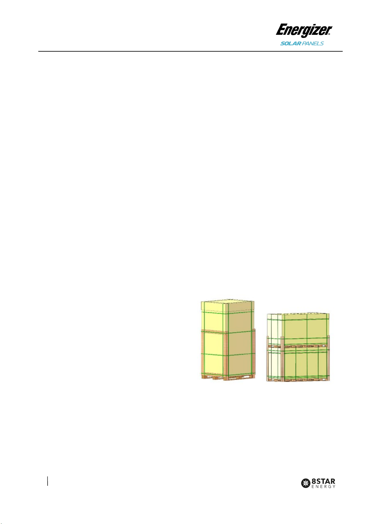
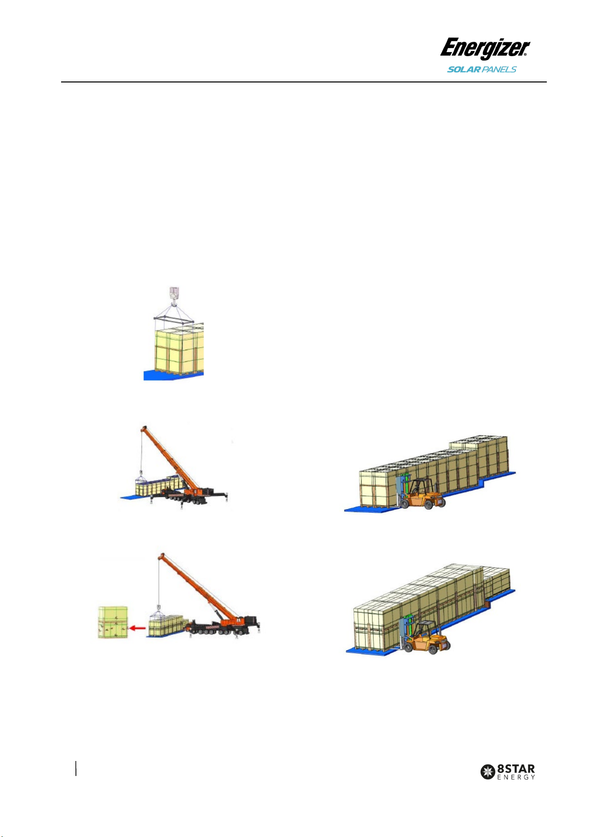
must be cardboard bedding under the photovoltaic
modules. For example, when installing photovoltaic
modules on the roof, the number of modules stacked
up on a pile should not exceed 20. For roofs with
poor load-bearing capacity, it is recommended that
the designer or installer evaluate the load-bearing
capacity of the roof and reduce the load-bearing unit
area of the roof by reducing the number of piles. At
the same time, avoid placing any installation tools or
other objects on the surface of the photovoltaic
module.
Energizer Solar PV modules adopt high and low
current bins, and the handlers need to place them
separately and mark them according to the markings
on the power list of the PV modules outer packaging
(for example, 270W-L means low current gear;
270W-H means high current gear position; the
current division method required by other customers
is similar). According to the system design
requirements, the same current gear position is
usually required in the same array during installation.
If the customer requires PV modules to be
distinguished by color, the outer packaging box shall
be marked accordingly, and the PV modules shall be
marked to prevent confusion when they are taken
out of the packaging box and stacked. According to
the system design requirements, the color of
photovoltaic modules in the same row or square
array should be the same.
6 Mechanical installation
6.1 Installation conditions
•Recommended ambient temperature: -20°C to
+50°C;
•Extreme working environment temperature of
photovoltaic modules: -40°C to +85°C.
•Photovoltaic modules mechanical load: Under
standard installation conditions, the maximum
test snow/wind load is 5400Pa/2400Pa, and the
design load (considering a safety factor of 1.5)
is 3600Pa/1600Pa.
For specific installation methods and mechanical
load values of photovoltaic modules, please refer to
Table 2 for detailed installation instructions for
photovoltaic modules.
Photovoltaic modules are strictly prohibited to be
installed and used in excessive environments such
as hail, snow, hurricane, sandstorm, dust, air
pollution, and soot. It is strictly forbidden to install or
use photovoltaic modules in an environment with
strong corrosive substances (such as salt, salt spray,
salt water, active chemical vapor, acid rain, strong
steam, or any other substances that will corrode
photovoltaic modules and affect the safety or
performance of photovoltaic modules).
If photovoltaic modules will be installed in special
environments such as high temperature and high
humidity environment, wet salt fog environment (C3
and above areas specified in ISO 9223), water and
breeding farms, etc., the purchaser or user must
inform 8 Star Energy in advance. The types of
photovoltaic modules, BOM, and quality assurance
issues shall be decided by the two parties through a
joint agreement and understanding.
If the above precautions are not followed, the
warranty will be invalid.
6.2 Installation angle selection
•The tilt angle of the modules is measured
between the surface of modules and a
horizontal grounding face, as shown in figure 1.
The modules generate maximum power output
when it faces the sun directly.
•In the northern hemisphere, modules should
typically face south, and in the southern
hemisphere, modules should typically face
north. Dust building up on the surface of the
modules can impair module performance, 8
Star Energy recommends installing the modules
with a tilt angle of at least 10 degrees, making it
easier for dust to be washed off by rain. At the
same time, it is conducive to the flow of
accumulated water on the surface of the

11
8 Star Energy Pty Ltd | Level 35, 477 Collins Street, Melbourne VIC 3000 | https://www.energizersolar.com
8 Star Energy ESS Ltd | The Black Church, St Mary’s Place, Dublin DO7 P4AX, Ireland
module, and avoids long-term large amounts of
accumulated water leaving marks on the glass
surface, thereby affecting the appearance and
performance of the module.
Figure 1: Schematic diagram of tilt
angle
•PV modules connected in series should be
installed in the same orientation and angle. If
the orientation and angle are different, the solar
radiation received by each module may be
different, resulting in power loss.
6.3 Installation Method
•The photovoltaic module mounting bracket
must be made of durable, corrosion-resistant,
and UV-resistant materials. The mounting
bracket must be inspected and tested by a
third-party testing organization with static
mechanical analysis capabilities to meet the
country, region, or corresponding international
standards.
•The photovoltaic module must be firmly fixed on
the mounting bracket. If the photovoltaic
module is installed in a snow-covered area, the
height of the support should ensure that the
lowest point of the photovoltaic module will not
be covered by snow. In addition, it should be
ensured that the lowest point of the photovoltaic
module will not be blocked by surrounding trees
or other plants.
•When the photovoltaic module is installed on a
bracket parallel to the roof, the minimum gap
between the frame of the photovoltaic module
and the roof is 10cm, and air circulation is
required to prevent damage to the wiring of the
photovoltaic module.
•The frame of the photovoltaic module will have
the effect of thermal expansion and contraction,
and the spacing between the two adjacent
photovoltaic module frames should not be less
than 10mm during installation.
For specific installation methods, please refer to the
following installation specifications.
6.4 Bolting through the mounting holes
All modules must be securely fastened with at least
4 bolts (As shown in Figure 2, 3, 4, 5, 6, 7, 8, 9).
Figure 2: Bolt installation for 54 cell
Figure 3: Bolt installation for 60 cell
Figure 4: Bolt installation for 66 cell

12
8 Star Energy Pty Ltd | Level 35, 477 Collins Street, Melbourne VIC 3000 | https://www.energizersolar.com
8 Star Energy ESS Ltd | The Black Church, St Mary’s Place, Dublin DO7 P4AX, Ireland
Figure 5: Outer four-hole bolt installation
for 72cell
Figure 6: Internal four-hole bolt installation for 72cell
Figure 7: 400mm spacing bolt installation
for 60 cell
Figure 8: 400mm spacing bolt installation
for 66 cell
Figure 9: 400mm spacing bolt installation
for 72 cell
In order to achieve maximum safety
precautions against wind and snow
loads, it is recommended that all
available mounting holes should be
used.
Bolts are inserted as described in the process below.
Figure 10: Schematic diagram of bolt
installation process
①Place the module on the supporting bars
underneath.
②Insert the four stainless-steel bolts (M6) through
the holes (7x11.5mm) or stainless-steel bolts
(M8) through the holes (9x14mm) in the frame
according to the Figure 2, 3, 4, 5, 6, 7, 8, 9. The
400mm spacing bolt hole size is 7x10mm, and 4

13
8 Star Energy Pty Ltd | Level 35, 477 Collins Street, Melbourne VIC 3000 | https://www.energizersolar.com
8 Star Energy ESS Ltd | The Black Church, St Mary’s Place, Dublin DO7 P4AX, Ireland
x M6 stainless steel bolts are required (Figure
5).
③Secure each bolt to the frame with
stainless-steel washers, one for each side of the
mounting structure; and screw on either a
stainless-steel spring washer or a toothed lock
washer. Finally, secure with a stainless steel nut.
④The reference value of tightening torques should
be within 9~12Nm & 17~23 Nm respectively for
M6 & M8 bolts, depending on bolt class. For the
bolt grade, the technical guideline from the
fastener suppliers should be followed. For the
torque value, recommendations from specific
clamping hardware suppliers should prevail.
6.5 Clamping on the frame surface
Photovoltaic modules can be installed across the
support frame (Figure 11) or parallel to the frame of
the photovoltaic module (Figure 12). When using
clamps to install, each photovoltaic module must be
fixed with at least 4 clamps.
Figure 11: Rail vertical long frame
installation
Figure 12: Rails overlapping for the
short-side of frame
Figure 13: Four clamp mounting on short
side of frame.
The length of supporting bars must be
longer than the length of module frame,
otherwise please confirm with our
product team to get approval.
•The above three diagrams show the installation
method using aluminum clamps (also called
fixtures). "D" indicates the allowable installation
range of the aluminum press block. Please refer
to Table 2 for the specific recommended
installation location and corresponding load
("---" indicates that the photovoltaic module
does not apply to the above installation
methods).
•Each aluminum pressure block is equipped with
an M8 bolt, a flat washer, a spring washer and
an M8 nut. The fixing steps are as follows:
①Place the module on the two supporting bars (not
provided). The bars should be made with
stainless material and treated with an
anti-corrosion process (e.g., hot dipped
galvanizing). Each PV module needs at least four
clamps to fix. Do not make the clamp have
contact with the glass directly and do not make
the aluminum frame distort as part of the
installation process. Avoid shadowing of the solar
PV modules, otherwise this may affect the
modules operation or performance.
②Be sure to avoid shadowing effects from the
module clamps. Weep holes on the module frame
must not be closed or obscured by the clamps.

14
8 Star Energy Pty Ltd | Level 35, 477 Collins Street, Melbourne VIC 3000 | https://www.energizersolar.com
8 Star Energy ESS Ltd | The Black Church, St Mary’s Place, Dublin DO7 P4AX, Ireland
The clamp must overlap the module frame by at
least 8mm but no more than 11mm (The clamp
section can be changed under the premise of
ensuring the reliable installation of the
components).
③The bar’s top surface contacted with module
frame should come with grooves compatible with
an M8 bolt.
④If the bars do not come with grooves, holes of a
suitable diameter may need to be drilled to allow
bolts to be attached to the bars at the same
locations as mentioned above.
⑤Secure each clamp by attaching plain washer,
spring washer, and nut, in that order.
⑥Both close-ups in Figure 10, indicating the middle
clamps and Figure 9, indicating the side clamps
are for reference. Suggested dimensions for
middle clamps are: a ≥40 mm, b ≥26 mm, c≥
5 mm, d ≥28 mm, and Ø = 9 mm. The torque for
tightening the nut and bolts are recommended
17~23Nm when the property class of bolts and
screws is Class 8.8.
Figure 14: Schematic diagram of
intermediate pressing block
⑦For the installation method shown in Figure 8, the
modules need to be fixed with professional solar
pressure blocks (as shown in Figure 11), and the
overlap between the C surface of the module and
the guide rail should be ≥15mm. If improper
fixtures or incorrect installation methods are used,
the limited warranty will be invalid.
Figure 13: Schematic diagram of side
pressing block
Figure 14: Requirements for mounting
clamps when the guide rails coincide with
the long frame, overlap with the short
sided frame

15
8 Star Energy Pty Ltd | Level 35, 477 Collins Street, Melbourne VIC 3000 | https://www.energizersolar.com
8 Star Energy ESS Ltd | The Black Church, St Mary’s Place, Dublin DO7 P4AX, Ireland
Table 2 Installation range and corresponding values
Module type Dimensions
L*W*H (mm)
Installation method
Figure
2, 3, 4, 5
Fig 6 Fig 11 Fig 12 Fig 13 Fig 7,8,9
ENSP54M2
ENSP54M2BL
ENSP54N2
ENSP54NBL2
1708*1133*30
1708*1133*35
+5400Pa
-2400Pa ---
+5400/-2400Pa
Installation
scope
309~409mm
+1800/-1800Pa
Installation
scope
150~250mm
+1800/-1800Pa
Installation
scope
0~250mm
---
1722*1134*30
1722*1134*35
+5400Pa
-2400Pa ---
+5400/-2400Pa
Installation
scope
316~416mm
+1800/-1800Pa
Installation
scope
150~250mm
+1800/-1800Pa
Installation
scope
0~250mm
---
ENSP60M1
ENSP60M2
ENSP60NBL2
1755*1038*30
1765*1048*35
+5400Pa
-2400Pa ---
+5400/-2400Pa
Installation
scope
400±50mm
+1800/-1800Pa
Installation
scope
200±50mm
--- ---
1755*1038*30 +5400Pa
-2400Pa ---
+5400/-2400Pa
Installation
scope
350~400mm
--- --- ---
1903*1134*30 +5400Pa
-2400Pa
+5400Pa
-2400Pa
+5400/-2400Pa
Installation
scope
320~520mm
+1600/-1600Pa
Installation
scope
150~250mm
--- ---
2172*1303*35 +5400Pa
-2400Pa ---
+5400/-2400Pa
Installation
scope
375~425mm
--- ---
+1800Pa
-1800Pa
+Bumper
ENSP72M1
ENSP72M2
ENSP72N2
2094*1038*35 +5400Pa
-2400Pa
+2400Pa
-2400Pa
+5400/-2400Pa
Installation
scope
400±50mm
--- ---
+2400Pa
-2400Pa
+Bumper
2094*1038*30 +5400Pa
-2400Pa ---
+5400/-2400Pa
Installation
scope
400~450mm
--- --- ---
2256*1133*35 +5400Pa
-2400Pa
+2400Pa
-2400Pa
+5400/-2400Pa
Installation
scope
400~500mm
--- ---
+1800Pa
-1800Pa
+Bumper
2278*1134*35 +5400Pa
-2400Pa ---
+5400/-2400Pa
Installation
scope
400~500mm
--- ---
+1800Pa
-1800Pa
+Bumper
2278*1134*35 +5400Pa
-2400Pa ---
+5400/-2400Pa
Installation
scope
430~530mm
--- --- +1800Pa
-1800Pa
7 Electrical Installation
7.1 Installation Conditions
Module electrical ratings are measured under
Standard Test Conditions (STC: 1000W/m2
irradiance, AM1.5 spectrum and a cell temperature
of 25°C). Please refer to the datasheet or the
product nameplate for the main electrical
characteristics, maximum system voltage and
tolerance of Isc, Voc and Pmpp.
Under certain conditions, the output current
and/or voltage of the PV module may be higher
than the value under standard testing conditions.
Therefore, the value of Isc marked on the module
should be multiplied by 1.25, and Voc on the
module should be multiplied by a correction factor
(see table 3 below) when determining component

16
8 Star Energy Pty Ltd | Level 35, 477 Collins Street, Melbourne VIC 3000 | https://www.energizersolar.com
8 Star Energy ESS Ltd | The Black Church, St Mary’s Place, Dublin DO7 P4AX, Ireland
ratings and capacities. Depending on your local
regulations, an additional 1.25 multiplier forthe
Isc(giving a total multiplier of 1.56) may be
applicable when sizing conductors and fuses.
Table 3 Correction factor of Voc at low temperature
Lowest Estimated
Ambient
Temperature(℃)
Correction
factor
24 ~20 1.02
19 ~15 1.04
14 ~10 1.06
9 ~5
1.08
4~0 1.10
-1 ~-5 1.12
-6 ~-10 1.14
-11 ~-15 1.16
-16 ~-20
1.18
-21 ~-25 1.20
-26 ~-30 1.21
-31 ~-35 1.23
-36 ~-40 1.25
Alternatively, a more accurate correction factor for
the Voc can be calculated using the following
formula:
C
voc=1-αVoc x(25-Tmin)
Where:
C
voc is the correction factor of Voc.αVoc
(%/°C) is the open-circuit voltage temperature
coefficient of the selected module (refer to
corresponding datasheet).Tmin(°C) is the expected
lowest ambient temperature at the system
installation site.
The string voltage must not be higher than the
maximum system voltage, as well as the maximum
input voltage of the inverter and other electrical
equipment installed in the system. To ensure the
above requirements, the open-circuit voltage of
the string needsto be calculated using the
following formula:
Maximum system voltage≥N*
V
oc*Cvoc
Where: N is the number of PV modules in a single
string. Vocis the open-circuit voltage of each PV
module (refer to the nameplate or product
datasheet).
Depending on the maximum fuse
ratings of the PV module, and the
local electrical installation
standards, the connection of
parallel strings of PV modules needs to be
equipped with suitable fuses or preventive diodes
for circuit protection purposes. Electrical
calculations and design must be performed by a
competent engineer or consultant.
The IEC & UL standard maximum system voltage for
the regular module series is 1500V according to the
requirements. The IEC & UL standard maximum
system voltage for half-cell module series is 1500V.
The maximum voltage of the system must be less
than the maximum certified voltage and the
maximum input voltage of the inverter and of the
other electrical devices installed in the system.
To calculate the maximum number of connections of
a series of PV modules, the following formula can be
used:
N = 1500V / (VOC * (1+(Tmin-25℃) * x%)
which shall consider the lowest on-site temperature.
In the formula,1500V is the system voltage, VOC is

17
8 Star Energy Pty Ltd | Level 35, 477 Collins Street, Melbourne VIC 3000 | https://www.energizersolar.com
8 Star Energy ESS Ltd | The Black Church, St Mary’s Place, Dublin DO7 P4AX, Ireland
the corresponding open-circuit voltage of the module
under STC condition, and Tmin(°C) is the lowest
on-site temperature. 25 ℃is the standard cell
temperature, and x% is the temperature coefficient
corresponding to the open-circuit voltage from the
panel spec sheet.
When the modules connect in parallel, the output
current will be equal to the sum of each branch
current. We suggest that every series SPV module
string should be fused prior to be connected with
other strings. The maximum number of modules:
N = Imax (maximum fuse current)/Isc.
Please refer to the applicable regional and local
codes for additional fuse requirements.
Under normal conditions, a photovoltaic
module is likely to experience conditions
that produce more current and/or voltage
than reported at standard test conditions.
Accordingly, the value of Isc marked on this
module should be multiplied by a factor of 1.25
when determining component conductor
ampacities, fuse sizes, and size of controls
connected to the PV output.
•Refer to Section 690-8 of the National Electrical
Code for an additional multiplying factor of
125% (80% derating)which may be applicable.
That means, when determining the voltage
rating, conductor capacity, fuse rating, and
photovoltaic output control size, the parameters
need to be multiplied by the square of 1.25.
•According to the max fusing rate of modules
and local electical installation standard, the
parallel connection of PV module arrays should
use the proper fuse to protect the circuit.
7.2 Installation conditions
In order to ensure the normal operation of the
system, when connecting photovoltaic modules or
connecting loads (such as inverters, batteries, etc.),
observe to ensure that the polarity of the cable is
connected correctly. If the PV module is not
connected correctly, the bypass diode may be
damaged. Figure 12 shows the connection of
photovoltaic modules in series and parallel. PV
photovoltaic modules can be wired in series to
increase the voltage. The series connection is to
connect the wiring from the positive terminal of one
photovoltaic module to the negative terminal of the
next photovoltaic module. PV photovoltaic modules
can be connected in parallel to increase current.
Parallel connection is to connect the wiring from the
positive terminal of one photovoltaic module to the
positive terminal of the next photovoltaic module. If
the PV module is not connected correctly, the
bypass diode may be damaged.
Figure 17 Schematic diagram
of electrical connection

18
8 Star Energy Pty Ltd | Level 35, 477 Collins Street, Melbourne VIC 3000 | https://www.energizersolar.com
8 Star Energy ESS Ltd | The Black Church, St Mary’s Place, Dublin DO7 P4AX, Ireland
•If one set of arrays is connected to
another with the opposite polarity,
it will cause irreparable damage to
the product. Before connecting in parallel, be
sure to confirm the voltage and polarity of each
column. If the measurement finds that the polarity
between the columns is reversed or the voltage
difference is greater than 10V, you must check
the structure and configuration before making the
connection.
•The number of photovoltaic modules in series
and parallel must be designed reasonably
according to the system configuration.
•Photovoltaic modules of different electrical
performance models cannot be connected in a
string.
•Special solar cables and connectors should be
used in the system, and all connections should
be securely tightened. The cable size should be
4mm2 (12 AWG) and must be able to withstand
the maximum open circuit voltage of the
photovoltaic system.
•When the cable is fixed on the bracket, it is
necessary to avoid mechanical damage to the
cable or photovoltaic module, and do not press
the cable with force. To fix the cable through the
proper way, a specially designed tying coil and
wire clip must be used to fix it on the bracket.
Avoid direct sunlight and water soaking cables.
•Please keep the connector dry and clean, and
make sure that the nut of the connector is
tightened before connecting. Do not connect the
connector when it is found that the connector is
wet, dirty, or in other bad conditions. Avoid direct
sunlight and immersion of the connector in water.
Avoid the connector falling on the ground or roof.
•When the photovoltaic module is in a live state,
please do not plug or unplug the connector.
When it is necessary to open the connector,
ensure that the photovoltaic module is in a
non-working state, and must use professional
unlocking tools and safety protection measures. It
is forbidden to pull or damage the locking
structure.
•The junction box of the photovoltaic module
contains bypass diodes connected in parallel to
the battery string of the photovoltaic module. The
bypass diode in the junction box can avoid the
degradation of photovoltaic module performance
caused by shading or covering. Please refer to
the junction box diode specifications provided in
the relevant product specifications.
•When a local hot spot phenomenon occurs due to
partial shading or covering of the photovoltaic
module, the diode in the junction box will start to
work, so that the photovoltaic module current will
no longer flow through the hot spot cell, thereby
limiting the heating and performance loss of the
photovoltaic module. When you suspect or find
that the diode is malfunctioning, please contact 8
Star Energy, please do not try to open the
junction box cover by yourself.
7.3 Grounding
Energizer Solar modules use an anodic oxidized
aluminum frame to resist corrosion. So the frame of
modules should be connected to the equipment
grounding conductor to prevent electrical shock. The
grounding device should fully make contact with the
inside of the aluminum alloy, and penetrate the
surface of the frame oxidation film.
The following is the specific grounding method, as
shown in Figure 13.

19
8 Star Energy Pty Ltd | Level 35, 477 Collins Street, Melbourne VIC 3000 | https://www.energizersolar.com
8 Star Energy ESS Ltd | The Black Church, St Mary’s Place, Dublin DO7 P4AX, Ireland
Figure 18 Use copper cables to ground
the aluminum frame
•The grounding requirements must be
checked in accordance with the applicable
regulations and standards before work is
started.
•Use the marked 5.5 mm grounding holes to
ground the anodized frame. Use one M5 nut,
two M5 cut washers, one M5 plain washer,
one M5 spring washer, and one M5 bolt and
the copper wire. All nuts, bolts, and washers
are type M5 and should be made of stainless
steel.
•Put the bolt through the cup washer and
wrap the copper wire around the bolt. (Note
that the copper wire cannot be attached
directly to the aluminum.)
•Put the bolt through the cut washer and then
through the hole in the aluminum frame.
•Add the spring washer and nut on the other
side of the bolt and tighten to secure all parts.
The tightening torque should be 4~4.5 N•m.
Approve the use of UL-467
certified bonding and grounding
devices, including Burndy
(formerly Wiley Electronics) Washer
Electrical Equipment Bonding (WEEB) and
similar devices, such as barbed washers,
that meet the requirements of UL-467 as
suitable for electrical bonding and grounding
PV modules to PV mounting systems.
•Other grounding methods may be allowable
when tested with the racking system per UL
2703 requirements.
•Please don’t drill any additional grounding
hole on the frame of the modules.
•The frame rails have pre-drilled holes
marked with a grounding sign. These holes
should be used for grounding purposes and
should not be used for mounting the
modules.
8 Maintenance
It is required to perform regular inspection and
maintenance of the modules, especially within
warranty scope. It is the user’s responsibility to the
report to the supplier regarding the damages found
in time.
8.1 Routine inspection
Regular inspections should be made to see if the
photovoltaic modules in the photovoltaic array are
damaged, such as glass breakage, cable breakage,
junction box damage, cell damage, backplane
breakage and other factors that lead to functional
and safety failures of photovoltaic modules. When
the above problems occur, the supplier must be
notified in time to replace the same type of
photovoltaic modules.
It is recommended to perform a preventive
inspection every 6 months, and do not replace the
components of the photovoltaic module without
authorization. If electrical or mechanical
performance inspection or maintenance is required,
it is recommended that qualified professionals
perform the operation to avoid electric shock or
personal injury.
Routine maintenance measures should be taken to
keep the photovoltaic modules free of snow, bird
droppings, seeds, pollen, leaves, branches, dust,
stains, etc.

20
8 Star Energy Pty Ltd | Level 35, 477 Collins Street, Melbourne VIC 3000 | https://www.energizersolar.com
8 Star Energy ESS Ltd | The Black Church, St Mary’s Place, Dublin DO7 P4AX, Ireland
8.2 Photovoltaic module cleaning
If the PV module has a sufficient tilt angle (at least
15°), it is usually not necessary to clean the PV
module (rain will have a self-cleaning effect). If there
is a lot of dirt on the surface of the photovoltaic
module, which has seriously affected the power
generation, use water without detergent and a soft
sponge or brush to rinse the photovoltaic module
array when it is cool throughout the day. Do not
scratch or wipe the dust when it is dry, otherwise it
will cause tiny scratches. If there is snow, you can
use a brush with soft bristles to clean the surface of
the photovoltaic module.
For more detailed instructions related to cleaning
and maintenance, please refer to the "Photovoltaic
Module Cleaning Manual".
Modified version and date
· Rev1.4, released in April 2023.
8 Star Energy Pty Ltd
Level 35, 477 Collins St,
Melbourne VIC 3000, Australia
8 Star Energy ESS Ltd
The Black Church, St Mary’s Place,
Dublin DO7 P4AX, Ireland
Support Email Address: hello@energizersolar.com
Support Number: +61 1300 757 827
© 2023 Energizer. Energizer and certain graphic designs are trademarks of Energizer Brands, LLC and related subsidiaries and are used
under license by 8 Star Energy Pty Ltd. All other brand names are trademarks of their respective owners. Neither 8 Star Energy Pty Ltd nor
Energizer Brands is affiliated with the respective owners of their trademarks.
Other manuals for Beam Series
1
This manual suits for next models
17
Table of contents
Other Energizer Inverter manuals

Energizer
Energizer eZV3200 User manual

Energizer
Energizer EZG Series User manual

Energizer
Energizer EN1100 User manual

Energizer
Energizer SOLAR Force Series User manual

Energizer
Energizer FORCE Series User guide

Energizer
Energizer ENK1100 User manual

Energizer
Energizer EZG1300 User manual

Energizer
Energizer FORCE S Series User guide

Energizer
Energizer eZV 4500W i-Series User manual

Energizer
Energizer ENA548 User manual