infobit Dante iSound 44D User manual
INFOBIT AV www.infobitav.com [email protected]
1
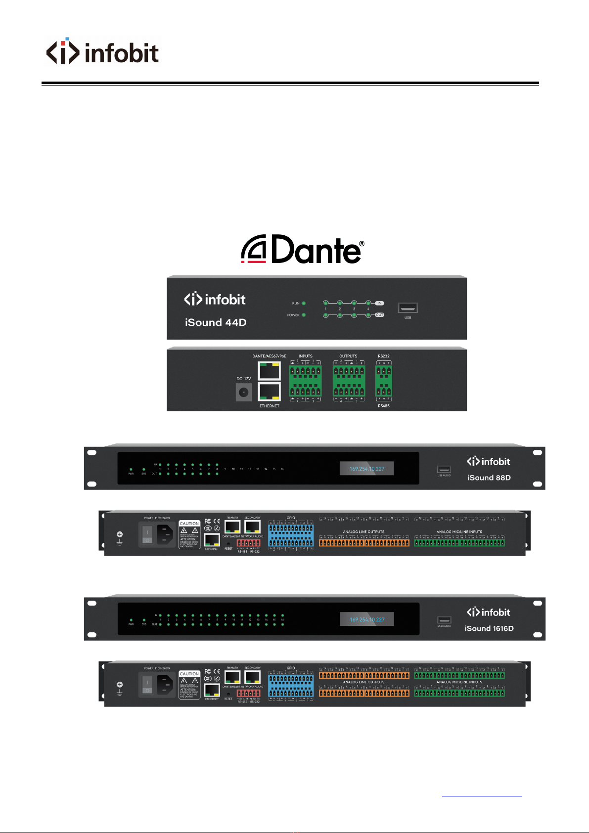
iSound 44D/88D/1616D
4x4, 8x8 and 16x16 Digital Sound Processor w/ Dante
User Manual V2.0

INFOBIT AV www.infobitav.com [email protected]
2
1. Technology .................................................................................. 6
1.1 Introduction ..................................................................................................................................... 6
1.2 Audio Input Section ......................................................................................................................... 6
1.3 Audio Output Section ...................................................................................................................... 7
1.4 Float Point DSP ................................................................................................................................ 7
1.5 Audio Flow ....................................................................................................................................... 9
2. Hardware ................................................................................... 10
2.1 Safety Instructions ......................................................................................................................... 10
2.2 Audio Wiring Reference ................................................................................................................. 11
2.3 Specifications ................................................................................................................................. 12
2.4 Mechanical Data ............................................................................................................................ 13
2.5 Front Panel .................................................................................................................................... 13
2.5.1 iSound 44D Front Panel .......................................................................................................... 13
2.5.2 iSound 88D/1616D Front Panel .............................................................................................. 14
2.6 Rear Panel ...................................................................................................................................... 15
2.6.1 iSound 44D Rear Panel ............................................................................................................ 15
2.6.2 iSound 88D/1616D Rear Panel ................................................................................................ 16
3. Software .................................................................................... 18
3.1 Software Installation ...................................................................................................................... 18
3.2 Using the Software ........................................................................................................................ 19
3.3 Custom edit processing module .................................................................................................... 19
3.4 Audio Module Parameters ............................................................................................................. 20
3.4.1 Input Source ............................................................................................................................ 21
3.4.2 Expander ................................................................................................................................. 22
3.4.3 Compressor & Limiter ............................................................................................................. 23
3.4.4 Auto Gain Control ................................................................................................................... 25
3.4.5 Equalizers ................................................................................................................................ 26
3.4.6 Figure Balancer ....................................................................................................................... 27

INFOBIT AV www.infobitav.com [email protected]
3
3.4.7 Feedback Inhibition ................................................................................................................. 28
3.4.8 Noise Gate ............................................................................................................................... 30
3.4.9 Ducker ..................................................................................................................................... 31
3.4.10 Spl ......................................................................................................................................... 32
3.4.11 AutoMixer ............................................................................................................................. 33
3.4.12 Acoustic Echo Cancellation ................................................................................................... 36
3.4.13 Noise Suppression ................................................................................................................. 36
3.4.14 Matrix .................................................................................................................................... 37
3.4.15 High & Low Pass Filter ........................................................................................................... 37
3.4.16 Delay ..................................................................................................................................... 38
3.4.17 Output ................................................................................................................................... 38
3.4.18 Camera Tracking ................................................................................................................... 39
3.4.19 USB Soundcard ...................................................................................................................... 41
3.5 Setting Menu ................................................................................................................................. 42
3.5.1 File Menu ................................................................................................................................ 42
3.5.2 Device Setting ......................................................................................................................... 42
3.5.3 GPIO Setting ............................................................................................................................ 43
3.5.4 Group Setting .......................................................................................................................... 45
3.5.5 Panel Setting ........................................................................................................................... 46
3.5.6 User Interface ......................................................................................................................... 49
3.5.7 Mobile Device ......................................................................................................................... 50
3.5.8 Dante Setting .......................................................................................................................... 52
3.5.9 Help Menu .............................................................................................................................. 56
4. Dante Audio .............................................................................. 57
4.1 Dante Overview ............................................................................................................................. 57
4.2 Dante Requirements ...................................................................................................................... 58
4.3 Dante Network Design ................................................................................................................... 58
4.4 Dante Modes ................................................................................................................................. 60
4.5 Dante Controller ............................................................................................................................ 61
4.6 Dante Virtual Soundcard ............................................................................................................... 61

INFOBIT AV www.infobitav.com [email protected]
4
5. Control ....................................................................................... 62
5.1 Protocol format ............................................................................................................................. 62
5.1.1 0x21: parameter control ......................................................................................................... 63
5.1.2 0x22: obtain parameter. ......................................................................................................... 63
5.1.3 0x13: Switch presets ............................................................................................................... 63
5.1.4 0x74: Other control ................................................................................................................. 63
5.2 Dante Routing (0x6e) ..................................................................................................................... 65
5.3 Serial Port-to-UDP (RS232 To UDP) ............................................................................................... 65
5.4 ASCII Control Commands ............................................................................................................... 66
5.4.1 Input volume control and acquisition ..................................................................................... 66
5.4.2 Output volume control and acquisition .................................................................................. 66
5.4.3 Phantom power supply control and acquisition ..................................................................... 67
5.4.4 Input Mute Control and Acquisition ....................................................................................... 67
5.4.5 Output mute control and acquisition ...................................................................................... 67
5.4.6 Control and acquisition of sensitivity ...................................................................................... 67
5.4.7 Control acquisition of matrices ............................................................................................... 67
5.4.8 Invocation and Saving of Scenarios ......................................................................................... 67
5.4.9 Input level acquisition ............................................................................................................. 68
5.4.10 Output level acquisition ........................................................................................................ 68
5.4.11 System Mute Control and Acquisition .................................................................................. 68
5.4.12 Settings and getting the channel name of the input and output .......................................... 68
5.4.13 Input and output inverting control and acquisition .............................................................. 68
5.4.14 Input and output step control and acquisition ..................................................................... 68
5.4.15 Input and output link control and acquisition ...................................................................... 68
5.4.16 Control and acquisition of signal generators ........................................................................ 69
5.4.17 Restore factory settings control ............................................................................................ 69
5.4.18 Scene Reset Control .............................................................................................................. 69
5.4.19 Get the name of the scene that is set arbitrarily .................................................................. 69
5.4.20 Module name:input,output|mixer ....................................................................................... 69
5.4.21 Format the instruction: ......................................................................................................... 70

INFOBIT AV www.infobitav.com [email protected]
5
5.4.22 Get the instruction format .................................................................................................... 70
6. FAQs ........................................................................................... 70
1. How to restore factory setting? ....................................................................................................... 70
Appendix A: Module ID Distribution .................................................................................................... 71
Appendix B: Module Parameter Types (1) ........................................................................................... 72
Appendix B: Module Parameter Types (2) ........................................................................................... 73
This manual suits for next models
2
Table of contents
Other infobit Recording Equipment manuals


