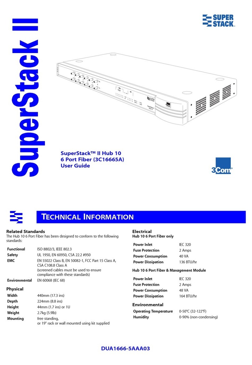
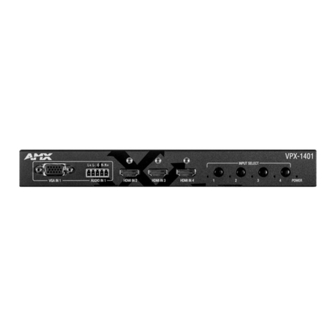
infobit iShare+ User manual

1
iShare+
4 x 2 Presentation Switcher with local sources and BYOD
Version: V2020.01
User Manual

2
Important Safety Information
1. Read, follow, and keep these instructions.
2. Heed all warnings.
3. Do not use this product near water. Keep away from wet places, such as: spas, pools, sinks,
laundries, wet basements, etc.
4. When cleaning, unplug the switcher and wipe with a dry cloth. Do not use damp cloths, cleaning
fluids, or aerosols which may result in electric shock, fire, or switcher damage.
5. Operate this product using only the included power supply and/or power cable. Use of an
unapproved power implement may impair performance, damage the product, or cause fires.
6. Do not block any ventilation openings. Install in accordance with the manufacturer’s instructions.
7. Do not install or place this product near any heat sources such as radiators, heat registers, stoves,
or other apparatus (including amplifiers) that produce heat.
8. Protect the power cord from being walked on or pinched particularly at plugs, convenience
receptacles, and the point where they exit from the product.
9. Only use attachments/accessories specified by BC to avoid fire, shock, or other hazards.
10. To reduce the risk of electric shock and/or damage to this product, never handle or touch this
switcher or power cord if your hands are wet or damp. Do not expose this product to rain or
moisture.
11. Unplug this product during lightning storms or when unused for long periods of time.
12. Never open, remove switcher panels, or make any adjustments not described in this manual.
Attempting to do so could result in electric shock, damage to the switcher, or other hazards.

3
Contents
Important Safety Information..........................................................................................................................................2
1. Introduction................................................................................................................................................................. 1
2. Features........................................................................................................................................................................ 1
3. Package Contents..................................................................................................................................................... 1
4. Panel Description.......................................................................................................................................................1
Front Panel.................................................................................................................................................................1
Rear Panel..................................................................................................................................................................3
5. Specifications..............................................................................................................................................................4
6. Installation and Wiring..............................................................................................................................................5
Installation..................................................................................................................................................................5
Wiring..........................................................................................................................................................................5
7. Key Function................................................................................................................................................................6
Screen Layout Switch..............................................................................................................................................6
Automatic Signal Switching....................................................................................................................................7
Screen Mirroring....................................................................................................................................................... 7
(1) Screen Mirroring over Airplay........................................................................................................................... 7
(2) Screen Mirroring over Miracast........................................................................................................................ 8
(3) Screen Mirroring over USB Dongle............................................................................................................... 11
Guide Screen.......................................................................................................................................................... 12
OSD...........................................................................................................................................................................12
8. Web UI.........................................................................................................................................................................14
General Tab............................................................................................................................................................. 15
Device Name...........................................................................................................................................................15
Network....................................................................................................................................................................15
Access Code...........................................................................................................................................................16
Analog Audio Latency........................................................................................................................................... 16
Soft AP Password.................................................................................................................................................. 16
Output.......................................................................................................................................................................17
Sink Power Management......................................................................................................................................17
Password................................................................................................................................................................. 18
Guide Screen Picture.............................................................................................................................................19
Maintenance............................................................................................................................................................19
Version Information................................................................................................................................................19
Video Source Tab...................................................................................................................................................20
State & Switch.........................................................................................................................................................20
Manage Alias...........................................................................................................................................................20
9. Video Source Tab.....................................................................................................................................................21

1
1. Introduction
The iShare Plus is a high-performance BYOD presentation switcher with wireless presentation capability.
It equips the built-in Wi-Fi module and supports multiple access approaches, including Airplay Mirroring,
Miracast, physical interfaces (HDMI, VGA and USB-C) and USB Dongle, with which you can project
screen contents of your computer (Mac/Windows) or mobile device (iPhone/iPad/Android) to a display in
Multiview mode.
Multiple features like fast seamless switching, auto signal switch, serial control, CEC, Guide Screen, OSD
display, USB switching and extension are included. The switcher is a collaboration terminal used for your
meeting room.
2. Features
Multiview presentation with configurable screen layout.
Built-in Wi-Fi module for wireless connectivity with devices over Airplay, Miracast and USB Dongle.
Fast seamless switching for both single view and Multiview.
Supports HDMI input resolutions up to 4K@30Hz 4:4:4.
Supports HDMI output resolutions up to 4K@60Hz 4:4:4.
Detailed and friendly OSD information.
Supports USB extension and switching control among three USB hosts.
Offers multiple control approaches: front panel buttons, Web UI and Telnet API.
Multiview layout adjustable by the end user.
3. Package Contents
1 x Switcher
1 x DC 12V Power Adapter (with US, UK, EU, AU pins)
2 x Phoenix Male Connectors (3.5 mm, 4 Pins)
2 x Mounting Brackets (with Screws)
2 x Wi-Fi Antennas
4. Panel Description
Front Panel

2
No.
Name
Description
1
Power LED
On: The switcher is powered on.
Off: The switcher is powered off.
2
Status LED
On: The switcher is outputting at least one video source.
Blinking: The switcher is in standby mode.
Off: The switcher is outputting Guide Screen.
3
Source Switch
VGA IN ~ USB-C IN Buttons:
Short press to output or stop outputting the corresponding video source.
Hold press to output the corresponding video source in full screen mode.
VGA IN ~ USB-C IN LEDs:
On: The corresponding video signal is valid and is being output.
Blinking quickly: The corresponding video signal is valid but is not being output.
Blinking slowly: The corresponding video signal is being output but is not valid.
Off: The switcher is in standby mode. / The corresponding video signal is neither valid nor
being output.
4
HDMI 2 Output
HDMI2 Output button: press to switch between Follow mode and Matrix mode for HDMI Output
2.
To switch to Follow mode: long press the HDMI2 Output button until the Follow LED lights
up. In Follow mode, HDMI OUT 2 follows HDMI OUT 1 to output the same video content as
that of HDMI OUT 1.
To switch to Matrix mode: short press the HDMI 2 Output button. In Matrix mode, HDMI
OUT 2 will output a specific video source in single view (specified by Telnet API or Web UI);
continue to short press the button, the HDMI OUT 2 will cycle through the hardware video
sources (VGA > HDMI 1 > HDMI 2 > USB-C > VGA >…) for output.
LED Status:
Follow LED: Lights up when Follow mode is selected.
Matrix LED: Lights up when Matrix mode is selected.
5
USB
Connect to a U-disk for firmware upgrade.
Connect to the USB Dongle for pairing up with each other.
6
Reset
Hold press this button for five or more seconds and then release, it will automatically reboot and
restore to its factory defaults.

3
Rear Panel
No.
Name
Description
1
Antenna
Connect to the antenna pair provided for the access to Miracast and soft AP function.
2
DC 12V
Connect to the power adapter provided.
3
VGA In
Connect to a VGA source for video input as well as analog audio input.
4
HDMI In 1-2
Connect to an HDMI source device.
5
USB-C In
Connect to a USB-C video source.
6
USB Hub
Connect to the USB device (e.g. mouse, keyboard, USB audio) for USB extension between USB
device and USB host.
7
USB Host
Connect to USB host device for USB extension between USB device and USB host.
8
RS232 1-2
•RS232-1: Reserved.
•RS232-2: Connect to a RS232-enabled device such as a projector to control the projector.
Pins TX, RX, GND are used to control the connected projector.
Pins 12V, GND are used to provide 12VDC power.
9
LAN
Connect to a network device (e.g. network switch, router, computer, etc.) for LAN control (Web GUI &
Telnet API) and Airplay Mirroring signal input.
10
Audio Out
Connect to an audio receiver (e.g. amplifier) for audio output.
11
HDMI Out 1-2
Connect to an HDMI display device.

4
5. Specifications
Technical
Input Video Port
1 x VGA; 2 x HDMI; 1 x USB-C;
1 x LAN, 10/100/1000 Mbps Ethernet; 1 x WLAN
Input Resolutions
VGA:
640x4808,9, 720x4808, 720x5766, 800x6008, 1024x7688,9, 1280x7207,8, 1280x8008, 1280x10248,9, 1360x7688,
1366x7688, 1400x10508, 1440x9008, 1600x9008, 1600x12008,9, 1920x10806,8
HDMI/USB-C:
640x4808, 800x6008, 1024x7688, 1280x7688, 1280x8008, 1280x10248, 1360x7688, 1366x7688, 1440x9008,
1400x10508, 1600x12008, 1680x10508, 1920x12008, 720x4808(480p), 720x5766(576p), 1280x7205(720p30),
1280x7206(720p50), 1280x7208(720p60), 1920x10802(1080p24), 1920x10803(1080p25), 1920x10805
(1080p30), 1920x10806(1080p50), 1920x10808(1080p60), 3840x21605(2160p30)
LAN/WLAN: Up to 1920x10808(1080p60)
Note: The input resolution support for LAN or WLAN may vary according to the specific BYOD protocols and
devices.
1 = at 23.98 Hz, 2 = at 24 Hz, 3 = at 25 Hz, 4 = at 29.97 Hz, 5 = at 30 Hz, 6 = at 50 Hz, 7 = at 59.94 Hz, 8 = 60 Hz, 9 = 75 Hz
Output Video Port
2 x HDMI
Output Resolutions
For HDMI OUT 1:
720x4808(480p60), 720x5766(576p60), 640x4808, 800x6008, 1024x7688, 1280x10248, 1366x7688, 1440x9008,
1280x8008, 1680x10508, 1920x21605, 1600x12008, 1920x12008, 2560x14405, 2560x14408, 1280x7206(720p50),
1280x7208(720p60), 1920x10806(1080i50), 1920x10808(1080i60), 1920x10802(1080p24), 1920x10803
(1080p25), 1920x10805(1080p30) , 1920x10806(1080p50), 1920x10808(1080p60), 3840x21602(2160p24) ,
3840x21603(2160p25) , 3840x21605(2160p30) , 3840x21606(2160p50) , 3840x21608(2160p60)
For HDMI OUT 2:
Up to 1920x10808(1080p60)
1 = at 23.98 Hz, 2 = at 24 Hz, 3 = at 25 Hz, 4 = at 29.97 Hz, 5 = at 30 Hz, 6 = at 50 Hz, 7 = at 59.94 Hz, 8 = 60 Hz, 9 = 75 Hz
Input Audio Port
2 x HDMI, 1 x USB-C, 1 x LAN, 1 x Analog Audio, 1 x WLAN
Input Audio Format
RAW PCM, 16 bit, 32/44.1/48KHz sps; PCM 2.0
Output Audio Port
2 x HDMI, 1 x Analog Audio
Output Audio
Format
RAW PCM, 16 bit, 32/44.1/48KHz sps; PCM 2.0
Control Method
Front panel buttons; Web GUI; Telnet API/CLI
Wi-Fi
Standard
IEEE 802.11 a/b/g/n/ac
Frequency
Dual bands, 2.4~2.4835GHz, 5.0~5.8GHz
Throughout
2T x 2R, up to 867Mbps
Security
WEP, TKIP, AES, WPA, WPA2
General
Operating
Temperature
0°C to 45°C (32°F to 113°F)
Storage
Temperature
-20°C to 70°C (-4°F to 158°F)
Humidity
10% to 90%, non-condensing
ESD Protection
Human-body Model:
±8kV (Air-gap discharge)/
±4kV (Contact discharge)
Power Supply
12 V 1 A DC
Power
Consumption
20W (Max)
Device Dimension
(W x H x D)
215 mm x 42 mm x 140.2 mm / 8.46'' x 1.65'' x 5.52''
Net Weight
1.0kg/2.2lbs

5
6. Installation and Wiring
Installation
Note:
Before installation, please ensure the switcher is disconnected from the power supply.
It is recommended that you remove other WiFi hotspot devices nearby (if any) so to prevent potential
interferences on screen projection.
Attaching Antennas
6.1 Attach the antenna provided to the threaded connector, and screw it down in clockwise.
6.2 Repeat the above step for another antenna.
Attaching Installation Brackets
6.3 Attach the installation bracket to the enclosure using the screws provided in the package separately.
6.4 The bracket is attached to the enclosure as shown.
6.5 Repeat steps 1-2 for the other side of the switcher.
6.6 Attach the brackets to the surface you want to hold the switcher against using the screws (provided by
others).
Wiring
Warnings:
Before wiring, disconnect the power from all devices.
During wiring, connect and disconnect the cables gently.
See below application diagram:

6
Note:
If you connect the switcher to an Ethernet Switch, please ensure the switch is able to forward
messages from the 224.0.0.251 multicast group. Most non-management switches meet this
requirement.
If a management switch is employed, you must contact with the network administrator or switch
supplier to ensure the above requirement is met, and consider to adjust the switch configuration if
necessary.Installation and Wiring
7. Key Function
Screen Layout Switch
The switcher support automatic/manual switching on Multiview screen layout, i.e. multiple video sources
can be displayed in Multiview form on a single screen.

7
By default, the screen layout switching mode is set as automatic switching for the switcher, and the
preset screen layouts allows for up to sixteen video sources to be displayed on a screen as the following:]
Note:
As the video sources to be displayed increase or decrease, the switcher will automatically change to a
new screen layout so that all video sources can be displayed appropriately on the whole screen.
As the video sources increase till there’s no available screen layout to allows for all these sources to
be displayed on the screen, when a new video source inputs:
1) The source that displays on the screen for the longest will be replaced by the latest input source;
2) The latest input source will display on the main window* of the screen. (*By default, the main
window lies in the upper left of the screen.)
The switcher also offers manual switching on the screen layout, which allows you to customize Multiview
screen layout (up to 8 views), switching sequence and main window. For more information, please see the
separate API documentation.
Automatic Signal Switching
Automatic signal switching function allows you to easily and quickly output desired sources. By default,
automatic signal switching function is set as enabled.
When a video source inputs, the switcher will automatically output and display it on the screen.
When a new video source inputs in the case that there’s no available screen layout for all these video
sources to be displayed, the switcher will have this new video source displayed on the screen’s main
window and remove the video that displays on screen for the longest.
As the video sources increase or decrease, the switcher will change to a new screen layout
automatically so that all video sources can be displayed appropriately on the whole screen.
If all video sources are removed, the switcher will output the Guide Screen picture finally.
The switcher also offers three methods of switching to specific video source manually:
1) Using the front panel buttons to output corresponding hardware video source.
2) Using web UI.
3) Using API commands. For more information please see the separate API documentation.
Screen Mirroring
With screen mirroring support, the switcher allows users to share multimedia wirelessly from their devices
on any HDMI displays. The switcher allows users to perform screen mirroring over Airplay Mirroring and
Miracast.
(1) Screen Mirroring over Airplay
Take iPhone 8 (iOS 13.1) for example:
A. Connect your iPhone to the soft AP of the switcher.
Soft AP SSID: as same as switcher’s device name and can be obtained from OSD at the upper
1 image 2 images 4 images 4 images 6 images 8 images

8
right of the display screen; by default, it is set as iShare.
Password: set through Web GUI or API and can be obtained from OSD at the bottom right of the
display screen; by default, it is set as 12345678.
B. Slide up from the bottom of the iPhone’s screen to show the control center. Click Screen Mirroring
and choose the device name in the pop-up list. The display will output the screen of iPhone.
C. To disconnect iPhone: click Stop Mirroring, the display will stop outputting the screen of iPhone.
(2) Screen Mirroring over Miracast
For Android mobile (take Samsung Galaxy S9 for example):
1. Enable the Wi-Fi or WLAN feature of the mobile.
2. Slide down from the top of the screen and click the Smart View icon in the pop-up interface.

9
3. The Smart View window will appear and start to search Miracast receiver. Click the device name in the
search result, the display will output the the mobile’screen.
4. To disconnect mobile from the switcher: click the icon on the mobile screen, and choose
Disconnect in the Smart View window.

10
Note:
•The icon, instruction and entrance of the Miracast function may vary on different Android mobile
phones, please refer to your mobile phone’s manual to get accurate instruction.
•If you fail to use Miracast function, please disable the mobile’s Wi-Fi and enable it later, or restart the
mobile if necessary.
For Windows 10 PC:
1. Enable the WLAN feature of your PC.
2. Click the icon on bottom right of the screen to open Action Center.
3. Click Connect.
4. Click the switcher’s device name in the search result.
5. To disconnect PC from the switcher: click Disconnect, the display will stop outputting the PC’s
screen.
Note:
The icon and interface of the Miracast feature may vary on different computers.
Some Windows 10 computers may fail to perform screen mirroring over Miracast due to compatibility
issues.

11
Tip: Both the Airplay mirroring and Miracast support access code. If you see the PIN entry window
appears on your devices, input the access code that can be obtained through OSD. (See “OSD”section
for more information.)
(3) Screen Mirroring over USB Dongle
USB Dongle allows you to share content from your laptop on the display screen in a simple way –just by
clicking the button of the USB Dongle connected to the laptop without installing any additional software.
Introduction to USB Dongle
No.
Name
Description
1
USB port
Connect to the switcher or laptop for pairing up or projecting screen.
2
LED Indicator
Blinking:
When connected to the switcher: USB Dongle is being pairing up with the switcher.
When connected to the computer: USB Dongle is starting or is establishing connection with the
switcher.
Solid on:
When connected to the switcher: USB Dongle is paired up with the switcher successfully.
When connected to the computer: USB Dongle is connected to the switcher successfully. You can
press the button to start for screen projection now.
3
Button
Press the button to project laptop’s screen on the display.
Note: USB Dongle is sold separately.
Steps to share laptop’s screen on the display using USB dongle:
1. Pair USB Dongle with the switcher.
Connect USB Dongle to USB Type A of the switcher for pairing up. Then the switcher will set its soft
AP’s SSID and password for USB dongle. Once pairing is done, “Pairing succeeded”will appear on
the display screen.
2. Connect USB Dongle to a laptop.
Connect USB Dongle to the laptop, it will start running and connecting to the switcher’s soft AP. Once
the Dongle connects to the switcher successfully, the USB Dongle LED stops blinking and turns to be
solid on.
3. Now press the USB Dongle button, you can share your laptop’s screen on the display screen
immediately. Hold press the button for at least 5 seconds, you can have your laptop’s screen
displayed in full screen.
1
2
3

12
Guide Screen
The switcher uses a Guide Screen to convey the basic connection instructions for user access. The Guide
Screen can be personalized to allow custom connection instructions on the switcher’s Web UI page.
The Guide Screen is accessible in the following cases:
•Automatic switching: disconnect all video sources from the switcher, the Guide Screen will appear
automatically.
•Manual switching:
1) Short press the source selection button on front panel until no active video sources are displayed.
2) Send API command through telnet to the switcher to show the Guide Screen. For more information,
please see the separate API documentation.
Note:
•This Guide Screen picture can be changed though Web GUI setting, please refer to section Guide
Screen Picture for more information.
•By default, if Guide Screen picture is being output for 60 seconds, a countdown timer with the time
period of 60 seconds will appear on the Guide Screen. When the timer ticks to zero, if the connected
display is CEC-supported or correctly set with RS232 control commands, it will enter standby mode.
OSD
The switcher supports OSD (On Screen Display) to convey device basic information, including video
source’s information, access code, device name and IP address, etc. Here are two different OSD
examples in different scenarios.
Example 1: Full screen mode

13
Example 2: Multiview mode
Note:
•When the switcher outputs Guide Screen picture, the OSD will display all the time.
•When the switcher outputs specific video sources, the OSD will display on the display device’s screen

14
for 10 seconds and then disappear.
•By default, the access code is set as blank, therefore the OSD doesn’t display the access code. If you
want to set access code, please refer to Access Code section for more information.
8. Web UI
The Web UI provides basic controls and advanced settings. It can be accessed through a modern
browser, e.g. Chrome, Safari, Firefox, IE10+, etc.
By default, the switcher comes with a default IP address 192.168.1.8. Subnet mask is 255.255.255.0.
To get access to Web UI:
1. Connect your PC and the LAN port of the switcher to a local area network.
2. Set your PC to the same network segment as the switcher, e.g. 192.168.1.xxx.
3. Input the switcher’s IP address in the browser and press Enter and the following window will pop up.
4. Choose the language you wish to use: English or Chinese.
5. Input password (default password: admin) and click Login to enter the main page of Web UI.
The Web UI main page consists of General and Video Source Tabs.

15
General Tab
Device Name
UI Element
Description
Device Name
Redefine the device name to names easy to remember.
Note: The name must be 1~20 characters in length, including letters, numbers, “_”or
“-”.
By default, it’s set as iShare.
Apply
Click to perform current settings.
Network
UI Element
Description
Network
For network settings in the switcher’s LAN port.
IP Mode
Select an IP mode from DHCP and Static.
By default, it’s set as Static.
IP Address
Set IP address manually for the switcher when Static mode is selected.
Netmask
Set subnet mask manually for the switcher when Static mode is selected.
Gateway
Set gateway address manually for the switcher to communicate with another network
that uses different communication protocols when Static mode is selected.
DNS Server 1
Set DNS server manually for the switcher to ensure normal network communication.
DNS Server 2
Apply
Click to save and perform current settings.
Note: After changing the IP settings, please refresh the Web UI page to re-login.

16
Access Code
UI Element
Description
Access Code
Enter a four-digit access code to help prevent users from accidentally connecting to an
unintended device and protect from an unauthorized access.
When an access code is configured, it appears on the upper right corner of the
display.
If you don’t want to set access code, you can enter nothing here.
By default, it’s set as blank.
Auto
When “Auto”is checked, the switcher will randomly generate a four-digit access code in
the following cases:
The switcher switches to Guide Screen for output.
The switcher reboots.
Refresh
Click to refresh to the latest access code.
Apply
Click to perform current settings.
Analog Audio Latency
UI Element
Description
Analog Audio
Latency
Input a digit to set the latency time for analog audio signal output.
By default, it’s set as zero.
Note: The digit should be within the range from 0 to 200 and must be an integer multiple
of 20.
Apply
Click to perform current settings.
Soft AP Password
UI Element
Description
Password
Set soft AP password.
Note:
•The soft AP SSID is as same as the Device Name of iShare. (Default Device Name is
iShare)
•The soft AP password must be 8 to 20 characters in length.
If you don’t want to set password, you can leave it blank here.
Apply
Click to perform current settings.

17
Output
UI Element
Description
Output
Timing
Set the output timing for the HDMI output ports. Two operation methods are offered in
the following:
Auto: select to output the maximum resolution supported by display based on the
display’s EDID. E.g. If display supports up to 4K@60Hz, the switcher will output
4K@60Hz.
Resolution range list: select a desired output resolution from the dropdown menu
to output this fixed resolution.
By default, it's set as Auto.
Refresh
Click to refresh to the latest status of the output timing.
Output
HDCP
Support
Set the HDCP capability for the HDMI output. Two options are offered in the following:
Enable: select to enable HDCP capability of the output.
Disable: select to disable HDCP capability of the output.
By default, it's set as Enable.
Auto Standby
(0~60
minutes)
Set a period of time that remains before the countdown timer begins for auto standby.
For example, when the current input is Guide Screen, 1 minute means if there’s no
signal present at the display in 1 minute, the countdown timer for display standby
begins; when the timer ticks to zero, the display enters standby mode.
Note: If the connected display doesn’t support CEC or isn’t correctly set with RS232
commands, the word “Standby”appears in the middle of the Guide Screen.
If it’s set to 0 minute, it means this function is disabled, you cannot set the display to
standby mode.
By default, auto standby is set as 1 minute.
Apply
Click to perform current settings.
Sink Power Management
Table of contents
Other infobit Switch manuals
