Infoblox NT-4000 User manual

For the Trinzic 1400 Appliances 1
Infoblox Installation Guide
Network Automation NT-4000 Appliances

Copyright Statements
© 2014, Infoblox Inc.— All rights reserved.
The contents of this document may not be copied or duplicated in any form, in whole or in part, without
the prior written permission of Infoblox, Inc.
The information in this document is subject to change without notice. Infoblox, Inc. shall not be liable
for any damages resulting from technical errors or omissions which may be present in this document, or
from use of this document.
This document is an unpublished work protected by the United States copyright laws and is proprietary
to Infoblox, Inc. Disclosure, copying, reproduction, merger, translation, modification, enhancement, or
use of this document by anyone other than authorized employees, authorized users, or licensees of
Infoblox, Inc. without the prior written consent of Infoblox, Inc. is prohibited.
For Open Source Copyright information, refer to the
Infoblox NIOS Administrator Guide
.
Trademark Statements
Infoblox, the Infoblox logo, Grid, NIOS, bloxTools, NetMRI and PortIQ are trademarks or registered trademarks of
Infoblox Inc.
All other trademarked names used herein are the properties of their respective owners and are used for
identification purposes only.
Company Information
http://www.infoblox.com/contact/
Document Number: 400-0392-000 Rev. E
Document Updated: October 24, 2014
Warranty Information
Your purchase includes a 90-day software warranty and a one year limited warranty on the Infoblox
appliance, plus an Infoblox Warranty Support Plan and Technical Support. For more information about
Infoblox Warranty information, refer to Infoblox Web site, or contact Infoblox Technical Support.

For the Network Automation NT-4000 Appliance 3
Contents
Introduction . . . . . . . . . . . . . . . . . . . . . . . . . . . . . . . . . . . . . . . . . . . . . . . . . . . . . . . . . . . . . . . . . . 5
Product Overview . . . . . . . . . . . . . . . . . . . . . . . . . . . . . . . . . . . . . . . . . . . . . . . . . . . . . . . . . . . . . . . . . . . . . . . . . . . . . . .5
Hardware Components. . . . . . . . . . . . . . . . . . . . . . . . . . . . . . . . . . . . . . . . . . . . . . . . . . . . . . . . . . . . . . . . . . . . . . . . . . .6
System, Environmental, and Power Specifications . . . . . . . . . . . . . . . . . . . . . . . . . . . . . . . . . . . . . . . . . . . . . . . . . . 10
Installing the Network Automation NT-4000 . . . . . . . . . . . . . . . . . . . . . . . . . . . . . . . . . . . . . . .12
Powering On the Appliance . . . . . . . . . . . . . . . . . . . . . . . . . . . . . . . . . . . . . . . . . . . . . . . . . . . . . . . . . . . . . . . . . . . . . 14
Cabling the Appliance to a Network . . . . . . . . . . . . . . . . . . . . . . . . . . . . . . . . . . . . . . . . . . . . . . . . . . . . . . . . . . . . . . 14
Initial Network Automation Appliance Configuration . . . . . . . . . . . . . . . . . . . . . . . . . . . . . . . .16
Configuring the Management System . . . . . . . . . . . . . . . . . . . . . . . . . . . . . . . . . . . . . . . . . . . . . . . . . . . . . . . . . . . . . 16
Configuring a Network Automation Appliance for IPv4 and IPv6. . . . . . . . . . . . . . . . . . . . . . . . . . . . . . . . . . . . . . . . 18
Infoblox Network Automation CLI . . . . . . . . . . . . . . . . . . . . . . . . . . . . . . . . . . . . . . . . . . . . . . . . . . . . . . . . . . . . . . . . 21
System Device Replacement . . . . . . . . . . . . . . . . . . . . . . . . . . . . . . . . . . . . . . . . . . . . . . . . . . . .30
Managing the Disk Subsystem . . . . . . . . . . . . . . . . . . . . . . . . . . . . . . . . . . . . . . . . . . . . . . . . . . . . . . . . . . . . . . . . . . 30
Hard Disk Replacement . . . . . . . . . . . . . . . . . . . . . . . . . . . . . . . . . . . . . . . . . . . . . . . . . . . . . . . . . . . . . . . . . . . . . . . . 32
Changing AC Power Supplies. . . . . . . . . . . . . . . . . . . . . . . . . . . . . . . . . . . . . . . . . . . . . . . . . . . . . . . . . . . . . . . . . . . . 32
Internal System Fan Replacement . . . . . . . . . . . . . . . . . . . . . . . . . . . . . . . . . . . . . . . . . . . . . . . . . . . . . . . . . . . . . . . . 34
Infoblox Installation Guide
For the Network Automation NT-4000 Appliance

Contents
4 Infoblox Installation Guide

For the Network Automation NT-4000 Appliance 5
Introduction
This guide provides an overview of the Network Automation NT-4000 network services appliance running the
Infoblox Network AutomationTM network change management and configuration management software, and
explains how to install and configure the system.
Product Overview
You configure and manage the Network Automation NT-4000 through an easy-to-use Infoblox GUI that works
seamlessly in Windows, Linux, and Mac environments using standard web browsers.
The Network Automation NT-4000 appliance comprises hot-swappable power supplies, fan modules,
hot-swappable hard disk drives and network interfaces. The Network Automation NT-4000 is a Class A and Class B
(with limits) digital appliance per FCC regulations. Basic features of the Network Automation NT-4000 include the
following:
•Configurable support for all network automation features, including network discovery and management
of IPv6 networks, Automation Change Management (ACM), L2 and L3-switched network management
with Switch Port Manager, and Network Automation Operations Center functionality with multiple
collectors for large-scale network management
•Full support for the Network Automation software system
•Eight hard disks in RAID-10 configuration
•Three active RJ-45 Gigabit Ethernet interfaces

Introduction
6 Infoblox Installation Guide
Hardware Components
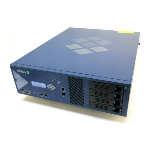
The Network Automation NT-4000 is a 2-U platform that is installed in a seismic equipment rack using mounting
rails and materials that ship with each appliance. For information about rack mounting, see Installing the Network
Automation NT-4000 on page 12.
The front panel comes with a removable front cover.
Figure 1 Network Automation NT-4000, Front View
Front Panel
After you remove the front panel cover, front panel components include the hard disk drives and indicator lights.
Front panel components are illustrated in Figure 2.
Drive LEDs
Power Button
and LED
UID Button and LED
(reserved for future use)
System Health LED
Drive 1
Drive 2
Drive 3
Drive 4
VGA port
Drive 5
Drive 6
Drive 7
Drive 8
Figure 2 Network Automation NT-4000 with Front Panel Cover Removed
The front panel components are described in Table 1.

For the Network Automation NT-4000 Appliance 7
Table 1 Front Panel Components
Disk Drive Front Panel LEDs
The disk drives are located on the appliance front panel. To the right of each drive, two LEDs display connection and
activity status. Table 2 lists the disk drive LED combinations and the states they represent.
Table 2 Disk Drive LED Combinations
Connector Pin Assignments
DB-9, RJ-45 and optical connector pin assignments are described in Figure 3. DB-9 pin assignments follow the
EIA232 standard. To make a serial connection from your management system to the console port, use an RJ-45
rollover cable and two female RJ-45-to-female DB-9 adapters. RJ-45 pin assignments follow IEEE 802.3
specifications.
Component Description
System Health
LED
This LED identifies the overall health of the system.
Green = Normal
Amber = System is degraded
Red = System is in critical condition
Power On/
Standby Button
and Power LED
This button/LED indicates whether the power is on.
Green = System is on
Amber = System is in standby mode
Dark = Disconnected power cord or power supply failure
Disk Drives Eight (8) hot-swappable hard disk drives configured in a RAID (Redundant Array of
Independent Disks) 10 array.
Drive LEDs Each disk drive has two LEDs that indicate the connection and activity status of the disk drive.
The inner LED is the Fault/UID LED (amber/blue) and the outer circular LED indicator is the
Online/Activity LED (green). For information about drive LED combinations, see Table 2.
USB Ports Reserved for future use.
VGA Port Reserved for future use. Port is enabled but unsupported.
Online/Activity LED
(Green) Fault/UID LED
(Amber/Blue) Description
Off or circulating green Steady green The drive is operating normally.
Off or circulating green Steady amber The drive has failed, or it has received a predictive failure alert.

Introduction
8 Infoblox Installation Guide
Figure 3 Pin Assignments and RJ-45 Port Labeling
Rear Panel
The Network Automation NT-4000 appliance provides dual AC power supplies. Power supplies are hot swappable;
any single power supply can be replaced without disrupting the operations of the appliance. The Network
Automation NT-4000 also provides two active RJ-45 Gigabit Ethernet interfaces that operate as MGMT port and LAN1
port in the system. The port assignments are from left to right and reflect port assignments as shown in Figure 4
and listed in Table 3.
21 345
6789
Link Activity
78653421
DB-9 Connector Pin Assignments
Pin Signal Direction
1 (not used)
2 Receive Input
3 Transmit Output
4 DTE Ready Output
5 Ground —
6 DCE Ready Input
7 RTS (Request to Send) Output
8 CTS (Clear to Send) Output
9 (not used)
(Looking into the console
port on an Infoblox
appliance)
RJ-45 Connector Pin Assignments
Pin 10Base-T
100Base-T
Signal
1000Base-T
Signal T568A
Straight-Through
Wire Color
T568B
Straight-Through
Wire Color
1Transmit+ BI_DA+ White/Green White/Orange
2Transmit- BI_DA- Green Orange
3Receive+ BI_DB+ White/Orange White/Green
4 (not used) BI_DC+ Blue Blue
5 (not used) BI_DC- White/Blue White/Blue
6Receive- BI_DB- Orange Green
7 (not used) BI_DD+ White/Brown White/Brown
8 (not used) BI_DD- Brown Brown
RJ-45 Ethernet Ports
Legend: BI_D = bidirectional; A, B, C, D = wire pairings
(Looking into RJ-45
Ethernet ports on an
Infoblox appliance)
Male DB-9 Console Port

For the Network Automation NT-4000 Appliance 9
Figure 4 Network Automation NT-4000, Rear View with RJ-45 Gigabit Ethernet Ports
Table 3 Rear Panel Components
Component Description
IPMI Port Reserved for future use. Port is active but unsupported.
Console Port A male DB-9 serial port for a console connection to change basic configuration settings
and view basic system functions through the CLI (command line interface).
Only connect a properly grounded USB-to-Serial dongle to the serial console port. If the
dongle is connected to a laptop, this laptop must be grounded properly as well. Failure
to do so may result in damage to the serial console port of the Infoblox appliance.
Infoblox is not responsible for such damage.
MGMT Port A 10/100/1000-Mbps gigabit Ethernet port used for appliance management. You must
use the MGMT port for initial appliance setup and for primary system operation. The
MGMT port may also be used for scan interface connections to managed networks.
Infoblox recommends retaining the MGMT port exclusively for appliance management
traffic.
LAN1 Port A 10/100/1000-Mbps gigabit Ethernet port that is used for scan interface connections
to managed networks. You can enable the LAN1 port and define its use through the GUI
after the initial setup. For related information, see Configuring Scan Interfaces on page
40 of the Network Automation Administrator’s Guide, Release 6.9.
MGMT
(inactive) LAN1LAN2
Power
Supply 1
Power
Supply 2
Power Supply
Status LEDs
IPMI Port
UID
Console Port UID Light

Introduction
10 Infoblox Installation Guide
System, Environmental, and Power Specifications
System specifications describe the physical characteristics of each appliance. Environmental specifications
describe the temperature and moisture limits it can withstand. Power specifications describe the electrical range
within which the appliance circuitry can operate.
System Specifications
•Form Factor: 2-U rack-mountable appliance
•Dimensions: 3.44” H x 17.54” W x 27.5” D (8.75 cm H x 44.55 cm W x 69.85 cm D)
•Weight: Approximately 61.00 pounds (27.66 kg)
•Ethernet Ports: MGMT, HA, LAN1, LAN2 – auto-sensing 10Base-T/100Base-T/1000Base-T
•Serial Port: DB-9 (9600/8n1, Xon/Xoff)
•USB Ports: Two USBs 2.0/1.1 compliant
•LCD Panel: LCD (liquid crystal display) with input buttons
Environmental Specifications
•Operating Temperature: 41 to 95 degrees F (5 to 35 degrees C)
•Storage Temperature: -13 to 158 degrees F (-25 to 70 degrees C)
•Operating relative Humidity: 10% to 90% (non-condensing)
Electrical Power Specifications
•DC Power Supply: 48v 750W GRND TERM, RING, VIN 12-10 AWG #10
—Nominal Input Voltage: 48VDC
—Nominal Input Current: 9.6A
—Maximum Power Draw: 460W
LAN2 Port A 10/100/1000-Mbps gigabit Ethernet port that is used for scan interface connections
to managed networks. You can enable the LAN2 port and define its use through the GUI
after the initial setup. For related information, see Configuring Scan Interfaces on page
40 of the Network Automation Administrator’s Guide, Release 6.9.
USB Ports Reserved for future use.
Power Supplies Each of the two redundant power supplies has a power outlet for connecting the
appliance to a standard AC power source.
Power Supply LEDs Green = Normal
Off = System is off or power supply has failed.
UID LED Turns blue to indicate the system is currently being interacted with in the rack. Turned on
by pressing the UID button on the front panel. See Table 1.
Component Description

For the Network Automation NT-4000 Appliance 11
—Heat Output (BTU/hour): 1570 Maximum
—Maximum Peak Power: 750 W at 48V DC input
•AC Power Supply: 100 to 240VAC 750W (Maximum)
—Rated Input Frequency: 50 Hz to 60 Hz
—Rated Input Current: 4.6A at 100V AC, 2.3A at 200V AC
—Rated Input Power: 460W at 100V to 240V AC input
—Heat Output (BTU/hour): 1570 at 100V to 240V AC input
—Maximum Peak Power: 750 W at 100V to 240V AC input

For the Network Automation NT-4000 Appliance 12

For the Network Automation NT-4000 Appliance 12
Installing the Network Automation NT-4000
Note: The Network Automation NT-4000 system must be installed in a four-post seismic rack.
The Network Automation NT-4000 appliance ships with mounting rails, side rails, and an accessory kit that contains
mounting hardware. To mount the appliance to a seismic rack, you also need the following:
•M5 rack screws that fit the seismic rack
•Round-hole M5 cage nuts for use with the seismic rack
•A screwdriver
Rack Mounting Safety Requirements
The following space and airflow requirements are required for Network Automation NT-4000 system operation:
•Minimum clearance of 63.5 cm (25 in) in front of the rack
•Minimum clearance of 76.2cm (30 in) in the rear of the rack
•Minimum clearance of 121.9 cm (48 in) from the back of the rack to the back of another rack or row of
racks
The Network Automation NT-4000 draws air in through the front of the chassis and expels air through the rear.
Adequate ventilation is required to allow ambient room air to enter the chassis and to be expelled from the rear of
the chassis.
To mount the appliance to a seismic rack, follow the instructions bundled with the rack-mounting kit in the NT-4000
Rev. 2 shipping box.
1. Unscrew the snap-in screws from the mounting rails and discard.
2. Install the round-hole M5 cage nuts in the appropriate rack hole positions where you want to install the
appliance. Ensure that you install two cage nuts on the front and two on the back of each rail, as shown in
Figure 5. Note that the square-hole cage nuts that ship with the accessory kit do not fit in the seismic rack.

Installing the Network Automation NT-4000
13 Infoblox Installation Guide
Figure 5 Installing the Round-Hole M5 Cage Nuts
3. Line up a mounting rail with the cage nuts, and attach the mounting rail to the rack with the M5 screws,
ensuring that the front end of each mounting rail connects to the front of the rack.
Note: Ensure that both rail assemblies are correctly level!
4. Repeat steps 1 to 3 for the other mounting rail.
5. Slide out the side rails from each mounting rail and press the flange that holds each side rail in place. Then pull
out each of the side rails from the assembly.
Make sure to keep track of the front end of each rail.
6. Align each side rail to the appliance and snap them in place.
7. With one person on each side, lift the appliance and position it in front of the rack.
8. Align the side rails on each side of the appliance with the mounting rails on the seismic rack.
9. Slide the appliance onto the mounting rails and into the rack. As you slide it into place, the catch mechanisms
will click, indicating that you can safely withdraw the system from the rack without accidentally pulling it free.
10. Snap the Network Automation NT-4000 appliance into place, and fasten it to the rack using the retainer screws
provided in the accessory kit. (For further information, refer to the instructions shipped with the accessory kit.)
11. Pull down the retention levers on both sides of the appliance, and insert the retainer screws on both sides, as
indicated in Figure 6.
Side Rail
Mounting Rail
Cage
Screws

For the Network Automation NT-4000 Appliance 14
Figure 6 Pulling Down the Retention Levers on Front Panel for Retainer Screw Installation
Powering On the Appliance
The Network Automation NT-4000 ships with two (2) hot-swappable redundant AC power supply modules. Infoblox
recommends using the power cables shipped with the appliance to connect each power supply to separate power
circuits. In the event of a power failure on one circuit, the appliance can then operate on the other.
To power the appliance:
•For each power supply, connect a power cable between the power connector on the back of the appliance and
a properly grounded and rated power circuit that meets the provisions of the current edition of the National
Electrical Code, or other wiring rules that apply to your location. Make sure that the outlet is near the
appliance and is easily accessible.
Cabling the Appliance to a Network
Use one or more Category 5/6 Ethernet cables to connect the Network Automation NT-4000 appliance to the
network.
The Network Automation NT-4000 appliance does not need a monitor, keyboard, or mouse for normal operation. It
only needs an Ethernet connection. Follow these steps to connect the appliance to your network:
1. Configure the appliance to use one port (same port for both system administration and network analysis):
Using a straight-through RJ45 Ethernet cable, connect from the LAN1 Ethernet connector on the rear of the
appliance to an available Ethernet connection on the network (as labeled in Figure 4).
or
Configure the appliance to use two ports (the MGMT port for system administration and the SCAN port for
network analysis):
Using straight-through RJ45 Ethernet cables:
a. Connect from the MGMT Ethernet connector on the appliance rear panel (as labeled in Figure 4) to the
network supporting your management systems.
Pull retention levers down to install retainer screws
(one each side)

Installing the Network Automation NT-4000
15 Infoblox Installation Guide
b. Connect from the LAN1 Ethernet connector on the appliance front panel to an available Ethernet
connection on the network that Network Automation will be analyzing.
c. Optionally, connect from the LAN2 Ethernet connector on the appliance front panel to an available
Ethernet connection on the network that Network Automation will be analyzing.
Note: The Network Automation NT-4000 appliance supports 10/100/1000Mbps network connections.
2. After connecting the network cables, plug the appliance into an AC power source.
3. Verify that the green Link LED on the RJ45 port is lit, indicating a good connection to your network. If possible,
verify that the link indicator is lit on the network hub or switch port to which the appliance is connected.
4. Figure 7 illustrates a typical single-port connection.
Figure 7 Cabling a Single Network Automation NT-4000 Appliance to a Network
Note: By default, the Infoblox appliance automatically negotiates the optimal connection speed and transmission
type (full or half duplex) on the physical links between its LAN1, LAN2 and MGMT ports and the Ethernet ports on
neighboring devices.
5. Use the Infoblox GUI to access the Infoblox appliance from a management system. Through the Infoblox GUI,
you can set up and administer the appliance. For management system requirements and access instructions,
see Initial Network Automation Appliance Configuration on page 16.
When cabling a single Infoblox appliance to the network, connect an Ethernet cable
from the MGMT port on the appliance to a switch or router.
Management
Console Switch/Router
Network Automation
Appliance

For the Network Automation NT-4000 Appliance 16
Initial Network Automation Appliance
Configuration
The management system is the computer from which you configure and monitor the Infoblox Network Automation
appliance. You can access the appliance from the management system remotely across an Ethernet network or
directly through a serial cable.
Note: The computer used as the management system must support a minimum screen resolution of 1280x800.
After completing the steps in Cabling the Appliance to a Network on page 14, you can make an HTTPS connection to
the appliance and access the Infoblox Network Automation GUI using one of the supported Internet Web browsers
listed in the Release Notes for the software release installed in your system.
For command-line operation, you can make a terminal console connection through an SSHv2 client. You can also
access the CLI by connecting a serial cable directly from the console port of a management system to the console
port on the appliance, and then using a terminal emulation program.
Note: If you wish to configure the Network Automation appliance for IPv6 connectivity, see the later section,
Configuring a Network Automation Appliance for IPv4 and IPv6.
Network Automation equally supports IPv4 and IPv6 networks, and reports and manages all devices running IPv4
and/or IPv6 protocols.
Configuring the Management System
The Network Automation appliance listens on the private IP address 169.254.1.1/24, which can be used at any time
to configure the system. The easiest way to access the appliance on that address is to temporarily configure your
workstation to use an address on the same subnet, such as 169.254.1.5/24 (or any other address on the same
subnet not occupied by another device).
Depending on the operating system, the procedure to configure your workstation can be slightly different. The
following procedure is for systems running Windows 7:

Initial Network Automation Appliance Configuration
17 Infoblox Installation Guide
1. From the Start menu, select Control Panel.
2. In the Control Panel dialog box, click Network and Sharing Center.
3. In the Network Connections dialog box, click Change Adapter Settings.
4. Right-click the icon for the Ethernet interface you wish to change (Local Area Connection, for example), and
choose Properties from the shortcut menu.
5. In the Local Area Connection Properties dialog box, select Internet Protocol Version 4 (TCP/IPv4) in the Network
Components list, and then click Properties.
6. In the Internet Protocol (TCP/IP) Properties dialog box, select Use the following IP address, and then fill in the
IP address and Subnet mask fields using the IP address 169.254.1.5 and subnet mask 255.255.255.0.
7. Click OK in the Internet Protocol (TCP/IP) Properties and Local Area Connection Properties dialog boxes.
(Depending on your operating system, you might need to reboot your computer.)
Note: This address change is necessary only for the initial setup of Network Automation. Once the setup is
complete, return your workstation to its prior configuration.
8. Click Close in the Local Area Connections Status dialog box.
9. Temporarily disconnect the Network Automation appliance from the network by unplugging the Ethernet cable
from the MGMT port of the appliance.
10. Obtain an Ethernet cross-over cable and connect your computer to the MGMT port using the cross-over cable.
11. Use an SSH client to access Network Automation at the IP address 169.254.1.1.
12. Log in with user name admin and password admin.
13. Continue the configuration by following the instructions described in Configuring a Network Automation
Appliance for IPv4 and IPv6 on page 18.
Notes on Windows IPv6 Configuration
Of course, users can manage Network Automation on an IPv6 network. The Network Automation Management port
has its own factory default link-local IPv6 address that is unique on its connected subnet. The default IPv6 address
derives from the Ethernet MAC address of the Management interface (MGMT).
You must use a Windows 7 system to configure Network Automation to run on an IPv6 network, because Windows
7 natively supports IPv6.
To configure a new Infoblox Network Automation appliance to be managed through IPv6, do the following:
1. Reboot Windows 7, ensure that it is enabled for IPv6 networking, and connect it to the management (MGMT)
port of the Network Automation appliance, using a standard Ethernet cable.
2. On the Windows 7 system, open a DOS command line window and run ipconfig.
Check the listing in the Local Area Connection section of the ipconfig listing, and make a note of the interface
number associated with the PC’s IPv6 Link Local address. The IPv6 value will have an fe80: prefix and end
with a %* designator, such as fe80:505:ac3b:49b7:dc38%15. The value 15 in this example is the interface
number, which will vary with each client.
3. In a Windows command line, run the following command:

For the Network Automation NT-4000 Appliance 18
netsh interface ipv6 show neighbor
4. Find the Interface *: Local Area Connection section (the * corresponds to the interface number for your PC
system’s IPv6 address). No entry should be present in this category for any address starting with the fe80:
prefix.
5. In the Windows PC’s command line, run a multicast IPv6 ping to all nodes on the subnet where the
Management port is running. This executes a multicast IPv6 ping to the Network Automation management port
connected to the PC.
In the Windows command prompt, run the following command:
ping -6 -n 5 ff02::1
Allow the command to complete whether or not responses occur.
6. In the Windows PC’s command line, run the following command a second time:
netsh interface ipv6 show neighbor
The MGMT port IPv6 link-local address should now appear in the neighbor table under the Interface xx: Local
Area Connection section, similar to the following:
fe80::230:48ff:febc:97da 00-30-48-bc-97-da Reachable
This is the link-local address of the Network Automation appliance management port (MGMT).
7. Open an SSH client session to the Network Automation CLI at the IPv6 address shown in Step 6 along with the
interface number. Log in with the factory default username/password admin/admin.
Next, you assign a globally routable static IPv6 address on the management port.
8. Proceed with appliance configuration as described in Configuring a Network Automation Appliance for IPv4 and
IPv6.
Configuring a Network Automation Appliance for IPv4 and IPv6
If Network Automation uses DHCP, make a note of the IP address assigned to Network Automation, and then use the
Setup Wizard as described in Configuring Network Automation Using the Setup Wizard in the Network Automation
Administrator’s Guide.
Note: The Network Automation appliance supports dual-stack connectivity for reachability on both IPv4 and IPv6
networks. You can use either or both.
Otherwise, configure IP addresses as follows:
1. At the CLI (command line interface) command prompt, enter configure server, and specify the following:
2. Enter the new Database Name and press Enter.
Database Name is a descriptive name for this deployment. It is used in reports
titles, headers, etc.
Recommended: Begin name with uppercase letter.
Database Name []: Corp100_west
3. For the first-time installation, you can choose to generate a new HTTPS certificate.

Initial Network Automation Appliance Configuration
19 Infoblox Installation Guide
Do you want to generate a new HTTPS Certificate? (y/n) [n]: y
4. Enter the local domain name in which the controller resides. This value is used for truncating device names in
Network Automation data sets throughout the system.
Domain Name 1 (e.g., example.com) []: corp100.com
Domain Name 2 (optional) []:
5. Enter the time server IP address if one is available or is necessary:
Time Server [us.pool.ntp.org]:
6. Enter the time zone region by typing in the suggested numeric value from the list.
Enter choice (0-47) [0]: 45
7. Enter the time zone location by typing in the suggested numeric value from the list:
Choose a location within your time zone.
0. Alaska 1. Aleutian 2. Arizona 3. Central
4. East-Indiana 5. Eastern 6. Hawaii 7. Indiana-Starke
8. Michigan 9. Mountain 10. Pacific 11. Samoa
Enter choice (0-11) [0]: 10
8. Follow the steps for configuring the management port IP settings:
+++ Configuring Management Port Settings
You must configure an IPv4 or IPv6 address/mask on the management port.
Network Automation can perform analysis from the management port or a separate
scan port.
IP Address (optional) []: 10.120.25.212
Subnet Mask (optional) []: 255.255.255.0
IPv6 Address (optional) []:
IPv6 Prefix (optional):
You must provide either an IPv4 gateway, an IPv6 gateway, or both.
IPv4 Default Gateway (optional) []: 10.120.25.1
IPv6 Default Gateway (optional) []:
Note: You must provide either an IPv4 or IPv6 gateway address, or both, depending on the Network Automation
IP address.
The configure server command then requests configuration of the Scan port if you are running two-port
configuration:
Do you want to configure the Scan Port? <y/n> [n]:
Entering N instructs the configure server command to skip IP configuration for the Scan port.
Table of contents
Other Infoblox Network Accessories manuals
Popular Network Accessories manuals by other brands

Clearfield
Clearfield FieldSmart Makwa FDH installation manual
Viking
Viking PROX-2 Technical practice
ZyXEL Communications
ZyXEL Communications NetAtlas user guide

Teltonika
Teltonika VoiceUSB/G10 user manual
Paradyne
Paradyne Hotwire 6038 installation instructions
Altinex
Altinex Tilt 'N Plug TNP100UN user guide
Extreme Networks
Extreme Networks GBX Installation and user guide
METRObility Optical Systems
METRObility Optical Systems R711-11 Installation & user guide
AMG Systems
AMG Systems AMG2747-SF instruction manual
Extreme Networks
Extreme Networks Auto Configuration Configuration
Black Box
Black Box LB0010A-U24-R2 Specifications

Simado
Simado GDT11 System manual
