inform Infocharger User manual

Infocharger
DC POWER SUPPLY/BATTERY CHARGER

Important Notices!
Thank you for choosing NFORM’s nfocharger system. This product can be used for both battery
charger and DC power supply applications.
For the staff and equipment safety it is necessary for the users to fully read and save this manual
before working on this equipment.
Description of the Symbols
MPORTANT NOT CE! Please follow the instructions.
L FE R SK! Please follow the instructions
DANGER! Please follow the instructions otherwise the unit can be damaged or user can be hurt

Contents
1
Safety ...................................................................................................................................................... 1
2
System Description ................................................................................................................................ 2
3
Installation ............................................................................................................................................. 4
3rd1
Handling .............................................................................................................................................................................4
3rd2
Storage.................................................................................................................................................................................4
3rd3
Positioning..........................................................................................................................................................................4
3rd4
Connections .......................................................................................................................................................................5
3rd4.1
Ground (Earth) Connection ...................................................................................................................................5
3rd4.2
nput connection.......................................................................................................................................................5
3rd4.3
Battery connection....................................................................................................................................................5
3rd4.4
Output connection ...................................................................................................................................................5
4
Switch On an Switch OFF proce ures................................................................................................. 6
4th1
System Switch ON ............................................................................................................................................................6
4th2
System Switch OFF ..........................................................................................................................................................6
5
Operating Instructions........................................................................................................................... 7
5th1
Unit Operation ..................................................................................................................................................................7
5th1.1
Operation modes ......................................................................................................................................................7
5th2
Displays...............................................................................................................................................................................8
5th2.1.1
LCD Display.................................................................................................................................................................. 8
5th2.1.2
Buttons .........................................................................................................................................................................10
There are mainly four buttons in the front panel. The functionalities of the buttons are given below. .....................10
6
Optional Mo ules ................................................................................................................................. 11
7
Maintenance..........................................................................................................................................12
8
Trouble Shouting ..................................................................................................................................13
9
Technical Specifications .......................................................................................................................14


NFOCHARGER 1
1Safety
For the staff and equipment safety, it is necessary for the users to fully read and
understand this manual for DC Power Supply/Battery Charger before installation and
operation.
•Avoi the su en temperature changes, which can cause con ensation insi e the
battery charger. Otherwise, wait at least for two hours before switching on.
•This pro uct shoul be installe accor ing to the instructions efine at chapter
3.3 ‘Positioning’.
•Do not close ventilation holes or other openings.
•Keep away the liqui an soli object entry insi e the unit.
•Installation an commissioning have to be one by authorize technical service.
•Earth ( Groun ) connection shoul be one.
•Do not plug in/off the communication interface cables uring ba weather
con itions with lightning.
•To avoi the risk of fire, all the connections have to be one accor ing to the
suggeste cable cross-sections. The cables shoul be isolate type an properly
installe .
•Do not connect excee ing loa than charger’s nominal power to the output.
•Maintenance an service of the equipment shoul be one by authorize
technical service staff.
•In case of emergency ( amage of the cabinet, front panel or connections etc.)
switch off the battery charger, isconnect the input supply an inform the
authorize technical service staff.
•The unit shoul be packe properly if it is nee e to be move .

2 NF561-Y01-U105-1-00
2System Description
DC Power Supply Operation Mo e
f the equipment is being ordered as DC Power Supply, then the unit supplies a limited voltage and
current value that is adjusted from the front panel to the connected DC load. The output voltage and
current limits can be easily adjusted separately from the SETT NGS menu on the LCD panel.
Battery Charger Operation Mo e
The equipment that is ordered as battery charger has the following specifications. This operation mode
has 4 graduated charging level depending on the battery type. These are initial charge, float charge, boost
charge and temperature or auto controlled charging types. The charge voltages
per cell ;
for initial charge: 2.04V, for float charge: 2.23V, for boost charge: 2.375V, for temperature controlled
charge ; 2.17V at 0
0
C / 2.29V at 50
0
C. These are factory set values, and temperature controlled values can
be set from front panel according to the battery type.
LVD ( Low Voltage Disconnector ) can be included to the unit as an option. This function protects the
batteries from deep discharge by disconnecting them from output during battery mode when the mains is
absent.
Additionally, the dry contact alarm card is an optional feature with its automation functionality.
SYSTEM BLOCK DIAGRAM

NFOCHARGER 3
Input an output EMI filters
These filters prevent electromagnetic interference between nfocharger, mains and loads. (EM –
electromagnetic interference)
Your battery charger and loads are protected against high voltage.
Power Factor Correction
When the power factor is 1, all the energy supplied by the source is consumed by the load
DC / AC Inverter
The inverter helps to obtain a very constant AC voltage level at the output by using DC voltage at the boost’s
rectifier output.
Rectifier
This unit draws on the mains the power required to supply the inverter and to recharge the batteries. The
alternating input voltage is rectified and distributed to the batteries.
Low Voltage Protection(Optional)
This type of protection is used as optional to prevent the deep discharge of the loads in the absence of the
power at mains, and this voltage level can be adjustable at the front panel.
Your Battery Charger’ features an benefits :
Feature
Benefit
PWM technology
Transformerless design Compact design, small dimensions and low weight
Microprocessor controller To use all the sources in optimum level.
To observe carefully the failure conditions
PFC technology
High input power factor
To consume low reactive power
Not to load the installation extra (cables, transformers, generators
etc.)
Clean power for the mains.
Wide input voltage tolerance
(on-line operation even the mains is
between 80 – 280 V )
This helps to reduce battery usage and guarantees battery to be fully
charged and extends the battery life time.
On-line double conversion
topology
The output voltage of the nfocharger is DC. nfocharger input total
harmonic distortion is very low. This is very important for both the
systems and batteries which are supplied by nfocharger.
Temperature Management To calculate overloading time in a reliable way.
To protect against over temperature.
Effective output voltage regulation : (output voltage is not affected by changes on the mains input and load level.)
High efficiency ( low power consumption)

4 NF561-Y01-U105-1-00
3Installation
Check if the nfocharger has been subjected to any damage before unpacking it. f you notice any
damage, please contact to transport firm. Check if all the additional parts have been supplied with the
battery charger.
Please make sure that the packing contains the following
• Infocharger
• User Manual
• Test Report
Before the installation, please check if your nfocharger is customized following your special
requirements (if any).
n standard battery charger the output voltage and frequency can be adjustable between 0-30Vs and
60-135Vs
.
3r 1 Han ling
f needed to move the battery charger, it is obligatory to pack the unit. t is suggested to keep the
original packing.
3r 2 Storage
Please store the battery charger in an environment where the temperature is between –15 °C and +55 °C no
receipt of direct sunlight, far from the heating, in a dry place. Environmental humidity must be between %20
and %95 (non-condensing).
3r 3 Positioning
nfocharger and battery cabinet(if any) have to be positioned in an environment;
•No irect sun access,
•Must be ry,
•Far from the heating equipments
•No excessive ust
•Well-ventilate
•In or er to maintain a equate ventilation of Infocharger an battery cabinets (if
any), ensure the air vents are not blocke an leave at least 20 cm space at the rear
si e of the unit for ventilation.

NFOCHARGER 5
3r 4 Connections
Connections must be done by authorized technical service staff. Life risk for user!
Temperature changes such as from cold to hot environment can cause condensation. t is dangerous
to operate the nfocharger. Please wait at least two hours before making the connections.
Connection terminals are in the rear side of the battery charger. Please take out the cover of the rear side to
make the connections.
Standard nfocharger connections are shown below.
Please follow the instructions as explained below.
3r 4.1 Groun (Earth) Connection
nforcharger ground (earth) connections have to be done.
The input ground clemens of the nfocharger should be connected to a reliable (low resisted) ground
The grounding connection of the loads can be done over the output grounding contactor.
The grounding connection of the external battery cabinet(if any) should be done over the same battery
grounding contactor.
The connection between the grounding unit of the nfocharger and the ground can be made according to the
minimum cross-sectioned cables which are given in the technical specifications table below.
3r 4.2 Input connection
The connection between the distribution frame and nfocharger for phase, neutral and ground are explained
as below
For single phase the R, Neutral and ground must be connected to their contactors in the front panel with a
1.5 mm
2
cross-section multi-vein cable
For three phase the R, S, T, Neutral and ground must be connected to their contactors in the front panel with
a 1.5 mm
2
cross-section multi-vein cable
Changes on distribution panel have to be done by authorized persons only.
3r 4.3 Battery connection
The batteries must be connected to the L+(positive) and L-(negative) points properly. The DC power supply
type nfocharger does not have this connection. The batteries have to be connected with an external circuit
breaker.
3r 4.4 Output connection
The clemens on the equipment can be used for the + and – output points. The cables to these clemens are
connected to the fuses and the protection is over the (L+) point.

6 NF561-Y01-U105-1-00
4Switch On an Switch OFF proce ures
4th1 System Switch
ON
After making all the connections mentioned in the previous chapter, you need to switch on to all the
automatic fuses on the front panel, if mains voltage is within the limits, the unit switches on.
nforcharger makes self-test for few seconds to check if everything is normal, and then starts to charge the
batteries or supply the load.
4th2 System Switch OFF
To stop the load to be supplied or the batteries to be charged, please switch off the all automatic fuses in the
front panel.

NFOCHARGER 7
5Operating Instructions
5th1 Unit Operation
5th1.1 Operation mo es
•Infocharger; is esigne for the usage as a battery charger an c power supply.
Output current, voltage an the float charge limits are a justable on the front control
panel easily.
The battery current and voltage characteristics are shown in the figure below
CHARGE CHARACTERISTICS
0
5
10
15
20
25
30
35
1 6 11 16 21 26 31 36 41 46 51
TIME
CURRENT/VOLTAGE
0
0,5
1
1,5
2
2,5
Ibat
Vbat/Cell
Battery current is controlled in a way to keep stable the power transferred to batteries in direct charge zone.
f the voltage passes a certain value, float charging starts. t is applied fixed voltage 2,23V per battery. Float
charging takes 30 minutes. Then it passes to tampon charging. During the tampon charging, it is applied fixed
voltage 2,25V per battery in 25 °C environment temperature. Auto charge voltage is adjustable according to
the environment temperature.
Float
Boost
Oto
8 NF561-Y01-U105-1-00
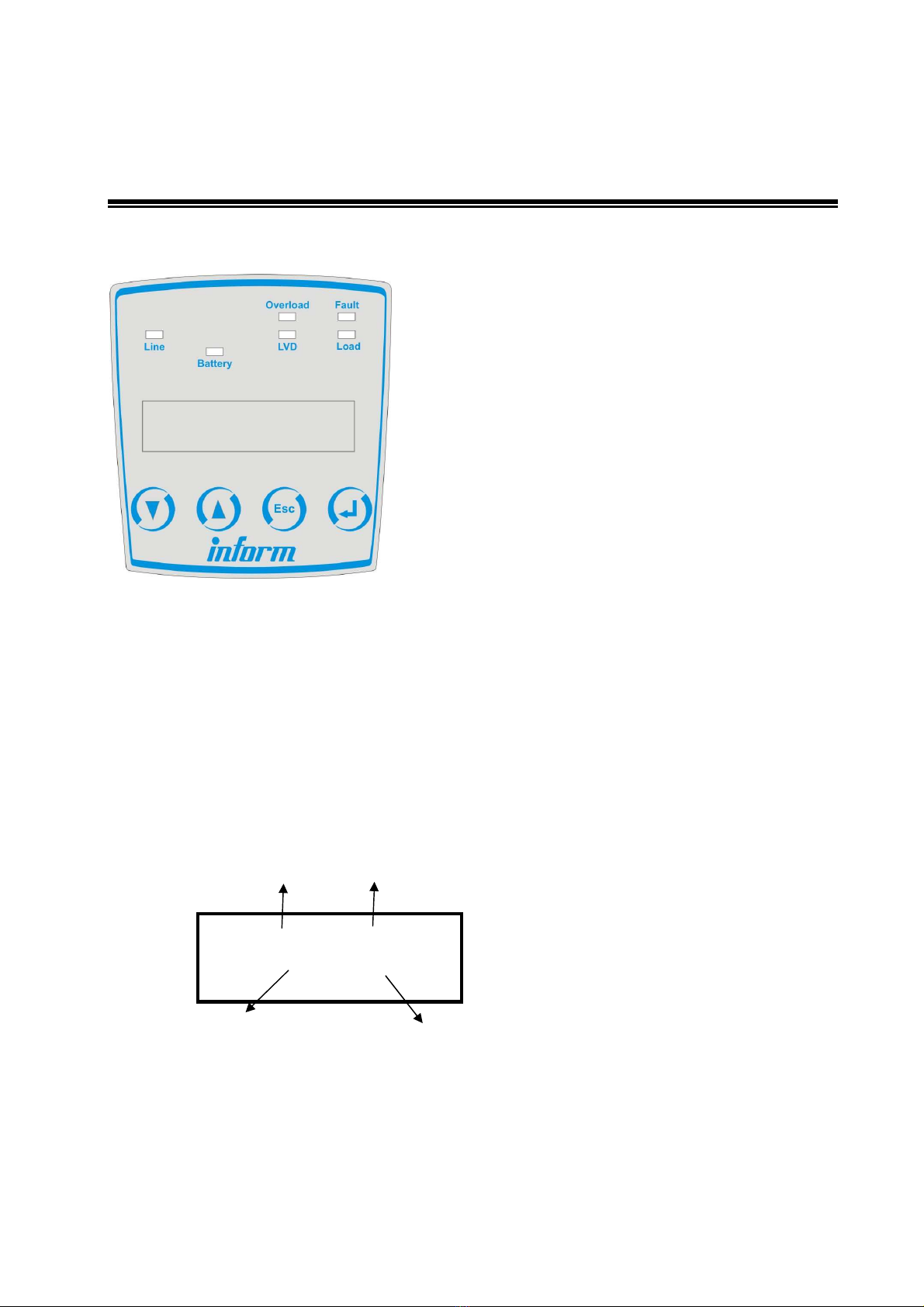
5th2 Displays
The front panel of the nfocharger is shown below:
nfocharger control panel is composed of;
•LCD Display (Liqui crystal isplay),
•LEDs
•Buttons
5th2.1.1
LCD Display
There are mainly four display sections on the control panel as follows
On the “Operation mode” section of the display, the actual operating mode is seen. On the left part of this
display section the following messages can be observed:
DC : It is observe when the unit is in DC power supply mo e.
CHARGER : It is observe when the unit is in battery charger mo e
XXXXX XXXXX
Vo=XXX V Io=XX A
OPERATION
MODE
STATUS
OUTPUT
VOLTAGE
OUTPUT
CURRENT

NFOCHARGER 9
On the “Status mode” section of the display, if the unit is on-line or fault status. On the right part of this
display section the following messages can be observed:
OK : It is observe when the unit is online-
FAULT : It is observe the unit is out of function-
MENU STRUCTURE
1-Analog values
Vbatt : Battery voltage
Ibatt : Battery current
Vloa : Loa voltage
Iloa : Loa current
Vinput : Input voltage
Tre : Internal temperature of the charger
Ifan : Fan current
Tenv: Environmental(ambient) temperature
2-A justments
Operational mo e as DC or CH: DC power supply or CH battery charger
If DC mo e is selecte -(DC power supply)
Vout :It is a justable between 0 –
255, the output voltage is a justable
between values 0-30, 0-60, 0-140 VDC .
Iout : It is a justable between 0-255, the current is a justable between
values 0-60, 0-30, 0-15 A accor ing to the type of Infocharger.
If CH mo e is selecte -(Battery charger)
Battery capacity: It is between 0-1000 Ah
Charge current: It is a justable between 0-100%
Low voltage protection: It is a justable between 19-22, 38-44 , 85-100VDC
Temperature controlle charging = PRESENT OR NOT
0°
°°
°C volt VALUE: A justable epen ing on the type (battery charging voltage at 0°
°°
°C )
50°
°°
°C volt VALUE: ifferent epen ing on type(battery charging voltage at 0°
°°
°C )
Max. charging time: 0-10 hours
Low voltage limit: LVD low voltage limit DC-
3- ALARMS
Vinput: In case of the voltage at mains is out of limit value
Vbatt : In case of the battery current is out of limit value
Vloa : In case of the loa voltage is out of limit value

10 NF561-Y01-U105-1-00
Tcharger :In case of the measure value over the ventilator is higher than limit
value.
FAN : Shows the ventilator current control an ventilator failure.
Tenv: In case of the operating temperature is higher than the limit value
CURRENT LIMIT: Shows the output current value is equal to (nominal) current
or greater than the (nominal) current
LVD: When the charger is at charger mo e, it shows that the battery voltage is
below the a juste value.
EEPROM: When the memory log is not functioning.
3-UNIT INFORMATION
A ress : between 0-8
Ver:
Seri no: Serial number
5th2.1.2
Buttons
There are mainly four buttons in the front panel. The functionalities of the buttons are given below.
button: Scroll own to next line
button: Scroll up to previous line
button: Exit from the active menu.
button: Enter to active menu.
TREE STRUCTURE OF THREE PHASE INFOCHARGER MENU SCREEN
Esc
Vbat
XXX V
MENU
MENU
MENU
MENU
MENU
ANALOG
SETT NGS
ANALOG
VALUES
ANALOG
ANALOG
VALUES
ANALOG
VALUES
ANALOG
VALUES
ANALOG
VALUES
Batt.Capacity
Char. Cur.
Low Voltage
Discon.= XXXXX
Charge with Temp
0
°
C Volt Value
50
°
C Volt Value
Max Charge Time
Low Voltage
Limit= XXX VDC
Charge Step
Alarm Status
Vbat: NORMAL
Tred: NORMAL
Tenvrm:
NORMAL
LVD: NORM
AL
Type = 110 VDC
Version = 1.6
ANAL
OG
ALAR
M

NFOCHARGER 11
6Optional Mo ules
There are mainly two optional modules for the nfocharger
These are;
1- LVD Module: This module prevents the loads and batteries to be deeply discharged. A delay is
used for the separation of the batteries from the load. This delay is on L+ side. The voltage level of
this separation process can be chosen on the control panel. This voltage level can not be less than
1,65V which is the minimum voltage level per cell.
2- Delay module: This module is designed for the automation processes and has 8 delay output
These are as follows;
a. VBAT OUL: Battery voltage is out of limit
b. V N OUL : Mains voltage is out of limit
c. VLOAD OUL: Load voltage is out of limit
d. TEMP H GH :Ventilator temperature is out of limit
e. FAN FA LURE: Fan failure
f. Empty: Empty
g. TOTAL ALARM: Total Alarm
h. CUR L M: Operating within the current limit

12 NF561-Y01-U105-1-00
7Maintenance
The nfocharger unit does not need maintenance.
f you want to make cleaning on the unit, than you should perform the following:
•Disconnect the loa s
•Bring all the fuses on the unit to “0” position.
•Clean the unit with a slightly moistene cloth.
Do not drop any liquid and solid foreign substance inside the unit.
Do not use a cleaning powder or any other material that may damage the plastic parts.

NFOCHARGER 13
8Trouble Shouting
•In this section, proce ures that shoul be followe , explaine uring an abnormal
con ition of the unit. Before your inform the technical service, rea an apply
carefully things explaine in etail in this section.
•If the fault le on front panel is on; then go to the main menu on front panel an
check what the fault is.
•If the le s on front panel are all off please check input fuses.
•If you can rea the battery an loa voltage on front panel but can not measure the
same voltage at battery an loa then check the battery an loa fuses.
•If there is an over temperature failure, please check the ventilator if it is running.
•If there is a problem with the batteries (boiling or over heating), please check the
battery charge current an voltage on the front panel.
•If you still have problems, please call technical service.
Please note the model and the serial number of the unit which are present on the rear panel label. Describe
the problem with full information.

14 NF561-Y01-U105-1-00
9Technical Specifications
Dimensions
Height 28 cm Width 25 cm
Depth 42 cm
Weight 11,6 kg
Environmental Con itions
Operating 0 ... +50 [°C]
Operating %20 ... %80
Temperature
Storage -15 ... +70 [°C]
Relative Humidity
Storage %20 ... %95
Electrical Specifications
Connection cable’s section area BATTERY INPUT
24V 60A 10mm2 2,5mm2
48V 30A 6mm2 2,5mm2
110V 15A 4mm2 2,5mm2
Input
Nominal Voltage 220V
Nominal Frequency 50Hz
nput voltage range at mains running 90 – 280 V
nput frequency range at mains running 45 Hz – 65 Hz
Power factor( at nominal input voltage) >0,99 @
Current Total Harmonic Distortion (THD)[%] <3%
Efficiency >90%
Output
Output voltage 24VDC 48VDC 110VDC
nitial charge 24,5V 49V 112V
Float charge 26,75V 53,5V 122,6V
Fast charge 28,5V 57V 130,6V
DC Supply 0-30V 0-60V 0-140V
Short circuit current 110% 110% 110%
Output current 60A 30A 15A
Output Voltage fluctuations <30mV <60mV <100mV
Dynamic response 2%< 2%< 2%<
Output protection
Electronical short circuit protection / over current protection /
reverse voltage protection
Stan ar s
Protection Class P 20
EMC EN 50091-2
Performance EN 62040-3, EN 50091-3

NFOCHARGER 15
Safety EN 50091-1
Product Certification = CE
Dimensions
Height 62.5 cm Width 21 cm
Depth 55.5 cm Weight 36,6 kg
Environmental Specifications
Operating 0 ... +50 [°C] Operating %20 ... %80
Temperature
Storage -15 ... +70 [°C] Relative Humidity
Storage %20 ... %95
Electrical Specifications
Connection Cable
Cross Section
OUTPUT
INPUT 1 PH 3 PH
24V 200A 2X25mm
2
10 mm
2
4mm
2
48V 100A 25mm
2
10 mm
2
4mm
2
110V 50A 10 mm
2
10 mm
2
4mm
2
220V 25A 4mm
2
10 mm
2
4mm
2
INPUT
Nominal Voltage 220V Ph-N or 380 Ph-Ph
Nominal Frequency 50Hz
Input voltage range at mains running 176 – 265 V
Input frequency range at mains running 45 Hz – 65 Hz
Power factor( at nominal input voltage) >0,8 @
Efficiency >90%
OUTPUT
Output voltage 24VDC 48VDC 110VDC 220VDC
Initial charge 24,5V 49V 112V 220V
Float charge 26,75V 53,5V 122,6V 240V
Boost charge 28,5V 57V 130,6V 254V
Dc Supply 0-30V 0-60V 0-140V 0-250V
Short circuit current 104% 104% 104% 104%
Output current 200A 100A 50A 25A
Output Voltage fluctuations <100mV <200mV <500mV <1V
Dynamic response 2%< 2%< 2%< 2%<
Output protection Electronically short circuit protection / over current protection /
reverse voltage protection
Standards
Protection Class P 20
EMC EN 50091-2
Performance EN 62040-3, EN 50091-3
Safety EN 50091-1
Product Certification CE, TSEK

16 NF561-Y01-U105-1-00
Cable cross-section area (mm2) Current value absorbed by t he load(Amp.)
1,5 18
4 34
6 44
10 61
16 82
25 108
35 135
50 168
70 207
95 250
120 292
150 335
185 382
240 453
300 504
THESE UN TS ARE G VEN FOR THE MULT -VE NS CABLES.
Table of contents


