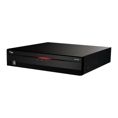
INFRALAN SECURITY ILR-16POE User manual

8/16 Ch. Network Video Recorder
Quick guide

To ensure safe operation, you must observe these operating
instructions as a user:
Before operating the product, please read the entire operating
instructions, observe all operating and safety instructions.
Detailed information and safety instructions can be found in the
operating instructions on the enclosed CD or on the Internet on
the website www.infralan-security.de
-Keep strong magnetic fields away from the network recorder.
-Keep liquids away from the recorder.
-Make sure the network recorder is securely mounted.
-Ensure an uninterrupted power supply when operating with a
permanent voltage source.
-Operate the network recorder only with a suitable voltage
source.
-Operate the network recorder only under the environmental
conditions recommended by the manufacturer.
The conformity has been proven, the corresponding declarations
and documents are deposited with the manufacturer:
EFB Elektronik GmbH, Striegauer Str. 1
33719 Bielefeld - Germany

Regulatory information
EU Conformity Statement
This product and, if applicable, the accessories
supplied with it bear the „CE“ mark and comply
with the applicable harmonized European
standards, which are listed in the Low Voltage
Directive 2006/95 / EC and the EMC Directive
2004/108 / EC.
2012/19/EC (EEAG-directive): Products marked
with this symbol cannot be disposed of as unsorted
municipal waste in the European Union. For proper
recycling, return this product to your local supplier
upon the purchase of equivalent new equipment,
or dispose of it at designated collection points. For
more information see: www.recyclethis.info
2006/66/EC (battery directive): This product
contains a battery that cannot be disposed of as
unsorted municipal waste in the European Union.
See the product documentation for specific
battery information. The battery is marked with
this symbol, which may include lettering to
indicate cadmium (Cd), lead (Pb), or mercury (Hg).
For proper recycling, return the battery to your
supplier or to a designated collection point. For
more information see: www.recyclethis.info

Front Panel
The following figure shows the front panel of NVR:
1. Status Indicators:
• Power: Power indicator turns yellow when system is
running.
• Status: Status indicator blinks red when data is being
read from or written to HDD.
• Tx/Rx: Tx/Rx indictor blinks yellow when network
connection is functioning properly.
2. USB Ports: Connects USB mouse or USB flash memory
devices.
No.
Item
Description
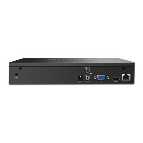
1
Power Supply
AC230V power
2
Audio IN
RCA connector for voice talk input
3
HDMI
Interface
HDMI video output connector.
4
LAN Network
Interface
LAN Network interface to communicate
5
Audio OUT
RCA connector for audio output
6
VGA Interface
VGA Interface
DB9 connector for VGA output.
Display local video output

7
USB Interface
Universal Serial Bus (USB) ports for additional
devices such
as USB mouse and USB Hard Disk Drive (HDD).
8
Ground
Ground (needs to be connected when NVR
starts up).
9
Power Switch
Switch for turning on/off the device.
10
Network
interfaces with
PoE function
Network interface for the recorders and to
provide power over Ethernet.
11
Alarm In/Out
Alarm Input/Output Interface
2 Installation
NOTE:
DVRs/NVRs starting with the latest firmware (see chart,
above) WILL NO LONGER HAVE A DEFAULT PASSWORD. The
user must activate the NVR by creating a password for the
admin account, which can be done in one of four ways:

• Local Activation
1. Power on the DVR/NVR.
-An activation message will appear on the screen prompting the
user to activate the device (Figure 1).
-The username field will be greyed-out with the username set
to admin.
2. Type in a password of your choosing.
-The password strength will be displayed, accompanied by a color
indicator:
• Level 0–Risky (red indicator): Not acceptable
• Level 1–Weak (red indicator): Acceptable
• Level 2–Fair (orange indicator): Acceptable
• Level 3–Strong (blue indicator): Acceptable
-Activation will not be allowed unless the password is of
acceptable strength.
3. Retype the password into the “Confirm Password” field.

Figure 1 Activation Window

4. After an acceptable password has been
created, a confirmation message will appear
on the screen (Figure 2).
5. Press the OK button to proceed.
Figure 2 Activation Window

3 Configure via LAN
Note:
In order to access and configure the network recorder in
the LAN, it must be in the same subnet as your PC. Then
install the IDM (Infralan Device Manager) software to find
and configure the IP address of the network recorder..
The following figure shows the cable connection between
the network recorder and the computer:
Figure 3-1 Cabling in the LAN
Set the IP address oft he recorder to access LAN.
Steps:
1. Install IDM, a software tool that automatically
detects a network recorder in the LAN (see Figure
3-2.
2. Change the IP address and subnet mask as appropriate
Configuration parameters of your computer. Use the following
instructions to align with the IDM software to set the IP
address:

Search for active online devices
After starting, the IDM software automatically scans the
subnet of your computer every 15 minutes Online devices
Figure 3-2 Search for online devices
View device information
Steps:
1). Select the desired device in the device list (see
Figure 3-3). The network parameters of the device are
displayed in the “Modify Network Parameters” field on
the right.
2). Edit the available network parameters (such as
IP address and port number)

3). In the Password box, type the password fort he
device administrator account, and then click Save
to save changes.
Figure
3-3
Selection of equipment
3. Enter the IP address of the network recorder in the
address field of the web browser to access the live
image.
The default IP address is „192.168.1.245“. The
default username is “admin” and the password
is 12345
To access the recorder from different subnets, please
set up the network recorder gateway after login

Change the IP address
Um To view and configure the recorder through a LAN, you must
connect the network recorder to the same subnet as your
computer. Then install the IDM software or client software to
search for and change the IP address of the network recorder. The
modification of the IP address is described, for example by means
of the IDM software.
Steps:
1. Start the IDM Software.
2. Select an active device.
3. Change the IP address so that it has the same subnet as
the computer. To do this either manually change the IP
address or enable the enable DHCP check box.

4. Enter the password to enable your changes to the IP
address.
The IDM Software supports stacking of IP addresses. For
more information, see the User Guide.

4 Access via web browser
Steps:
1. Open the web browser.
2. Enter the IP address of the network recorder (for
example 192.168.1.245) in the address fieldand press
Enter to enter the login dialog.
3. If you do not have access to the recorder via the web browser,
please repeat the step in chapter 3
.
4. Enter your username and password.
5. Click Login
Figure 4-1 Registration dialog
6. Install the plug-in if your browser does it. Download the
plug-in, start the setup, and close your browser before clicking
“Next”

COPYRIGHT © 2017 EFB Elektronik GmbH
EFB Elektronik GmbH
Striegauer Straße 1
33719 Bielefeld - Germany
www.infralan-security.de
Figure 4-2 Plug-in-Download
Figure 4-3 Plug-in-Installation
7. Open the web browser after installing the plug-in and
repeat steps 2-4 to log in.
8. This makes the recorder ready for use.
This manual suits for next models
2
Table of contents
