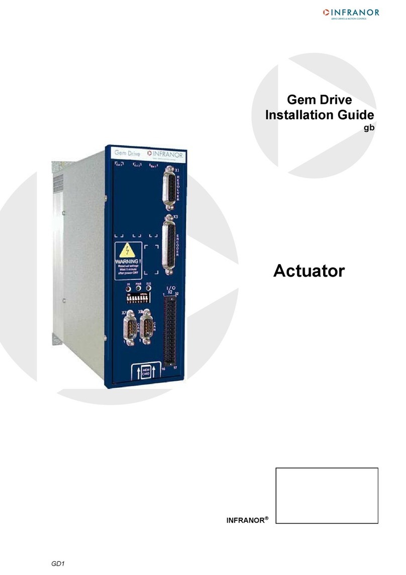
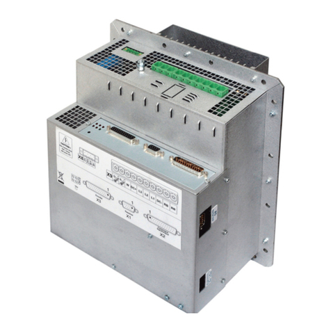
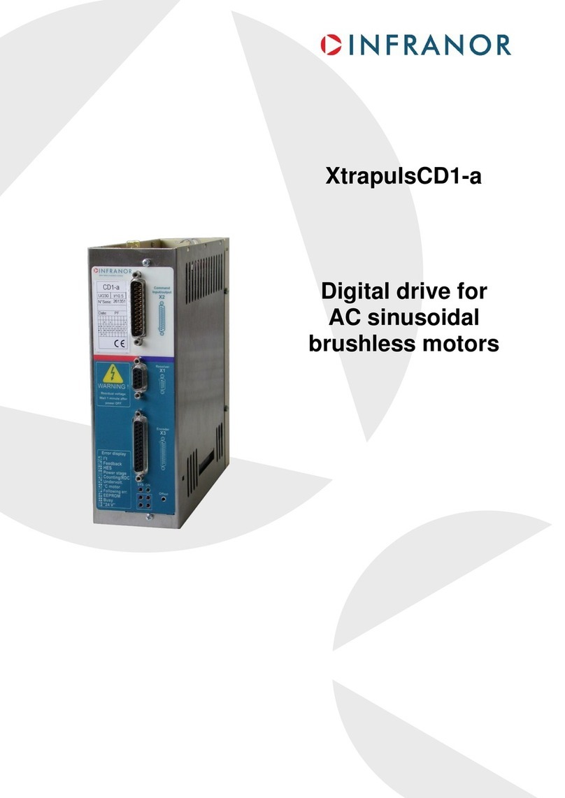
Infranor XtrapulsGem User guide

1
Digital drive
for sinusoidal
synchronous
AC motors
XtrapulsGem
Application
Templates
en

2
XtrapulsGem Application Templates
WARNING
This is a general manual describing a series of servo drives having output capability suitable for driving AC
brushless sinusoidal servo motors.
Please see also:
o XtrapulsGemInstallation Guide for the hardware installation of the drive (mounting, wiring, ...)
o XtrapulsGem STO for the Safe Torque Off function
o XtrapulsGem Encoder output for the encoder output option board description
o XtrapulsGem User Guide for the operation of the drive (commissioning, configuration, ...)
o Gem Drive programming guide for the programming instructions
o Gem Drive Studio software Quick Start manual for the drive parameterization.
Instructions for storage, use after storage, commissioning as well as all technical details require the
MANDATORY reading of the manual before getting the drives operational.
Maintenance procedures should be attempted only by highly skilled technicians having good knowledge
of electronics and servo systems with variable speed (EN 60204-1 standard) and using proper test
equipment.
The conformity with the standards and the "CE" approval is only valid if the items are installed according to the
recommendations of the drive manuals. Connections are the user's responsibility if recommendations and
drawings requirements are not met.
INFRANOR does not assume any responsibility for any physical or material damage due to improper handling or
wrong descriptions of the ordered items.
Any intervention on the items, which is not specified in the manual, will immediately cancel the warranty.
Infranor reserves the right to change any information contained in this manual without notice.
© INFRANOR, February 2010. All rights reserved.
Issue: 1.4
!
ELIMINATION
In order to comply with the 2002/96/EC directive of the European Parliament and of the Council
of 27 January 2003 on waste electrical and electronic equipment (WEEE), all INFRANOR
devices have got a sticker symbolizing a crossed-out wheel dustbin as shown in Appendix
IV of the 2002/96/EC Directive.
This symbol indicates that INFRANOR devices must be eliminated by selective disposal and not
with standard waste.
Any contact with electrical parts, even after power down, may involve physical damage.
Wait for at least 5 minutes after power down before handling the drives (a residual voltage of several
hundreds of volts may remain during a few minutes).
ESD INFORMATION (ElectroStatic Discharge)
INFRANOR drives are conceived to be best protected against electrostatic discharges. However,
some components are particularly sensitive and may be damaged if the drives are not properly
stored and handled.
STORAGE
- The drives must be stored in their original package.
- When taken out of their package, they must be stored positioned on one of their flat metal
surfaces and on a dissipating or electrostatically neutral support.
- Avoid any contact between the drive connectors and material with electrostatic potential
(plastic film, polyester, carpet…).
HANDLING
- If no protection equipment is available (dissipating shoes or bracelets), the drives must be
handled via their metal housing.
-
Never get in contact with the connectors.

3
Contents
XtrapulsPac Application Templates
Contents
PAGE
CONTENTS........................................................................................................................................... 3
CHAPTER 1 - GENERAL...................................................................................................................... 4
1.1 - INTRODUCTION ....................................................................................................................... 4
CHAPTER 2 – BASIC ANALOG SPEED DRIVE TEMPLATE ............................................................. 5
2.1 - "BASIC ANALOG SPEED DRIVE" DESCRIPTION ................................................................... 5
2.2 - "BASIC ANALOG SPEED DRIVE" CONNECTION DIAGRAM.................................................. 6
2.3 - "BASIC ANALOG SPEED DRIVE" CONFIGURATION ............................................................. 6
2.4 - "BASIC ANALOG SPEED DRIVE" COMMISSIONING.............................................................. 6
CHAPTER 3 – ADVANCED ANALOG SPEED DRIVE TEMPLATE .................................................... 8
3.1 - "ADVANCED ANALOG SPEED DRIVE" DESCRIPTION.......................................................... 8
3.2 - "ADVANCED ANALOG SPEED DRIVE" CONNECTION DIAGRAM ...................................... 10
3.3 - "ADVANCED ANALOG SPEED DRIVE" CONFIGURATION .................................................. 10
3.4 - "ADVANCED ANALOG SPEED DRIVE" COMMISSIONING .................................................. 10
CHAPTER 4 – BASIC POSITIONER TEMPLATE ............................................................................. 12
4.1 - "BASIC STAND-ALONE POSITIONER" DESCRIPTION ........................................................ 12
4.2 - "BASIC STAND-ALONE POSITIONER" CONNECTION DIAGRAM....................................... 13
4.3 - "BASIC STAND-ALONE POSITIONER" CONFIGURATION................................................... 13
4.4 - "BASIC STAND-ALONE POSITIONER" COMMISSIONING................................................... 13
CHAPTER 5 – EXTENDED POSITIONER TEMPLATE..................................................................... 15
5.1 - "EXTENDED STAND-ALONE POSITIONER" DESCRIPTION ............................................... 15
5.2 - "EXTENDED STAND-ALONE POSITIONER" CONNECTION DIAGRAM.............................. 16
5.3 - "EXTENDED STAND-ALONE POSITIONER" CONFIGURATION.......................................... 16
5.4 - "EXTENDED STAND-ALONE POSITIONER" COMMISSIONING.......................................... 16
CHAPTER 6 – ADVANCED POSITIONER TEMPLATE .................................................................... 18
6.1 - "ADVANCED STAND-ALONE POSITIONER" DESCRIPTION ............................................... 18
6.2 - "ADVANCED STAND-ALONE POSITIONER" CONNECTION DIAGRAM.............................. 20
6.3 - "ADVANCED STAND-ALONE POSITIONER" CONFIGURATION ......................................... 20
6.4 - "ADVANCED STAND-ALONE POSITIONER" COMMISSIONING.......................................... 20

4Chapter 1 –
General
XtrapulsGem Application Templates
Chapter 1 - General
1.1 - INTRODUCTION
XtrapulsGem all-digital drives with sinusoidal PWM control are servo drives that provide the control of brushless
AC motors with position sensor (resolver, encoder).
The XtrapulsGem drive is a configurable and programmable drive with built-in servo-functions.
XtrapulsGem is a single-axis block including power supply unit and mains filters. It is available in both 230 VAC
and 400/480 VAC mains operated voltages.
It obtains high regulation performances with:
16 bit resolver processing
Multi-standard encoder input
Motor speed up to 25000 rpm.
It includes an SD card interface for the update of firmware and file operation.
It also includes a CAN and RS-232 communication port.
The XtrapulsGem drives communication is based by default on the "CANopen" protocol and drive profile
DS402.
Series XtrapulsGem drives are fully configurable and programmable in order to fit various applications. They can
be used in the following application types:
• Axes controlled by CANopen fieldbus according to the DS402 protocol,
• Stand-alone operation as a motion sequencer with control by means of logic I/Os,
• Traditional analog speed amplifier with +/- 10 V command and position output by A, B, Z encoder signal
emulation (with the Encoder Output option board),
• Stand-alone operation for multi-axis electronic gearing or caming by using the servo mode and the drive
programming capability.
The configuration and parameterization software tool Gem Drive Studio allows a quick configuration of the
XtrapulsGem drives according to the application requirements. Gem Drive Studio also allows the user program
Edit, Compile and Download in the drive.
This manual only describes the quick configuration of the XtrapulsGem servo drive by using the application
templates available in the Gem Drive Studio software.
When an application template is selected in the Drive Configuration library, the XtrapulsGem input and output
functionalities as well as the drive operation are set according to the target application. The Gem Drive Studio
parameterization windows are also adapted to the target application in order to display only the required
parameters and functions. The user can go back to the full configuration mode at any time by selecting the
Expert mode in the Drive Configuration window.
The application templates described in this document are listed below :
- Basic analog speed drive,
- Basic stand-alone positioner,
- Extended stand-alone positioner,
- Advanced analog speed drive,
- Advanced stand-alone positioner.

5
Chapter 2 – Basic analog speed drive application
XtrapulsGem Applicati
on Templates
Chapter 2 – Basic analog speed drive template
2.1 - "BASIC ANALOG SPEED DRIVE" DESCRIPTION
When the XtrapulsGem drive is configured with the Basic Analog Speed Drive template, the motor speed input
command is an analog voltage (± 10 V), and the rotor position monitor is available as two channels A and B in
quadrature and one marker pulse per revolution (the XtrapulsGem drive must be equipped with the encoder
output option board). The maximum motor speed according to a 10 V input voltage is programmable from
100 rpm to 25'000 rpm. The encoder emulation output resolution is also programmable. All values (binary or
decimal) between 64 pulses per revolution and 16384 pulses per revolution (ppr) can be programmed according
to the maximum motor speed. This drive configuration is suitable for conventional DNC controls.
In the Basic Analog Speed Drive configuration, the servo motor can be switched on or off by activating or
deactivating the Enable input. During the operation of the XtrapulsGem drive, the motor acceleration and
deceleration with regard to the ±10 V input voltage variation can be limited by setting the Accel time and the
Decel time parameter value.
The activation of the Limit switch + input inhibits any CW motor rotation and the activation of the Limit switch -
input inhibits any CCW motor rotation.
The activation of the STOP input stops the axis rotation in current limitation or ramping according to the selected
operation.
The RESET input allows to erase any stored drive fault when the cause of the fault release has been cancelled.
The BRAKE output allows to control the motor brake when the drive is enabled and disabled.
The DRIVE ON output is activated when the drive is enabled.
The POWER output is activated when power supply voltage is applied to the drive.
The Ilim analog input (0 to 10 V) allows to limit the motor peak current proportionally to the applied input voltage
(no limitation for 0 V).
The block diagram of the “basic analog speed drive” configuration is presented below.

6Chapter 2 – Basic analog speed drive application
XtrapulsGem Application Templates
2.2 - "BASIC ANALOG SPEED DRIVE" CONNECTION DIAGRAM
2
10
11
3
5
4
12
13
2
4
3
TC
TC
S3
S1
S2
S4
R1
R2
X1
1
X8
X10
X9
1
2
3
1
2
Phase 1
Phase 2
Phase 3
20A max.
20A max
1
2
X12
GD1-uuu/cc/PS-R
+24 Vdc
DC+
DC-
X2
X6, X7
1
2
4
X12
2
3
4
1
28
29
32
31
1
2
3
4
19
30
+
-
230 Vac
-
+
AOK+
AOK-
AC
-
+
3
1
2
1
2
X11 X11 X11 X11
1
2
1
2
UL compliance
only
UL compliance
only
3 φ400Vac
5
24 V
21
23
26
20
STO1
STO2
Ext. reference
STO_OUT
Load
Motor temp.
Motor temp.
Resolver
signal
Resolver
reference
GND
GND
GND
RESOLVER
Motor U phase
Motor V phase
Motor W phase
Braking resistor
Braking resistor
Power
relay
Power
relay
Mains
230 Vac
single-phase
External or
internal
braking
resistor
Mains
3x400V
IN1 = LIMIT+
IN2 = LIMIT-
IN3 = STOP
IN4 = ENABLE
OUT1 = BRAKE
OUT2 = DRIVE ON
24 V Ext. if logic
output used
CAN
GND
brake
+24 Vdc
brake
Motor
brake
24 Vdc/1.5A
24 Vdc
+/-15%
isolated See UL fuses
table
See UL fuses
table
4 A UL listed
4 A UL listed
MOTOR
GND
24 Vdc power supply isolated
from the 230 Vac mains
Motor brake +
Motor brake -
OTHER AXES
GD1-uuu/cc/00-0
Total power of the application
< 4 kW in 230 V or
< 7 kW in 400 V
Other axes in multiaxIs
Phase
Neutral
GND
GND
GND
OR
GND
L1 phase
L2 phase
L3 phase
Power supply inside
230 Vac
single-phase
Auxiliary
supply
Brake
supply
GND 102
IN5 = RESET
OUT3 = VOLTAGE
2.3 - "BASIC ANALOG SPEED DRIVE" CONFIGURATION
Start the Gem Drive Studio software (see XtrapulsGem User guide).
Start the communication with the XtrapulsGem servo drive (see XtrapulsGem User guide)
Select "Basic Analog Speed Drive" in the Drive Configuration window.
2.4 - "BASIC ANALOG SPEED DRIVE" COMMISSIONING
Setup the motor parameters in the Motor Configuration window (see XtrapulsGem User guide)
Setup the user position scaling, in the Position sensors window, in order to get the axis position and speed
displayed in the application unit according to the mechanical load (not mandatory for a speed drive).
Setup the analog command scaling (max. motor speed for 10 V) and the accel / decel ramp in the Analog Speed
Ref window.

7
Chapter 2 – Basic analog speed drive application
XtrapulsGem Applicati
on Templates
Setup the encoder output parameters (resolution) in the Encoder Output window.
Setup the Stop operation parameters, the Brake control parameters and the Analog output signal if required.
Setup the servo loop gains by using the Autotuning procedure (see XtrapulsGem User guide)
Enable the drive and check the motor stability at standstill and in rotation by using the Manual Jog operation.
Select Auto in the Device control window and set the CV analog input to 0 V.
Enable the drive and start the offset compensation procedure in the Analog Speed Ref window if the motor is
moving.
Check for the motor current limitation by the Ilim input voltage.
Before switching off the drive, store the parameters to the flash memory in the Parameters Files window.

8
XtrapulsGem Application Templates
Chapter 3 – Advanced analog speed drive application
Chapter 3 – Advanced analog speed drive template
3.1 - "ADVANCED ANALOG SPEED DRIVE" DESCRIPTION
When the XtrapulsGem drive is configured with the Advanced Analog Speed Drive template, the motor speed
input command is an analog voltage (± 10 V), and the rotor position monitor is available as two channels A and B
in quadrature and one marker pulse per revolution (XtrapulsGem drive must be equipped with the encoder
output option board). The maximum motor speed according to a 10 V input voltage is programmable from 100
rpm to 25'000 rpm. The encoder emulation output resolution is also programmable. All values (binary or decimal)
between 64 pulses per revolution and 16384 pulses per revolution (ppr) can be programmed according to the
maximum motor speed. This drive configuration is suitable for conventional DNC control.
In the Advanced Analog Speed Drive configuration, the servo motor can be switched on or off by activating or
deactivating the Enable input. During the operation of the XtrapulsGem drive, the motor acceleration and
deceleration with regard to the ±10 V input voltage variation can be limited by setting the Accel time and the
Decel time parameter value.
IN1, IN2, IN3 and IN5 logic inputs can be freely connected to any of the following drive input functions: Limit
switches, STOP, RESET or PHASING.
The activation of the "Limit switch+" input inhibits any CW motor rotation and the activation of the "Limit switch–"
input inhibits any CCW motor rotation.
The activation of the STOP input stops the axis rotation in current limitation or ramping according to the selected
operation.
The RESET input allows to erase any stored drive fault when the cause of the fault release has been cancelled.
The activation of the PHASING input is starting the motor phasing procedure required at the drive power up when
the motor is equipped with an incremental encoder without Hall Effect sensors.
OUT1, OUT2 and OUT3 logic outputs can be freely connected to any of the following drive output functions:
BRAKE, DRIVE ON, POWER, PHASING NOT OK, FAULT or WARNING.
The BRAKE output allows to control the motor brake when the drive is enabled and disabled.
The DRIVE ON output is activated when the drive is enabled.
The POWER output is activated when the power supply voltage is applied to the drive.
The PHASING NOT OK output is activated when the motor phasing procedure is required.
The FAULT output is activated when a drive fault is released.
The WARNING output is activated when a drive warning is released. The Ilim analog input (0 to 10 V) allows to
limit the motor peak current proportionally to the applied input voltage (no limitation for 0 V).

9
XtrapulsGem Applicati
on Templates
Chapter 3 – Advanced analog speed drive application
The block diagram of the “Advanced analog speed drive” configuration is presented below.

10
XtrapulsGem Application Templates
Chapter 3 – Advanced analog speed drive application
3.2 - "ADVANCED ANALOG SPEED DRIVE" CONNECTION DIAGRAM
2
10
11
3
5
4
12
13
2
4
3
TC
TC
S3
S1
S2
S4
R1
R2
X1
1
X8
X10
X9
1
2
3
1
2
Phase 1
Phase 2
Phase 3
20A max.
20A max
1
2
X12
GD1-uuu/cc/PS-R
+24 Vdc
DC+
DC-
X2
X6, X7
1
2
4
X12
2
3
4
1
28
29
32
31
1
2
3
4
19
30
+
-
230 Vac
-
+
AOK+
AOK-
AC
-
+
3
1
2
1
2
X11 X11 X11 X11
1
2
1
2
UL compliance
only
UL compliance
only
3 φ400Vac
5
24 V
21
23
26
20
STO1
STO2
Ext. reference
STO_OUT
Motor temp.
Motor temp.
Resolver
signal
Resolver
reference
GND
GND
GND
RESOLVER
Motor U phase
Motor V phase
Motor W phase
Braking resistor
Braking resistor
Power
relay
Power
relay
Mains
230 Vac
single-phase
External or
internal
braking
resistor
Mains
3x400V
IN1
IN2
IN3
IN4 = ENABLE
OUT1
OUT2
24 V Ext. if logic
output used
CAN
GND
brake
+24 Vdc
brake
Motor
brake
24 Vdc/1.5A
24 Vdc
+/-15%
isolated
See UL fuses
table
See UL fuses
table
4 A UL listed
4 A UL listed
MOTOR
GND
24 Vdc power supply isolated
from the 230 Vac mains
Motor brake +
Motor brake -
OTHER AXES
GD1-uuu/cc/00-0
Total power of the application
< 4 kW in 230 V or
< 7 kW in 400 V
Other axes in multiaxIs
Phase
Neutral
GND
GND
GND
OR
GND
L1 phase
L2 phase
L3 phase
Power supply inside
230 Vac
single-phase
Auxiliary
supply
Brake
supply
GND 102
IN5
OUT3
6IN6
7IN7
8IN8
9IN9
27 OUT4
Load
3.3 - "ADVANCED ANALOG SPEED DRIVE" CONFIGURATION
Start the Gem Drive Studio software (see XtrapulsGem User guide).
Start the communication with the XtrapulsGem servo drive (see XtrapulsGem User guide)
Select "Advanced Analog Speed Drive" in the Drive Configuration window.
3.4 - "ADVANCED ANALOG SPEED DRIVE" COMMISSIONING
Setup the motor parameters in the Motor Configuration window (see XtrapulsGem User guide)
Setup the user position scaling, in the Position sensors window, in order to get the axis position and speed
displayed in the application unit according to the mechanical load (not mandatory for a speed drive).
Setup the analog command scaling (max. motor speed for 10 V) and the accel / decel ramp in the Analog Speed
Ref window.

11
XtrapulsGem Applicati
on Templates
Chapter 3 – Advanced analog speed drive application
Setup the encoder output parameters (resolution) in the Encoder Output window.
Setup the Stop operation parameters, the Brake control parameters and the Analog output signal, if required.
Connect the freely configurable logic I/Os according to the required I/O functions.
Setup the servo loop gains by using the Autotuning procedure (see XtrapulsGem User guide)
Enable the drive and check the motor stability at standstill and when rotating by using the Manual Jog operation.
Select Auto in the Device control window and set the CV analog input at 0 V.
Enable the drive and start the offset compensation procedure in the Analog Speed Ref window if the motor is
moving.
Check for the motor current limitation by the Ilim input voltage.
Before switching off the drive, store the parameters to the flash memory in the Parameter Files window.

12 Chapter 4 – Basic stand-alone positioner application
XtrapulsGem Application Templates
Chapter 4 – Basic positioner template
4.1 - "BASIC STAND-ALONE POSITIONER" DESCRIPTION
When the XtrapulsGem drive is configured with the Basic Stand Alone Positioner template, up to 128 control
sequences including axis homing, absolute or relative displacement, speed profile running, and torque regulation
can be programmed and combined in order to solve various applications. The sequence chaining capability
allows to define macro-sequences for complex applications: several control sequences can be linked together in
order to be automatically executed one after the other. The control sequences are pre-programmed. So, the
application programming simply consists in initializing the sequence parameters with the desired values. This
drive configuration is suitable for stand-alone single-axis control applications.
In the Basic Stand-Alone Positioner configuration, the servo drive can be powered or switched off by the
activation or the deactivation of the Enable input.
When the Start input is activated, the sequence 0 is started. Then, the other sequences linked with sequence 0
are automatically executed according to the user programming.
When the Stop input is activated, the program execution is immediately stopped and the motor is maintained
enabled at standstill.
The Index input is used for the homing sequence and for the user position reset function.
The RESET input allows to erase any stored drive fault when the cause of the fault release has been cancelled.
The BRAKE output allows to control the motor brake when the drive is enabled and disabled.
The INPOS output is activated when the target position has been reached.
The POWER output is activated when the power supply voltage is applied to the drive. The block diagram of the
“basic stand-alone positioner” configuration is presented below.

13
XtrapulsGem Applicati
on Templates
Chapter 4 – Basic stand-alone positioner application
4.2 - "BASIC STAND-ALONE POSITIONER" CONNECTION DIAGRAM
2
10
11
3
5
4
12
13
2
4
3
TC
TC
S3
S1
S2
S4
R1
R2
X1
1
X8
X10
X9
1
2
3
1
2
Phase 1
Phase 2
Phase 3
20A max.
20A max
1
2
X12
GD1-uuu/cc/PS-R
+24 Vdc
DC+
DC-
X2
X6, X7
1
2
4
X12
2
3
4
1
28
29
32
31
1
2
3
4
19
30
+
-
230 Vac
-
+
AOK+
AOK-
AC
-
+
3
1
2
1
2
X11 X11 X11 X11
1
2
1
2
UL compliance
only
UL compliance
only
3 φ400Vac
5
24 V
21
23
26
20
STO1
STO2
Ext. reference
STO_OUT
Load
Motor temp.
Motor temp.
Resolver
signal
Resolver
reference
GND
GND
GND
RESOLVER
Motor U phase
Motor V phase
Motor W phase
Braking resistor
Braking resistor
Power
relay
Power
relay
Mains
230 Vac
single-phase
External or
internal
braking
resistor
Mains
3x400V
IN1 = START
IN2 = STOP
IN3 = INDEX
IN4 = ENABLE
OUT1 = BRAKE
OUT2 = INPOS
24 V Ext. if logic
output used
CAN
GND
brake
+24 Vdc
brake
Motor
brake
24 Vdc/1.5A
24 Vdc
+/-15%
isolated See UL fuses
table
See UL fuses
table
4 A UL listed
4 A UL listed
MOTOR
GND
24 Vdc power supply isolated
from the 230 Vac mains
Motor brake +
Motor brake -
OTHER AXES
GD1-uuu/cc/00-0
Total power of the application
< 4 kW in 230 V or
< 7 kW in 400 V
Other axes in multiaxIs
Phase
Neutral
GND
GND
GND
OR
GND
L1 phase
L2 phase
L3 phase
Power supply inside
230 Vac
single-phase
Auxiliary
supply
Brake
supply
GND 102
IN5 = RESET
OUT3 = VOLTAGE
4.3 - "BASIC STAND-ALONE POSITIONER" CONFIGURATION
Start the Gem Drive Studio software (see XtrapulsGem User guide).
Start the communication with the XtrapulsGem servo drive (see XtrapulsGem User guide)
Select "Basic Stand-Alone Positioner" in the Drive Configuration window.
4.4 - "BASIC STAND-ALONE POSITIONER" COMMISSIONING
Setup the motor parameters in the Motor Configuration window (see XtrapulsGem User guide)
Setup the user position scaling, in the Position sensors window, in order to get the axis position and speed
displayed in the application unit according to the mechanical load (see XtrapulsGem User guide).

14 Chapter 4 – Basic stand-alone positioner application
XtrapulsGem Application Templates
Setup the manual movement parameter values in the Manual mode window. Enter first a low value for the Profile
Velocity parameter.
Setup the Brake control parameters, the Encoder output parameters and the Analog output signal if required.
Setup the servo loop gains by using the Autotuning procedure (see XtrapulsGem User guide)
Select Manual Positioning in the Device control window. Enable the drive and check the motor stability at
standstill and in movement by using the Manual Positioning operation.
Open the Sequence Editor window for programming and loading the application program into the drive (see
XtrapulsGem User guide).
Select Manual Sequence in the Device control window and start manually the program sequences in order to test
the application.
Select Auto in the Device control window and test the program execution by using the Start input (starting of the
sequence 0). Then, test the program stop by using the Stop input (movement stopped and motor maintained
enabled at standstill).
Before switching off the drive, store the parameters to the flash memory in the Parameter Files window.

15
XtrapulsGem Applicati
on Templates
Chapter 5 – Extended stand-alone positioner application
Chapter 5 – Extended positioner template
5.1 - "EXTENDED STAND-ALONE POSITIONER" DESCRIPTION
When the XtrapulsGem drive is configured with the Extended Stand-Alone Positioner template, up to 128
control sequences including axis homing, absolute or relative displacement, speed profile running, and torque
regulation can be programmed and combined in order to solve various applications. The sequence chaining
capability allows to define macro-sequences for complex applications: several control sequences can be linked
together in order to be automatically executed one after the other. The control sequences are pre-programmed.
So, the application programming simply consists in initializing the sequence parameters with the desired values.
This drive configuration is suited for stand-alone single-axis control applications.
In the Extended Stand-Alone Positioner configuration, the servo drive can be powered or switched off by the
activation or the deactivation of the Enable input.
When the Start input is activated, the selected sequence is started. Then, the other sequences linked with the
starting sequence are automatically executed according to the user programming.
When the Stop input is activated, the program execution is immediately stopped and the motor is maintained
enabled at standstill.
The HOME index input is used for the homing sequence and for the user position reset function.
The RESET input allows to erase any stored drive fault when the cause of the fault release has been cancelled.
The SEQ SEL1 and 2 inputs allow to select the sequence to be started (sequences 0 to 3).
The SEQ COND 1 and 2 inputs allow to control the sequence execution.
The BRAKE output allows to control the motor brake when the drive is enabled and disabled.
The INPOS output is activated when the target position has been reached.
The POWER output is activated when the power supply voltage is applied to the drive.
The SEQ OUT1 output is controlled by the sequence execution.
The block diagram of the “Advanced stand-alone positioner” configuration is presented below.

16
XtrapulsGem Application Templates
Chapter 5 – Extended stand-alone positioner application
5.2 - "EXTENDED STAND-ALONE POSITIONER" CONNECTION DIAGRAM
2
10
11
3
5
4
12
13
2
4
3
TC
TC
S3
S1
S2
S4
R1
R2
X1
1
X8
X10
X9
1
2
3
1
2
Phase 1
Phase 2
Phase 3
20A max.
20A max
1
2
X12
GD1-uuu/cc/PS-R
+24 Vdc
DC+
DC-
X2
X6, X7
1
2
4
X12
2
3
4
1
28
29
32
31
1
2
3
4
19
30
+
-
230 Vac
-
+
AOK+
AOK-
AC
-
+
3
1
2
1
2
X11 X11 X11 X11
1
2
1
2
UL compliance
only
UL compliance
only
3 φ400Vac
5
24 V
21
23
26
20
STO1
STO2
Ext. reference
STO_OUT
Load
Motor temp.
Motor temp.
Resolver
signal
Resolver
reference
GND
GND
GND
RESOLVER
Motor U phase
Motor V phase
Motor W phase
Braking resistor
Braking resistor
Power
relay
Power
relay
Mains
230 Vac
single-phase
External or
internal
braking
resistor
Mains
3x400V
IN1 = START
IN2 = STOP
IN3 = INDEX
IN4 = ENABLE
OUT1 = BRAKE
OUT2 = INPOS
24 V Ext. if logic
output used
CAN
GND
brake
+24 Vdc
brake
Motor
brake
24 Vdc/1.5A
24 Vdc
+/-15%
isolated
See UL fuses
table
See UL fuses
table
4 A UL listed
4 A UL listed
MOTOR
GND
24 Vdc power supply isolated
from the 230 Vac mains
Motor brake +
Motor brake -
OTHER AXES
GD1-uuu/cc/00-0
Total power of the application
< 4 kW in 230 V or
< 7 kW in 400 V
Other axes in multiaxIs
Phase
Neutral
GND
GND
GND
OR
GND
L1 phase
L2 phase
L3 phase
Power supply inside
230 Vac
single-phase
Auxiliary
supply
Brake
supply
GND 102
IN5 = RESET
OUT3 = VOLTAGE
6IN6 = SEQ SEL 1
7IN7 = SEQ SEL 2
8IN8 = SEQ COND 1
9IN9 = SEQ COND 2
27 OUT4 = SEQ OUT 1
5.3 - "EXTENDED STAND-ALONE POSITIONER" CONFIGURATION
Start the Gem Drive Studio software (see XtrapulsGem User guide).
Start the communication with the XtrapulsGem servo drive (see XtrapulsGem User guide)
Select "Extended Stand Alone Positioner" in the Drive Configuration window.
5.4 - "EXTENDED STAND-ALONE POSITIONER" COMMISSIONING
Setup the motor parameters in the Motor Configuration window (see XtrapulsGem User guide)
Setup the user position scaling, in the Position sensors window, in order to get the axis position and speed
displayed in the application unit according to the mechanical load (see XtrapulsGem User guide).
Setup the manual movement parameter values in the Manual mode window. Enter first a low value for the Profile
Velocity parameter.

17
XtrapulsGem Applicati
on Templates
Chapter 5 – Extended stand-alone positioner application
Setup the Brake control parameters, the Encoder output parameters, and the Analog output signal if required.
Setup the servo loop gains by using the Autotuning procedure (see XtrapulsGem User guide)
Select Manual Positioning in the Device control window. Enable the drive and check the motor stability at
standstill and in movement by using the Manual Positioning operation.
Open the Sequence Editor window for programming and loading the application program into the drive (see
XtrapulsGem User guide).
Select Manual Sequence in the Device control window and start manually the program sequences in order to test
the application.
Select Auto in the Device control window and test the program execution by using the Start input (start of the
selected sequence with the SEQ SEL inputs). Then, test the program stop by using the Stop input (movement
stopped and motor maintained enabled at standstill).
Before switching off the drive, store the parameters to the flash memory in the Parameter Files window.

18
XtrapulsGem Application Templates
Chapter 6 – Advanced stand-alone positioner application
Chapter 6 – Advanced positioner template
6.1 - "ADVANCED STAND-ALONE POSITIONER" DESCRIPTION
When the XtrapulsGem drive is configured with the Advanced Stand-Alone Positioner template, up to 128
control sequences including axis homing, absolute or relative displacement, speed profile running, and torque
regulation can be programmed and combined in order to solve various applications. The sequence chaining
capability allows to define macro-sequences for complex applications: several control sequences can be linked
together in order to be automatically executed one after the other. The control sequences are pre-programmed.
So, the application programming simply consists in initializing the sequence parameters with the desired values.
This drive configuration is suited for stand-alone single-axis control applications.
In the Advanced Stand-Alone Positioner configuration, the servo drive can be powered or switched off by the
activation or the deactivation of the Enable input.
When the Start input is activated, the selected sequence is started. Then, the other sequences linked with the
starting sequence are automatically executed according to the user programming.
When the Stop input is activated, the program execution is immediately stopped and the motor is maintained
enabled at standstill.
IN3 and IN5 logic inputs can be freely connected to any of the following drive input functions: HOME index, Limit
switches, RESET, PHASING, SEQ SEL or SEQ COND.
The HOME index input is used for the homing sequence and for the user position reset function.
The activation of the "Limit switch+" input inhibits any CW motor rotation and the activation of the "Limit switch"-
input inhibits any CCW motor rotation.
The RESET input allows to erase any stored drive fault when the cause of the fault release has been cancelled.
The activation of the PHASING input is starting the motor phasing procedure required at drive power up when the
motor is equipped with an incremental encoder without Hall Effect sensors.
The SEQ SEL inputs allow to select the sequence to be started.
The SEQ COND input allows to control the sequences execution.
OUT1, OUT2 and OUT3 logic outputs can be freely connected to any of the following drive output functions:
BRAKE, DRIVE ON, POWER, PHASING NOT OK, FAULT, WARNING, INPOS, SEQ, POS, SPEED, SEQ OUT1
to SEQ OUT4.
The BRAKE output allows to control the motor brake when the drive is enabled and disabled.
The DRIVE ON output is activated when the drive is enabled.
The POWER output is activated when the power supply voltage is applied to the drive.
The PHASING NOT OK output is activated when the motor phasing procedure is required.
The FAULT output is activated when a drive fault is released.
The WARNING output is activated when a drive warning is released.
The INPOS output is activated when the target position has been reached.
The SEQ output is activated during a sequence execution.
The POS output is activated when the positioning displacement is finished.
The SPEED output is activated when the sequence positioning speed value is reached.
The SEQ OUT1 to SEQ OUT4 outputs are controlled by the sequences execution.

19
XtrapulsGem Applicati
on Templates
Chapter 6 – Advanced stand-alone positioner application
The SPEED MODULATION analog input (0 to 10 V) allows to reduce on-the-fly the sequence speed value
proportionally to the applied input voltage.
The CURRENT LIMIT analog input (0 to 10 V) allows to limit the motor peak current proportionally to the applied
input voltage. The block diagram of the “Advanced stand-alone positioner” configuration is presented below.

20
XtrapulsGem Application Templates
Chapter 6 – Advanced stand-alone positioner application
6.2 - "ADVANCED STAND-ALONE POSITIONER" CONNECTION DIAGRAM
2
10
11
3
5
4
12
13
2
4
3
TC
TC
S3
S1
S2
S4
R1
R2
X1
1
X8
X10
X9
1
2
3
1
2
Phase 1
Phase 2
Phase 3
20A max.
20A max
1
2
X12
GD1-uuu/cc/PS-R
+24 Vdc
DC+
DC-
X2
X6, X7
1
2
4
X12
2
3
4
1
28
29
32
31
1
2
3
4
19
30
+
-
230 Vac
-
+
AOK+
AOK-
AC
-
+
3
1
2
1
2
X11 X11 X11 X11
1
2
1
2
UL compliance
only
UL compliance
only
3 φ400Vac
5
24 V
21
23
26
20
STO1
STO2
Ext. reference
STO_OUT
Load
Motor temp.
Motor temp.
Resolver
signal
Resolver
reference
GND
GND
GND
RESOLVER
Motor U phase
Motor V phase
Motor W phase
Braking resistor
Braking resistor
Power
relay
Power
relay
Mains
230 Vac
single-phase
External or
internal
braking
resistor
Mains
3x400V
IN1 = START
IN2 = STOP
IN3
IN4 = ENABLE
OUT1
OUT2
24 V Ext. if logic
output used
CAN
GND
brake
+24 Vdc
brake
Motor
brake
24 Vdc/1.5A
24 Vdc
+/-15%
isolated
See UL fuses
table
See UL fuses
table
4 A UL listed
4 A UL listed
MOTOR
GND
24 Vdc power supply isolated
from the 230 Vac mains
Motor brake +
Motor brake -
OTHER AXES
GD1-uuu/cc/00-0
Total power of the application
< 4 kW in 230 V or
< 7 kW in 400 V
Other axes in multiaxIs
Phase
Neutral
GND
GND
GND
OR
GND
L1 phase
L2 phase
L3 phase
Power supply inside
230 Vac
single-phase
Auxiliary
supply
Brake
supply
GND 102
IN5
OUT3
6IN6
7IN7
8IN8
9IN9
27 OUT4
6.3 - "ADVANCED STAND-ALONE POSITIONER" CONFIGURATION
Start the Gem Drive Studio software (see XtrapulsGem User guide).
Start the communication with the XtrapulsGem servo drive (see XtrapulsGem User guide)
Select "Advanced Stand Alone Positioner" in the Drive Configuration window.
6.4 - "ADVANCED STAND-ALONE POSITIONER" COMMISSIONING
Setup the motor parameters in the Motor Configuration window (see XtrapulsGem User guide)
Setup the user position scaling, in the Position sensors window, in order to get the axis position and speed
displayed in the application unit according to the mechanical load (see XtrapulsGem User guide).
Setup the manual movement parameter values in the Manual mode window. Enter first a low value for the Profile
Velocity parameter.
Other manuals for XtrapulsGem
1
Table of contents
Other Infranor DC Drive manuals
Popular DC Drive manuals by other brands

Nidec
Nidec E300 Series Installation and System Design Guide

Espa
Espa Evopool SilenPlus instruction manual

Seagate
Seagate Decathlon 850 installation guide

Rhymebus
Rhymebus RM6S2 Series Parameter manual

Peter electronic
Peter electronic FUS EV Series Assembly and commissioning instructions

Cytron Technologies
Cytron Technologies SmartDrive40 user manual