Infranor CD1-a User manual

CD1-a 1
CD1-a
gb
SERVO DRIVES & MOTION CONTROL
CD1-a
digital drive for
AC sinusoidal
brushless motors

CD1-a
2
CD1-a

3
CD1-a
CD1-a
WARNING
This is a general manual describing a series of servo speed amplifiers having output capability suitable for driving
AC brushless sinusoidal servo motors. This manual may be used in conjunction with appropriate and referenced
drawings pertaining to the various specific models.
Maintenance procedures should be attempted only by highly skilled technicians having good knowledge
of electronics and servo systems with variable speed (EN 60204-1 standard) and using proper test
equipment.
The conformity with the standards and the "CE" approval is only valid if the items are installed according to the
recommendations of the amplifiers manuals. Connections are the user's responsibility if recommendations and
drawings requirements are not met.
Any contact with electrical parts, even after power down, may involve physical damage.
Wait for at least 5 minutes after power down before handling the amplifiers (a residual voltage of several hundreds
of volts may remain during a few minutes).
INFRANOR drives are conceived to be best protected against electrostatic discharges. However, some
components are particularly sensitive and may be damaged. Before handling the drives and, particularly, before
any contact with the connectors, the user himself must be earthed. Place or store the drives on conducting or
electrostatically neutral areas but not on plastic areas, carpeting or insulation material that may be electrostatically
loaded.
INFRANOR does not assume any responsibility for any physical or material damage due to improper handling or
wrong descriptions of the ordered items.
Any intervention on the items, which is not specified in the manual, will immediately cancel the warranty.
Infranor reserves the right to change any information contained in this manual without notice.
This manual is a translation of the original document and does not commit INFRANOR's responsibility. The french
manual is the only reference document.
©INFRANOR,Mars 2005. All rights reserved.
Issue:7.1
!

CD1-a
4
CD1-a

5
CD1-a
Contents
Contents
PAGE
CONTENTS.............................................................................................................................................................5
CHAPTER 1 - GENERAL DESCRIPTION...............................................................................................................7
1- INTRODUCTION.............................................................................................................................................. 7
2-DESCRIPTION /COMPLIANCE WITHTHESTANDARDS .............................................................................7
2.1 - GENERAL DESCRIPTION.......................................................................................................................7
2.2 - REFERENCE TO THE STANDARDS: "CE" CERTIFICATION ................................................................8
2.3 - REFERENCE TO THE STANDARDS: "UL" LISTING ..............................................................................8
CHAPTER 2 - SPECIFICATIONS............................................................................................................................9
1-TECHNICAL SPECIFICATIONS...................................................................................................................... 9
1.1 - CD1-a-230/I AMPLIFIER ..........................................................................................................................9
1.2 - CD1-a-400/I AMPLIFIER ..........................................................................................................................9
1.3 COMMON SPECIFICATIONS TO BOTH AMPLIFIER VERSIONS CD1-a-230/I AND CD1-a-400/I......... 10
2-BLOCK DIAGRAM......................................................................................................................................... 12
3-MAIN PROTECTIONS................................................................................................................................... 13
3.1 - STORED PROTECTIONS...................................................................................................................... 13
4-DIMENSIONS................................................................................................................................................ 14
4.1 - CD1-a-230/I AMPLIFIER……… .............................................................................................................14
4.2 - CD1-a-400/1.8 to 7.2 A AMPLIFIER....................................................................................................... 14
4.3 - CD1-a-400/14 A AMPLIFIER…………....................................................................................................14
4.4 - CD1-a-400/30 and 45 A AMPLIFIER...................................................................................................... 14
4.5 - BRAKING RESISTORS dp 100/100, dp 200/100, dp 50/200 and dp 33/280.......................................... 15
5-FASTENING.................................................................................................................................................. 16
5.1 - CD1-a-230/I AMPLIFIER…………… ....................................................................................................16
5.2 - CD1-a-400/1.8 to 7.2 A AMPLIFIER...................................................................................................... 16
5.3 -CD1-A-400/14 AAMPLIFIER……………… ............................................................................................ 16
5.4 -CD1-A-400/30 AND 45 AAMPLIFIER....................................................................................................... 16
6-MULTIAXES CABINET MOUNTING.............................................................................................................. 17
6.1 - CD1-a-230/I AMPLIFIER……… .............................................................................................................17
6.2 - CD1-a-400/1.8 to 7.2 AMPLIFIER .......................................................................................................... 17
6.3 - CD1-a-400/14 AMPLIFIER………...........................................................................................................17
6.4 - CD1-a-400/30 AND 45 A AMPLIFIER .................................................................................................... 17
CHAPTER 3 - INPUTS-OUTPUTS........................................................................................................................ 18
1-CONNECTORS LOCATION.......................................................................................................................... 18
1.1 - AMPLIFIER CONNECTORS .................................................................................................................. 18
2-X1: RESOLVER CONNECTOR..................................................................................................................... 18
3-X2: COMMAND CONNECTOR, LOGIC INPUTS-OUTPUTSAND ENCODER.............................................. 19
3.1 - SPECIFICATION OF THE ANALOG INPUTS: CV+, CV-, Ilim ............................................................... 20
3.2 - SPECIFICATION OF THE LOGIC OPTOCOUPLED INPUTS: ENABLE, FCP, FCN, RESET, CVO, CI 20
3.3 - SPECIFICATION OF THE "AOK" RELAY OUTPUT .............................................................................. 20
3.4 - SPECIFICATION OF THE ENCODER OUTPUTS................................................................................. 20
4-X5 SERIAL LINK............................................................................................................................................ 21
5-X8: AUXILIARY SUPPLY CONNECTOR....................................................................................................... 21
6-X9 POWER CONNECTOR: MAINS, MOTOR, BRAKING RESISTOR (CD1-A-230 VAND 400 V) ................ 21
CHAPTER 4 - CONNECTIONS............................................................................................................................. 22
1-CONNECTION DIAGRAMS........................................................................................................................... 22
1.1 - CD1-a-230/I AMPLIFIER ........................................................................................................................ 22
1.2 - CD1-a-400/I AMPLIFIER ........................................................................................................................ 23
1.3 - SERIAL LINK CONNECTION................................................................................................................. 23
1.4 - CONNECTION OF A BACKUP BATTERY FOR THE 24 VDC AUXILIARY SUPPLY............................ 24
1.5 - CONNECTION EXAMPLE FOR A MULTIAXIS APPLICATION ............................................................. 24
2-WIRING ......................................................................................................................................................... 25
2.1 - EARTH WIRING AND EARTHING......................................................................................................... 25
2.2 - CONNECTORS SHIELD CONNECTION ............................................................................................... 26

6
CD1-a
Contents
2.3 - CONNECTION VUE OF CD1-a-400/30 AND 45.....................................................................................27
2.4 - MOTOR AND RESOLVER CABLES ......................................................................................................27
2.5 - INPUT COMMAND AND SERIAL LINK CABLES...................................................................................28
2.6 - CONNECTION CABLES OF THE BRAKING RESISTOR ......................................................................28
3-REQUIREMENTSOF COMPLIANCE WITHTHEUL STANDARDS.............................................................28
3.1 – CONNECTION BY MEANS OF FASTON SOCKET ..............................................................................28
3.2 - 24 V SUPPLY .........................................................................................................................................28
3.3 - POWER SUPPLY AND UL FUSE RATINGS..........................................................................................28
3.4 - CD1-a-230/I DRIVE: CONNECTION DIAGRAM WITH PROTECTIONS BY "UL" FUSES.....................29
3.5 - CD1-a-400/I DRIVE: CONNECTION DIAGRAM WITH PROTECTIONS BY "UL" FUSES.....................30
3.6 - CONNECTION EXAMPLE FOR A UL COMPLIANT MULTIAXIS APPLICATION..................................31
CHAPTER 5 - PARAMETER SETTING.................................................................................................................32
CHAPTER 6 - COMMISSIONING..........................................................................................................................33
1-AMPLIFIER STANDARD CONFIGURATION.................................................................................................33
2-FIRST POWERING OF THECD1-AAMPLIFIER...........................................................................................33
2.1 - VERY IMPORTANT................................................................................................................................33
2.2 - Switch on the 24 VDC supply.................................................................................................................33
2.3 - Switch on the 230 VAC or 400 VAC supply (according to the amplifier type). ........................................34
3-AMPLIFIER COMMISSIONING AND ADJUSTMENT ....................................................................................34
3.1 - COMMUNICATION VIA THE SERIAL LINK ...........................................................................................34
3.2 - AMPLIFIER ADJUSTMENT....................................................................................................................34
3.3 - SPEED LOOP ADJUSTMENT WITH VERTICAL LOAD ........................................................................35
3.4 - AMPLIFIER PARAMETERS SAVING.....................................................................................................35
CHAPTER 7 - TROUBLESHOOTING ...................................................................................................................36
1-FAULTS.........................................................................................................................................................36
1.1 - SYSTEM FAULT.....................................................................................................................................36
1.2 - "BUSY" FAULT .......................................................................................................................................36
1.3 - "EEPROM" FAULT.................................................................................................................................36
1.4 - "°C MOTOR" FAULT...............................................................................................................................36
1.5 - "UNDERVOLT" FAULT (non stored).......................................................................................................36
1.6 - "POWER STAGE" FAULT ......................................................................................................................37
1.7 - "RESOLVER" FAULT .............................................................................................................................37
1.8 - "R.D.C" FAULT.......................................................................................................................................37
1.9 - "I2T" FAULT ............................................................................................................................................37
1.10 - FOLLOWING ERROR ..........................................................................................................................38
2-OPERATING PROBLEMS.............................................................................................................................38
2.1 - MOTOR DOES NOT MOVE ...................................................................................................................38
2.2 - MOTOR SUPPLIED, BUT NOT TORQUE..............................................................................................38
2.3 - SHAFT LOCKED, ERATIC OSCILLATIONS OR ROTATION AT MAXIMUM SPEED ...........................38
2.4 - DISCONTINUOUS MOTOR ROTATION WITH ZERO TORQUE POSITIONS ......................................38
2.5 - MOTOR DRIFT WITH ANALOG INPUT COMMAND AT ZERO SPEED................................................38
2.6 - LOUD CRACKLING NOISE IN THE MOTOR AT STANDSTILL.............................................................38
2.7 - LOUD NOISE IN THE MOTOR AT STANDSTILL AND WHEN RUNNING ............................................39
2.8 - POSITION CONTROL NOT POSSIBLE WITH THE NC.........................................................................39
3-SERVICE AND MAINTENANCE....................................................................................................................39
CHAPTER 8 - APPENDIX......................................................................................................................................40
1-HARDWARE ADJUSTMENTS.......................................................................................................................40
2-ADJUSTMENT TO VARIOUS RESOLVER TYPES .......................................................................................41
3-ADJUSTMENT TO VARIOUS MOTOR TYPES .............................................................................................42
3.1 - MOTOR THERMAL SENSOR ................................................................................................................42
3.2 - I2t PROTECTION....................................................................................................................................42
4-USE OF THE"LIMIT SWITCH" INPUTS........................................................................................................43
5-USE OF THE"CV0" INPUT............................................................................................................................43
6-USE OF THE"AOK" OUTPUT .......................................................................................................................43
7-USE OF THE"RESET"INPUT.......................................................................................................................43
8-USE OF THE"ENABLE" INPUT.....................................................................................................................44
9-INCREMENTAL ENCODER OUTPUTS.........................................................................................................44
10 -SYSTEM OF POWER FEEDBACK VIA ABRAKING RESISTOR ................................................................45
11 -AMPLIFIER ORDER CODE .........................................................................................................................45

7
CD1-a
Chapter 1 - General description
Chapter 1 - General description
1- INTRODUCTION
Series CD1-a all digital servo modules are PWM servo amplifiers that provide speed control for AC sinusoidal
motors (brushless) with transmitter resolver.
The CD1-a system is available as a stand-alone single-axis block including all supplies as well as the mains filter,
and is 230 VAC or 400/480 VAC mains operated.
2 – DESCRIPTION / COMPLIANCE WITH THE STANDARDS
2.1 - GENERAL DESCRIPTION
The CD1-a amplifier directly controls the motor torque and speed by means of the information provided by a
transmitter resolver sensor.
The motor speed or torque input command is an analog voltage (± 10 V). The rotor position monitor is available as
two channels A and B in quadrature, and one marker pulse per revolution.
The resolution is programmable. There are 4 possible values: 1024 / 512 / 256 / 128. The main errors are
displayed on the amplifier front panel.
All command parameters are programmable by means of a serial RS232 link and saved in an EEPROM. The
auto-phasing and auto-tuning functions allow the easy and quick commissioning of the amplifier.
The CD1-a amplifiers have their own DC/DC converter to provide appropriate logic voltage to the modules. An
auxiliary 24VDC +/- 15 % supply is generally available on all machines and supplies a DC/DC converter with all
logic supplies required by the amplifier. The auxiliary supply allows to keep the logic board on, after the power
supply has been switched off, in order to keep the position output and to avoid initializing the machine all over
again. A 24 VDC battery supply with specific wiring allows to keep the position even after switching off the auxiliary
24 VDC supply. This wiring can be used for "absolute" operation with the CD1-a amplifier (see chapter 4:
Connections).
The power supply is depending on the amplifier type:
•CD1-a-230/I: 230 VAC single-phase mains operation power supply or three-phase via a transformer or an
autotransformer or three-phase mains operation if there are three-phase mains available in 200 to 230
VAC.
•CD1-a-400/I: 400 to 480 VAC three-phase mains operated power supply.
A soft start system of the power supply allows to limit the inrush current at power on.
The very small dimensions of the CD1-a amplifier allow an optimum integration in 300 mm deep cabinets
(connectors included).
The basic software VISUAL DRIVE SETUP, which is PC compatible with the operating system WINDOWS®,
allows the display and easy modification of all amplifier parameters. The commissioning of the drive is quick and
easy thanks to the "digitizing oscilloscope" function included in this software.

8
CD1-a
Chapter 1 – General description
2.2 - REFERENCE TO THE STANDARDS: "CE" CERTIFICATION
The CD1-a amplifiers have been approved for their conformity with the EMC standards concerning the power
servos referenced in the EN 61800.3 standard regarding "electrical power servos with variable speed":
•EN 55011, Group 1, Class A regarding conducted and radiated radioelectric disturbances,
•EN 61000.4-2-3-4-5 regarding immunity.
Standard to be applied to the electrical equipments of industrial machines: EN 60204.1.
The amplifiers have been "CE" marked since year 2000.
2.3 - REFERENCE TO THE STANDARDS: "UL" LISTING
CD1-a series have been « cULus » listed according to UL508C and UL840 regarding the insulator.
This product was evaluated to:
- the Third Edition of UL508C, the UL Standard for Power Conversion Equipment, dated May 2002 for the UL
Listing (USL),
- the CSA Standard for Industrial Control Equipment, C22.2 N° 14-95, dated August 1995 for the Canadian UL
Listing (CNL).
Providing that the manual is specifying that the end user has to provide an isolated power supply, for 24 VDC
auxiliary input protected by a 4 A UL Listed fuse, the power board is considered within a limited voltage/current
circuit per section 31.4 of UL508C. Therefore, spacings on the power board are not required to be evaluated per
section 31.2 of UL508C and were evaluated according to UL 840.
Per UL 840 (Second Edition, dated May 20, 1993) requirements, spacings are limited to 2.5 mm assuming
pollution degree 2 environment.
Ground connection is fixed in the frame of the device by a rivet, Avibulb masse, BN10-5168. The connector
complies with standard dimensions given in table 6.2 of UL 310, the standard for Electrical Quick connect
terminals.

9
CD1-a
Chapter 2 - Specifications
Chapter 2 - Specifications
1 - TECHNICAL SPECIFICATIONS
1.1 - CD1-a-230/I AMPLIFIER
Mains operating power supply 230 VAC +10 % / -15 %, 1~ or 3~, 50 - 60 Hz
Isolated galvanic auxiliary supply voltage 24 VDC +/- 15 % - 320 mA
Motor phase-phase output voltage 200 Vrms
Integrated braking system External 100 Ohm / 100 W resistor (dp 100/100)
Minimum resistance: 50 Ohm (dp 50/200)
Minimum inductance between phases 1 mH
Amplifier output current ratings
AMPLIFIER
TYPE
U rated
(Vrms)
Imax (Arms)
+/-5 %
1 s
Max. rated
current
of the amplifier
(A rms)
Power losses
(W)
UL compliance
CD1-a-230/2.25 230 2.25 1.1 25 yes
CD1-a-230/4.5 230 4.5 2.25 30 yes
CD1-a-230/7.5 230 7.5 3.75 44 yes
CD1-a-230/10.5 230 10.5 5.25 55 yes
CD1-a-230/16.5 230 16.5 8.25 66 yes
Maximum room temperature = 40° C.
1.2 - CD1-a-400/I AMPLIFIER
Mains operating power supply voltage 400 to 480 VAC + 10 %/- 15 % 3~, TN or TT system with
earthed neutral point, 50 - 60 Hz
(Phase/Ground voltage must be balanced)
Isolated auxiliary supply voltage 24 VDC +/- 15 % - 320 mA
Motor phase-phase output voltage 380 to 460 Vrms depending on the mains
Integrated braking system CD1-a-400/1.8 to 7.2 A:
External 200 Ω/100 W resistor (dp 200/100)
CD1-a-400/14:
External 50 Ω/200 W resistor (dp 50/200)
CD1-a-400/30 and 45:
External resistor 33 Ω/280 W resistor (dp 33/280)
Minimum inductance between phases 2 mH

10
CD1-a
Chapter 2 – Specifications
AMPLIFIER OUTPUT CURRENT RATINGS
Output voltage range for 400-480 VAC (rms) three-phase mains
Output current range: 1.8 A, 2.7 A, 5.1 A, 7.2 A, 14 A, 30 A, 45 A (rms)
AMPLIFIER
TYPE
Max
output
current
for 1 s.
(480 VAC)
Rated
output
current
(480 VAC)
Power
losses
(W)
Rated
input
current
(480 VAC
60 Hz)
Housing
dimensions
Max. branch
circuit
protection
Listed RK5
(Bussman /
Littlefuse)
fuses
Short-
circuit
withstand
rating
UL
compliance
CD1-a-400/1.8 1.8 0.9 35 0.9 230x230x65 2 A 5 kA yes
CD1-a-400/2.7 2.7 1.35 43 1.35 230x230x65 2 A 5 kA yes
CD1-a-400/5.1 5.1 2.55 71 2.55 230x230x65 4 A 5 kA yes
CD1-a-400/7.2 7.2 3.6 93 3.6 230x230x65 4 A 5 kA yes
CD1-a-400/14 14.0 7 200 7 230x258x83 8 A 5 kA yes
CD1-a-400/30 30.0 15 400 15 230x288x110 20 A 5 kA yes
CD1-a-400/45 45.0 20 560 20 230x288x110 20 A 5 kA yes
Environment : Appendix type 1, compliant with a room temperature of 40°C.
1.3 COMMON SPECIFICATIONS TO BOTH AMPLIFIER VERSIONS CD1-a-230/I AND CD1-a-400/I
Regulation loops: current, speed Digital
Mains filter on power supply Integrated in the amplifier
Common mode filter on auxiliary supply Integrated in the amplifier
Position sensor Transmitter resolver
Power stage protections See section 3 "Main protections"
PWM switching frequency 10 kHz
Internal current limitation Imax: 20 % to 100 % and Irated: 20 % to 50 %
Imax duration = 1 second
External current limitation 0 to 10 V (resolution = 12 bits)
100 to 0 % of the internal Imax limitation
Analog speed input command CV ±10 V, standard resolution = 12 bits
Motor accel/decel ramp range Between 0 and 30 s from zero speed to max. speed
Speed regulator P, PI or PI2Sampling period = 0,5 ms
Anti-wind-up system of the integrator
Antiresonance filter
Adjustable digital gains
Speed loop bandwidth Selectable cut-off frequency for 45° phase shift : 30 Hz,
50 Hz or 75 Hz
Current loop bandwidth Cut-off frequency for 45° phase shift: 1000 Hz
Max. motor speed Adjustable from 100 rpm to 20 000 rpm
Speed range 1 : 2048 with 12 bits input command resolution
Encoder position output Two A and B channels in quadrature with 1 marker pulse per
revolution.
RS422 line driver.
Four programmable resolutions: 1024 / 512 / 256 / 128 ppr.
Accuracy: +/- (10.6 + 5400/encoder resolution) arc minutes
Note: The total position accuracy must take into account the
accuracy of the resolver used.

11
CD1-a
Chapter 2 - Specifications
Logic inputs Enable / Disable: ENABLE
Limit switch +: FC+
Limit switch - : FC-
Current command: CI
Zero speed input command: CV0
Fault RESET
Logic outputs "AOK" relay contact
Umax = 50 V, Imax = 100 mA, Pmax = 10 W
"AOK": closed if amplifier OK, open if fault
Error display LED on front panel and diagnostic by serial link
Parameter setting Serial link RS232
Automatic functions Amplifier adjustment to the motor (AUTOPHASING)
Automatic regulator adjustment (AUTOTUNING)
Offset compensation on analog input
Conformity with the standards: CE certification
"360°" shield; equipotential according to the
wiring rules.
EMC standards:
- Immunity: EN 61000.4-2-3-4-5
- Conducted and radiated disturbances: EN 55011,Group 1,
class A
Electrical standards for industrial machines:
- EN 60204.1: - Insulator: 1500 VAC/1 min.
- Leakage current > 30 mA (EMI filters)
Conformity with the standards: UL listing
"360°" shield; equipotential according to the
wiring rules.
CD1-a series have been “cULus” listed according to UL508C
and UL840 regarding the insulator.
This product was evaluated to:
- the Third Edition of UL508C, the UL Standard for Power
Conversion Equipment, dated May 2002 for the UL Listing
(USL),
- the CSA Standard for Industrial Control Equipment, C22.2
N° 14-95, dated August 1995 for the Canadian UL Listing
(CNL).
Temperature
- storage - 20°C to + 70°C
- operation 5°C to +40°C
From 40°C on, the rated currents must be reduced of 3 % per
additional °C.
Max. temperature: 50°C
Altitude 1000 m
Moisture < 50 % at 40°C and < 90 % at 20°C: (EN 60204.1 standard)
Condensation prohibited (storage and operation)
Cooling Forced air (fan integrated in the CD1-a amplifier)
Check for free ventilation and no upper or lower obstruction of
the air admissions
Environment Open chassis to be mounted in a housing protecting the drive
from conducting dust and condensation (pollution degree 2
environment)
Mounting position Vertical
Mounting location Closed cabinet without any conducting and/or corroding
agents and according to the room temperature requirements.
Condensation prohibited.
Weight CD1-a-230/I: approx. 1 kg
CD1-a-400/1.8 to 7.2 A: approx. 1.5 kg
CD1-a-400/14 : approx. 3 kg
CD1-a-400/30 and 45: about 4.8 kg
12
CD1-a
Chapter 2 – Specifications
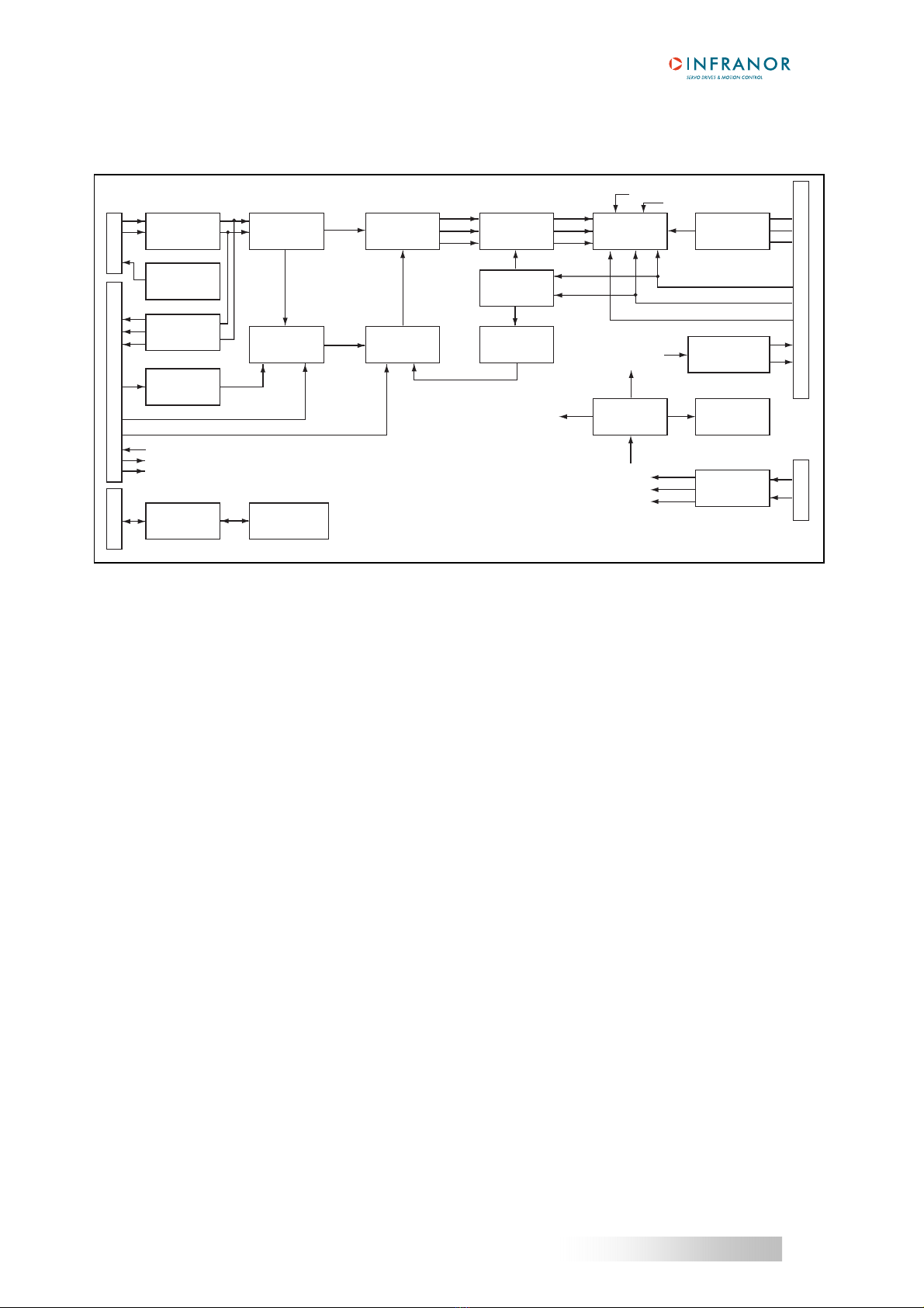
2 - BLOCK DIAGRAM
X1
X2
X5
X8
X9
A
B
Z
CV
FC/CVO
Ilim
AOK
Reset
Enable
L1
L2
L3
RB
RB
Up
Up
AOK
+24V
0V
+5V
+12V
-12V
Resolver
sensor
conversion
Sinusoidal
oscillator
Encoder
outputs
Ramp
Serial
link
Pulse
counter
Position
Speed
Speed
loop
Input command
Parameters
saving
Vector
control
Current
input
command
Current
limitation
Current
loops
Current
monitors
I2t
function
PWM
Power
stage
Enable
Fault
Rectifying
+
filtering
U motor
V motor
W motor
Fault
Energy
recuperation
Protections
processing
Reset
Display
DC/DC
converter

13
CD1-a
Chapter 2 - Specifications
3 - MAIN PROTECTIONS
3.1 - STORED PROTECTIONS
PROTECTION ERROR
DISPLAY
LED
Amplifier rated current overload (see Chapter 8, part 3.2)
I2t z
Resolver cable interruption Resolver
z
Power stage Power stage zz
Resolver converter failure R. D. C
z
Power supply undervoltage (non stored fault) Undervolt.
z
z
Motor overtemperature °C motor
zz
z
Speed following error
Following err.
z
Amplifier parameter memory EEPROM
z
zz
- Procedure execution error
- Initialization phase execution error
Busy zz
zz
24 VDC auxiliary supply out of tolerances
19 V < 24 VDC < 29 V
24 V z
z
: LED is unlit z: LED is lit.
NOTE
The power stage error includes the following faults:
- power supply overvoltage
- internal switch protection
- short-circuit between motor phases or between motor phase and earth
- amplifier overtemperature (on CD1-a-400/I only)
- fan system error
- PWM control error
- power stage supply
- braking system
The detail of the “Power stage” fault can be displayed in the Visual drive Setup software.
All these faults are stored in the amplifier except for the "Undervolt." fault.
The reset of a stored fault can be made:
- by means of the RESET function in the VISUAL DRIVE SETUP software
- via the fault RESET input (pin 13 of the X2 connector)
- by switching off the amplifier power supply.
All faults release the amplifier disabling. All faults, except for "Undervolt.", also release the opening of the AOK
relay contact.
14
CD1-a
Chapter 2 – Specifications
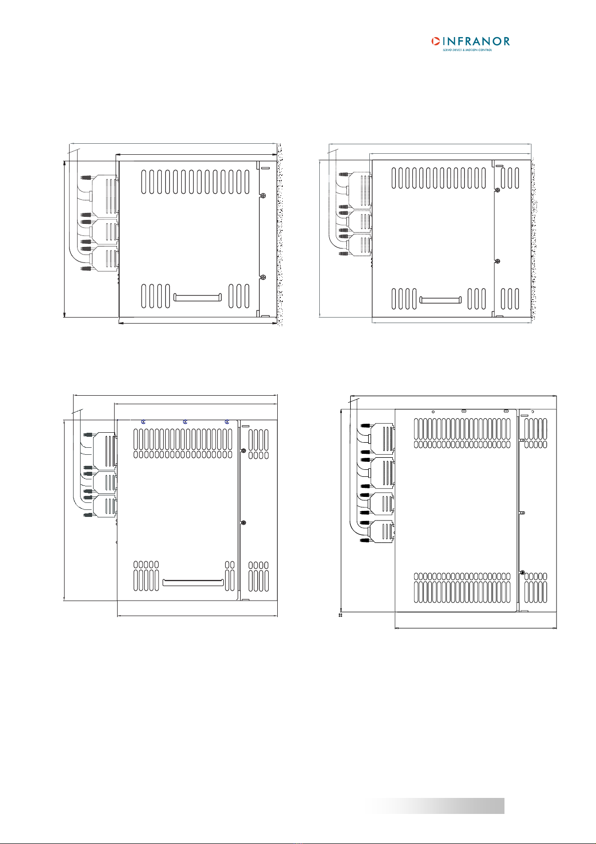
4 - DIMENSIONS
4.1 - CD1-a-230/I AMPLIFIER 4.2 - CD1-a-400/1.8 to 7.2 A AMPLIFIER
4.3 – CD1-a-400/14 A AMPLIFIER 4.4 - CD1-a-400/30 and 45 A AMPLIFIER
293
234
258
229.72
202.5
260
200
199
234
293
228
229.80
293
288
230

15
CD1-a
Chapter 2 - Specifications
4.5 - BRAKING RESISTORS dp 100/100, dp 200/100, dp 50/200 and dp 33/280
A
B
7
7
40
83
C
DIMENSIONS dp 50/200, dp 100/100 and dp 200/100 dp 33/280
Size A 157 mm 290 mm
Size B 145 mm 278 mm
Size C 52 mm 57 mm

16
CD1-a
Chapter 2 – Specifications
5 - FASTENING
VERTICAL MOUNTING IS MANDATORY
5.1 - CD1-a-230/I AMPLIFIER 5.2 - CD1-a-400/1.8 to 7.2 A AMPLIFIER
=
=
192
64.8
195 3
2 M4 screw
s
5.3 - CD1-a-400/14 A AMPLIFIER 5.4 - CD1-a-400/30 and 45 A AMPLIFIER
3.15
250
258.00
82.80 2 M4 screw
s
==
3
223
64.8
2 M4 screws
4.15
288
278.5
110.00
60.00
25.00
4 M4 screws

17
CD1-a
Chapter 2 - Specifications
6 - MULTIAXES CABINET MOUNTING
6.1 - CD1-a-230/I AMPLIFIER 6.2 - CD1-a-400/1.8 to 7.2 AMPLIFIER
80
80
70
X8 X9
GND
6.3 – CD1-a-400/14 AMPLIFIER 6.4 - CD1-a-400/30 AND 45 A AMPLIFIER
X9
RB
RB
L1
DC-
L3
W
DC+
L2
U
V
X8
0V
24V
Br+
Br-
X8
0V
24V
Br+
Br-
X9
RB
RB
L1
DC-
L3
W
DC+
L2
U
V
100
X8 X9
GND
X8 X9
70
80
80
GND
X9
X8
110.00
132.00
234,5
X9
RB
RB
DC-
L1
L2
L3
DC+
V
U
X9
RB
RB
DC-
L1
L2
L3
DC+
V
U
Ground

18
CD1-a
Chapter 3 –Inputs-Outputs
Chapter 3 - Inputs-Outputs
1 - CONNECTORS LOCATION
1.1 - AMPLIFIER CONNECTORS
CD1-a
X2
X1
X5
ERROR
DISPLAY
X8 X9
X2 Command connector
X1 Resolver connector
X5 Serial link connector
GND
X8 24 Vdc connector
X9 Power connector
2 - X1: RESOLVER CONNECTOR
Sub D 9 pins female (male connector is not supplied)
PIN FUNCTION REMARKS
1 TC (pin H sensor connector) If thermal switch connected to X1
6 Shield connection If no "360°" connection on the connector
2 TC (pin I sensor connector) If thermal switch connected to X1
7 S1 (pin C sensor connector) MAVILOR motor
3 S3 (pin D sensor connector) MAVILOR motor
8 S4 (pin B sensor connector) MAVILOR motor
4 S2 (pin A sensor connector) MAVILOR motor
9 R2 (pin F sensor connector) MAVILOR motor
5 R1 (pin E sensor connector) MAVILOR motor
For other resolver connections, see chapter 8 (Appendix), section 2.

19
CD1-a
Chapter 3 – Inputs-Outputs
3 – X2: COMMAND CONNECTOR, LOGIC INPUTS-OUTPUTS AND ENCODER
Sub D 25 pins male (female connector is not supplied)
Pin Function I / O REMARKS
1 FC+: Limit switch + I Positive logic, optocoupled input, galvanic insulation
14 FC-: Limit switch - I Positive logic, optocoupled input, galvanic insulation
24 Ref. inputs I Supply reference of the galvanic insulated logic inputs
20 ENABLE I Positive logic, optocoupled input, galvanic insulation
23 Ref. inputs I Supply reference of the galvanic insulated logic inputs
2 Current command CI I Positive logic, optocoupled input, galvanic insulation
10 CV0 Zero speed input
command
I Positive logic, optocoupled input, galvanic insulation
25 GND I GND reference of the earthed amplifier
13 RESET I Positive logic, optocoupled input, galvanic insulation
Inhibition of the faults memory stored in the amplifier
12 Ref. inputs (0 Volt) I Supply reference of the galvanic insulated logic inputs.
17 CV+ Input command CV + I ± 10 V speed input command for max. speed
16 CV- Input command CV - I or ± 10 V current input command for Imax with "CI" input active
15 GND I GND reference of the earthed amplifier
3 I limit current limitation I Analog input for external max. current limitation
0 to 10 V for 100 % to 0 % of Imax
11 Reserved input I Do not use (to be used by INFRANOR only)
18, 19 AOK: amplifier ready O Relay contact: closed if amplifier OK, open if fault.
Protection against overvoltages by bidirectional TRANSIL
Pmax = 10 W with Umax = 50 V or Imax = 100 mA
21 + 12 Volts O Output impedance: 47 Ohms. Max. 50 mA available
22 - 12 Volts O Output impedance: 47 Ohms. Max. 50 mA available
4 Z/ O Differential output of Z/ encoder marker pulse (max. 5 V, 20 mA)
5 Z O Differential output of Z encoder marker pulse (max. 5 V, 20 mA)
6 A/ O Differential output of encoder A/ channel (max. 5 V, 20 mA)
7 A O Differential output of encoder A channel (max. 5 V, 20 mA)
8 B/ O Differential output of encoder B/ channel (max. 5 V, 20 mA)
9 B O Differential output of encoder B channel (max. 5 V, 20 mA)

20
CD1-a
Chapter 3 –Inputs-Outputs
3.1 - SPECIFICATION OF THE ANALOG INPUTS: CV+, CV-, Ilim
4 K
4 K
-
-
+
+
10 nF
10 nF
10 nF
CV+
CV-
X2/17
X2/16
X2/15
ILIM
X2/3
X2/25
10K10K
10K 10K
4 K
10K 10K
GND
GND
3.2 - SPECIFICATION OF THE LOGIC OPTOCOUPLED INPUTS: ENABLE, FCP, FCN, RESET, CVO, CI
The input voltage corresponding to level 1 is between 18 V and 30V.
3.3 - SPECIFICATION OF THE "AOK" RELAY OUTPUT
AOK
AOK/
X2/18
X2/19
+12 V
Bidirectional
53 V
TRANSIL
Relay contact open if any fault except for the "Undervolt." fault.
Pmax = 10 W with Umax = 50 V and Imax = 100 mA
3.4 - SPECIFICATION OF THE ENCODER OUTPUTS
Recommended receiver: 26LS32
Logic input
100 KΩ
0 V
5 V
8.2 KΩ100 nF 10 KΩ
X2 - 5-7-9
X2 - 4-6-8
CI
26LS31
+5V
Table of contents
Other Infranor DC Drive manuals


Popular DC Drive manuals by other brands


Honeywell
Honeywell 3G SmartVFD HVFD3D3A0015 Installation and user guide

Grundig
Grundig GD-LD-AC2812DC-IR instruction manual

Invertek
Invertek Optidrive Eco ODV-3-220043-1F12-TN user guide

DeVilbiss
DeVilbiss QS-5012 Service bulletin

Bosch
Bosch Servodyn-D manual

Siemens
Siemens 3VF 9 423-1 0 Series operating instructions


