Infranor XtrapulsCD1-EM-400/70 User manual

XtrapulsCD1-EM-400/70-90
Drives for
AC servo motors
in embedded
applications

2
CD1-EM-400/70-90 servo drive
WARNING
This is a general manual describing a series of servo drives having output capability suitable for driving AC
brushless sinusoidal servo motors.
Instructions for storage, use after storage, commissioning as well as all technical details require the
MANDATORY reading of the manual before getting the drives operational.
Maintenance procedures should be attempted only by highly skilled technicians having good knowledge
of electronics and servo systems with variable speed (EN 60204-1 standard) and using proper test
equipment.
The conformity with the standards and the "CE" approval is only valid if the items are installed according to the
recommendations of the drive manuals. Connections are the user's responsibility if recommendations and
drawings requirements are not met.
INFRANOR does not assume any responsibility for any physical or material damage due to improper handling or
wrong descriptions of the ordered items.
Any intervention on the items, which is not specified in the manual, will immediately cancel the warranty.
Infranor reserves the right to change any information contained in this manual without notice.
© INFRANOR, February 2013. All rights reserved.
Issue: 2.4
!
Any contact with electrical parts, even after power down, may involve physical damage.
Wait for at least 5 minutes after power down before handling the drives (a residual voltage of several
hundreds of volts may remain during a few minutes).
ESD INFORMATION (ElectroStatic Discharge)
INFRANOR drives are conceived to be best protected against electrostatic discharges. However,
some components are particularly sensitive and may be damaged if the drives are not properly stored
and handled.
STORAGE
- The drives must be stored in their original package.
- When taken out of their package, they must be stored positioned on one of their flat metal
surfaces and on a dissipating or electrostatically neutral support.
- Avoid any contact between the drive connectors and material with electrostatic potential
(plastic film, polyester, carpet…).
HANDLING
- If no protection equipment is available (dissipating shoes or bracelets), the drives must be
handled via their metal housing.
-
Never get in contact with the connectors.
ELIMINATION
In order to comply with the 2002/96/EC directive of the European Parliament and of the Council of
27 January 2003 on waste electrical and electronic equipment (WEEE), all INFRANOR devices
have got a sticker symbolizing a crossed-out wheel dustbin as shown in Appendix IV of
the 2002/96/EC Directive.
This symbol indicates that INFRANOR devices must be eliminated by selective disposal and not
with standard waste.

3
CD1-EM-400/70-90 servo drive
Content
Content
Page
CONTENT ............................................................................................................................................... 3
CHAPTER 1 – GENERAL DESCRIPTION............................................................................................. 4
1.1 -INTRODUCTION.......................................................................................................................... 4
1.2 -OTHER DOCUMENTS REQUIRED FOR THE COMMISSIONING ............................................. 4
1.3 -ORDERING CODES .................................................................................................................... 5
CHAPTER 2 – SPECIFICATIONS.......................................................................................................... 6
CHAPTER 3 – MECHANICAL DATA..................................................................................................... 8
3.1 -DRIVE DIMENSIONS................................................................................................................... 8
3.2 -CABINET LAYOUT....................................................................................................................... 9
CHAPTER 4 - CONNECTIONS ............................................................................................................ 10
4.1 -DRIVE CONNECTION ............................................................................................................... 10
4.2 -MOTOR CONNECTION............................................................................................................. 10
CHAPTER 5 – SETUP & OPERATION................................................................................................ 11
CHAPTER 6 - FAN SPECIFICITIES..................................................................................................... 12
6.1 -FAN SPEED CONTROL............................................................................................................. 12
6.2 -FAN REPLACEMENT PROCEDURE ........................................................................................ 13

4
Chapter 1 - General description
CD1-EM-400/70-90 servo drive
Chapter 1 – General description
1.1 - INTRODUCTION
XtrapulsCD1-EM-400/70-90 all-digital drives with sinusoidal PWM control are servo drives that provide the control
of servo motors equipped with a position sensor. They can be configured for various position sensor types
(resolver, incremental encoder, absolute encoder). The appropriate position sensor configuration is selectable by
software and saved in the drive.
XtrapulsCD1-EM-400/70-90 drives power supply is 400 to 480 VAC three-phase mains. A soft start system of the
power supply allows to limit the inrush current at power on. The maximum output current is available during 1
second. The drive rated output current is the current value available for permanent operation.
The EM version of the CD1-400/70-90 drive is dedicated to embedded applications. This version differs from the
standard CD1-400/70-90 regarding the rugged mechanical housing and the modified mechanical mounting.
- The push through mounting allows to push the heatsink and the air forced cooling outside the electric cabinet.
- The flat fastening of the drive according to the larger surface area allows to improve its rigidity to shocks and
vibrations.
The CD1a-EM-400/70-90 version is dedicated to applications with ± 10 V analog input command. The CD1k-EM-
400/70-90 version is to be used in applications with input command via CAN fieldbus and is based on CANopen
DSP402 protocol. The CD1pm-EM-400/70-90 version is to be used in stand-alone positioning applications or with
input command via PROFIBUS fieldbus.
1.2 - OTHER DOCUMENTS REQUIRED FOR THE COMMISSIONING
Only the information specific to the EM-400/70-90 version of the XtrapulsCD1 drives can be found in this
document. Please refer to the standard XtrapulsCD1 range manuals for the complete information:
CD1-a servo drive manual,
CD1-k Installation Guide,
CD1-k User Guide,
CANopen Communication Protocol for CD1-k drives,
CD1-pm Installation Guide,
CD1-pm User Guide,
PROFIBUS Communication Protocol for CD1pm drives.
5
Chapter 1 - General description
CD1-EM-400/70-90 servo drive
1.3 - ORDERING CODES
1.3.1 – DRIVE ORDERING CODE
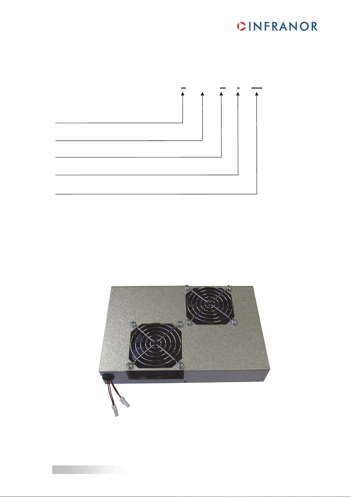
1.3.2 - FAN REPLACEMENT KIT
FAN CD1 - EM - 90
The fan replacement kit consists in the complete fan carter, equipped with fans, grids and connectors:
XTRAPULS CD1 - x - EM - U / I - CT
a: +/- 10 V analog interface
k: CANopen interface
pm: Profibus interface
EM: Embedded applications
U: 400: 400/480 Vac voltage rating
I: 70 / 90 Arms current ratings
CT: "Cogging torque compensation" option

6
Chapter 2 - Specifications
CD1-EM-400/70-90 servo drive
Chapter 2 – Specifications
Operating power supply voltage - 400 to 480 VAC + 10 %/- 15 % 3~ mains, TN or
TT system with earthed neutral point, 50 - 60 Hz
(Phase/Ground voltage must be balanced)
- 140 to 700 Vdc DC link power supply
Auxiliary logic and motor brake supply voltage 24 Vdc +/-15 % - 320 mA without brake
Motor RMS output voltage 95 % Udc/√2
Integrated braking system External resistor: 16.5 Ω/560 W (EF 400)
Output current ratings
Model
Max. output
current (Arms)
for 1 sec.
+/- 5 %
Rated
output
current
(Arms)
Power
losses
(W)
Rated input
current (Arms)
(400 VAC,
60 Hz)
Max. protection
fuses for line circuit
A60Q40 listed
Short-
circuit
power of
the mains
UL listed
CD1-EM-400/70 70 35 650 35 40 A 5 kA
No
CD1-EM-400/90 90 35 650 35 40 A 5 kA
No
Mains filter on power supply - Integrated EMC capacitors
- External common mode choke
- Recommended filter: F-400-70-90
Standard undervoltage threshold 140 Vdc
Standard braking threshold 790 Vdc
Standard overvoltage threshold 910 Vdc
Common mode filter on auxiliary supply Integrated in the drive
Common mode filter on motor brake supply Integrated in the drive
Motor brake control Open collector output protected against load short-circuit.
2 A maximum with 24 Vdc.
Compliance with the standards: CE certification.
360° shield connection, equipotentiality according
to the wiring rules and mains filter F-400-70/90.
EMC standards:
- immunity: EN 61000.4-2-3-4-5
- conducted and radiated disturbances: EN 55011, Group 1,
C3 category
Electrical standards for industrial machines:
- EN 60204-1: insulator 1500 Vac / 1 mn
leakage current > 30 mA (EMI filters).
Temperature
Storage: -20° C to +70° C
Operation: +5° C to +60° C
Altitude 1000 m
Moisture < 50% at 40° C and < 90% at 20° C: EN 60204-1 standard
Condensation prohibited (storage and operation)
Cooling Forced air (fan integrated in the drive).
Environment - Electronic part is IP20: it must be mounted in a housing
protecting the drive from conducting dust and condensation
(pollution degree 2 environment).
- Heatsink part is IP64: it is protected against dust and
splashed water. Periodic replacement is necessary,
according to the environment

7Chapter 2 -Specifications
CD1-EM-400/70-90 servo drive
Mounting location Closed cabinet without any conducting and/or corroding
agents and according to the environment conditions
requirements
Condensation prohibited inside the cabinet
Weight Approximately 8 kg

8Chapter 3 – Mechanical data
CD1-EM-400/70-90 servo drive
Chapter 3 – Mechanical data
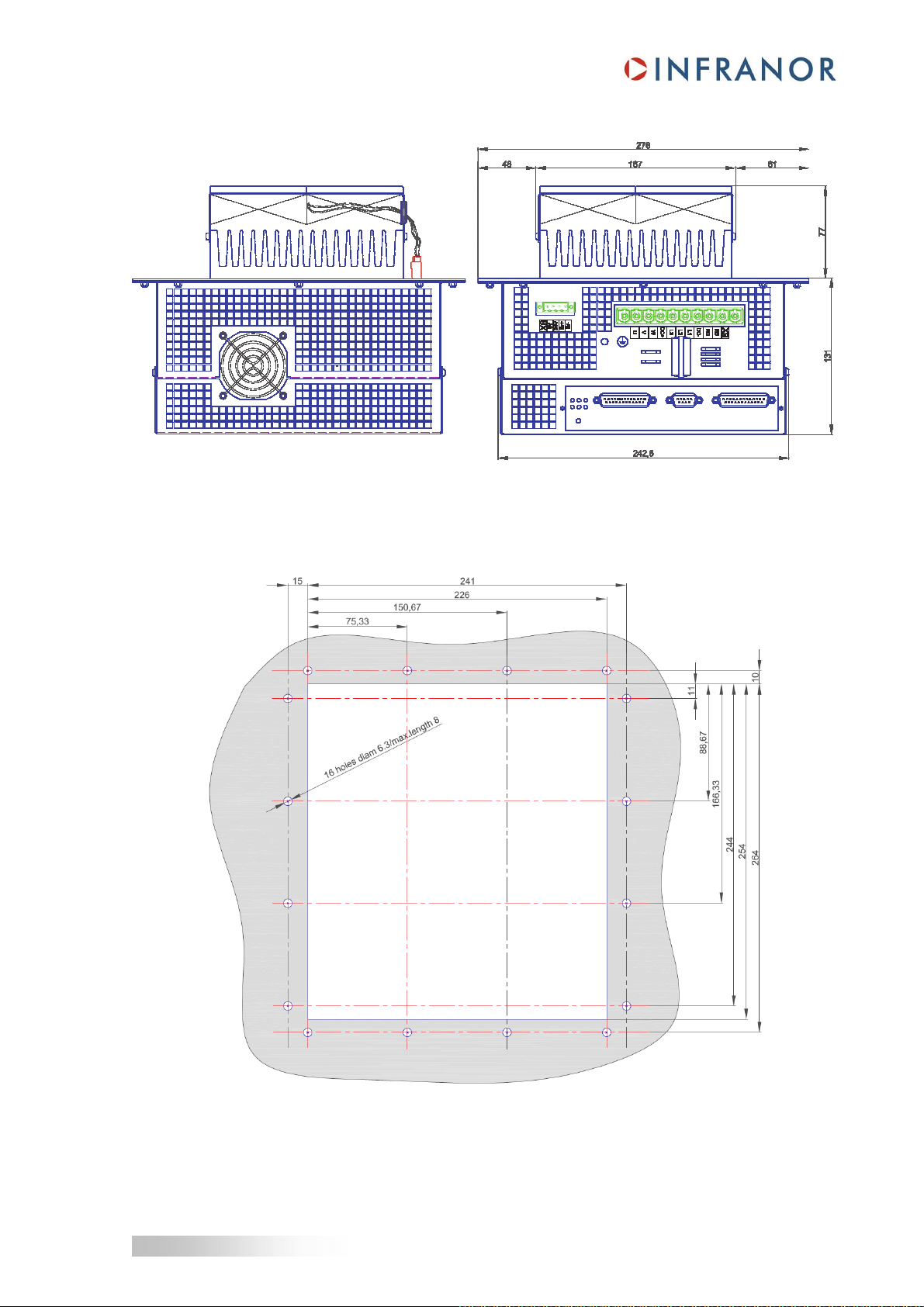
3.1 - DRIVE DIMENSIONS
FRONT VIEW
'A' VIEW 'B' VIEW
9
Chapter 3 – Mechanical data
CD1-EM-400/70-90 servo drive
'C' VIEW 'D' VIEW
3.2 - CABINET LAYOUT
It is highly recommended to place a silicone seal around the cut-out in order to avoid any entry of dust or humidity
inside the cabinet.
Recommended silicone reference: CAF530
Manufacturer: BLUESTAR SILICONES

10
CD1-EM-400/70-90 servo drive
Chapter 4 – Connections
Chapter 4 - Connections
4.1 - DRIVE CONNECTION
For complete information about the XtrapulsCD1-a, CD1-k or CD1-pm servo drive connections, please see the
pertaining installation manuals.
4.2 - MOTOR CONNECTION
Take great care about the motor connections:
- Connect the shield on the drive just before the ferrite core, preferably with a metallic collar,
- The motor phases run through the ferrite core to be connected on U, V and W outputs.
- The ground wire runs outside the ferrite core to be connected on the ground screw.
- The brake wires run outside the ferrite core to be connected on the Br+ and Br- outputs.

11
Chapter 5 – Setup & Operation
CD1-EM-400/70-90 servo drive
Chapter 5 – Setup & Operation
The Visual Drive Setup software is PC compliant under Windows® 1and allows an easy parameter setting of the
XtrapulsCD1 drive range. Please see our website www.infranor.com for downloading this software.
For information about the XtrapulsCD1-a, CD1-k or CD1-pm servo drive setup, commissioning and operation,
please see the appropriate manuals.
1Windows®is a registered trade mark of MICROSOFT®CORPORATION

12
CD1-EM-400/70-90 servo drive
Chapter 6 – Fan specificities
Chapter 6 - Fan specificities
6.1- FAN SPEED CONTROL
In order to increase the lifetime of fans, their rotation speed is controlled according to the motor
current.
A detailed description is available in the following diagram:
IMOTOR
(A)
t (s)
Fans
speed
5%.IMA
X
15%.IMA
X
100%
60%
100
t (s)
100 100
13
CD1-EM-400/70-90 servo drive
Chapter 6 - Fan specificities
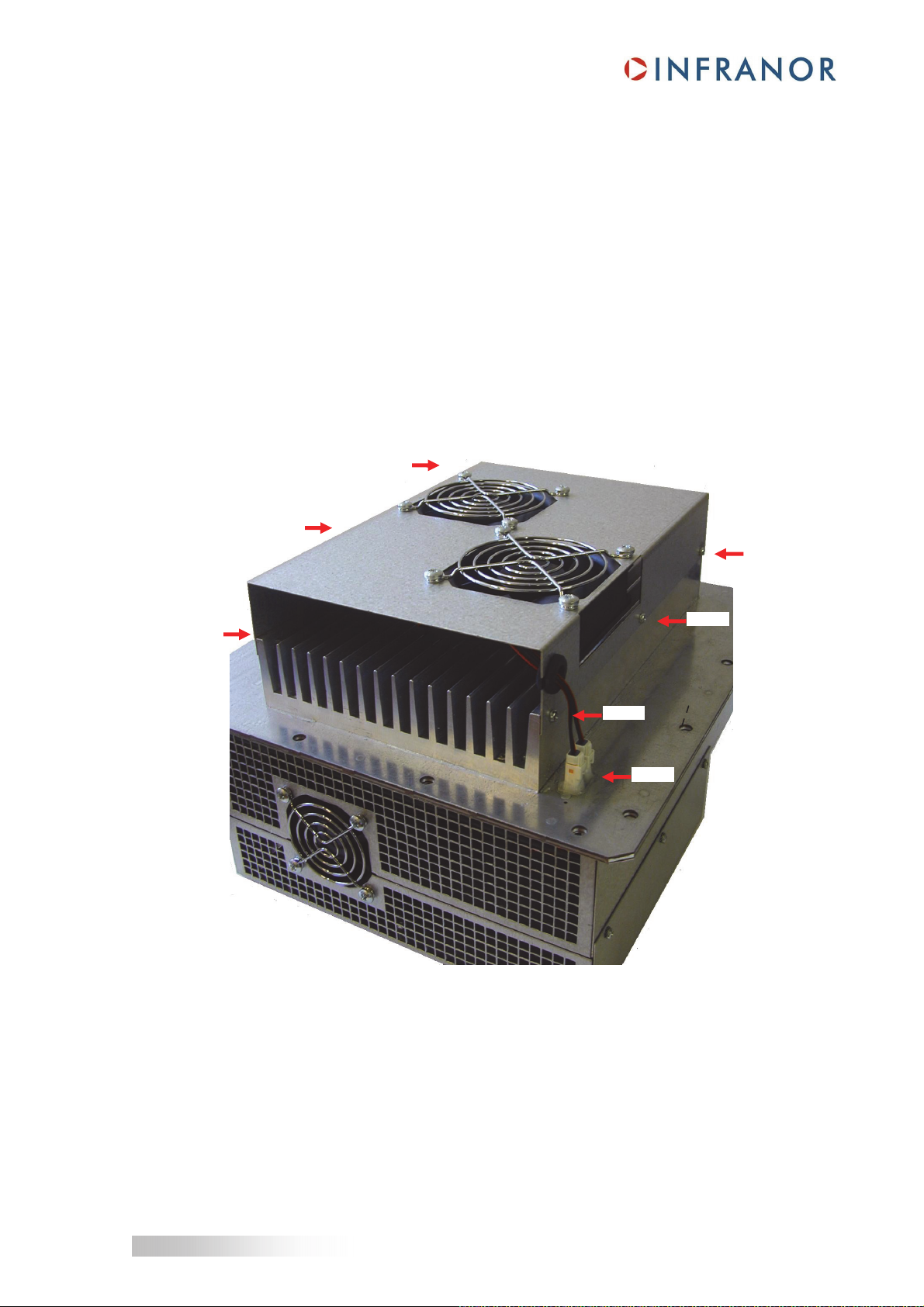
6.2 - FAN REPLACEMENT PROCEDURE
The drive is provided with two fans external to the cabinet.
These fans are developed to work in hard conditions and have a life expectancy of:
50'000 hours at 25°C, 65 % humidity, 90 % CL.
Although the lifetime greatly depends on the real environment where the drive is working, it is advised to replace
fans at least every 3 years.
To replace fans, proceed as follows:
1. Disable the drive
2. Switch off the power supply (power & auxiliary supplies) of the drive
3. Disconnect both fans
4. Remove the 6 screws fixing the fan carter
5. Mount the new fan carter with the 6 screws
6. Connect the two fans
7. Restart the drive.
4 & 5
4 & 5
4 & 5
4 & 5
4 & 5
4 & 5
3 & 6
This manual suits for next models
1
Table of contents
Other Infranor DC Drive manuals


Popular DC Drive manuals by other brands

Danfoss
Danfoss VLT FC 103 Design guide

Danfoss
Danfoss VLT AutomationDrive FC 360 operating guide

Addonics Technologies
Addonics Technologies AD25MSD user guide

Fuji Electric
Fuji Electric Frenic lift Reference manual

Allen-Bradley
Allen-Bradley PowerFlex 70 installation instructions

ABB
ABB ACS880-07 user manual


