Ingenieurbüro Mencke & Tegtmeyer Si-RS485TC-T-MT User manual
Ingenieurbüro Mencke & Tegtmeyer GmbH • Schwarzer Weg 43A • 31789 Hameln • Germany • www.ib-mut.de
Types
Type
Voltage supply
Measuring range irradiance
Protocol
All sensors
12 to 28 VDC
0 to 1500 W/m2
MB: Modbus (RTU)
MT: M&T protocol
CANopen (CiA437)
Type
Measuring
temperature solar cell
Note
Si-RS485TC-T-MT
Si-RS485TC-T-MB
-40 to +90°C
./.
Si-CANopenTC-T
-25 to 75°C
./.
Si-RS485TC-2T-MT
Si-RS485TC-2T-MB
-40 to +90°C
Hard-wired external ambient temperature sensor
(-40 to 90°C)
Si-RS485TC-T-Tm-MT
Si-RS485TC-T-Tm -MB
-40 to +90°C
Hard-wired external module temperature sensor
(-40 to 90°C)
Si-RS485TC-2T-v-MT
Si-RS485TC-2T-v-MB
-40 to +90°C
Female connectors for optional external temperature sensor
(-40 to 90°C) and wind speed sensor (0 to 80 m/s)
Si-CANopenTC-2T
-25 to 75°C
Hard-wired external ambient temperature sensor (-25 to 75°C)
Si-CANopenTC-2T-v
-25 to 75°C
Female connectors for optional external temperature sensor
(-25 to 75°C) and wind speed sensor (0 to 80 m/s)
Measurement uncertainty over all,
according to GUM (Guide to the Expression of Uncertainty in Measurement), k = 2
Irradiance
±5 W/m²± 2.5 % of MV valid perpendicular incidence of the light, spectrum AM 1.5
Cell temperature
1.0 K Range -35 to 80°C
User information
The guarantee is for 1 year from the date of the invoice for the intended use. M&T does not accept any liability
for possible losses or damage due to the incorrect usage of the sensor. Liability for consequential damages is
excluded.
Special note: The housing for the Si sensors is not allowed to be opened by the installer or user because, as a
consequence, the housing will no longer be sealed after it is closed. If the housing is opened, the
manufacturer's warranty will be rendered void.
Maintenance
Scope of the regularly check (at least every 2 years): Cleaning of solar cell, external damage, mechanical
fastening, cable laying and any damage to the cable.
In the report IEA-PVPS T13-03:2014 "Analytical Monitoring of Grid-connected Photovoltaic Systems" an
interval of 1 to 2 weeks is recommended.
Should damage be found that degrades the function or safety, the sensor is to be replaced.
A recalibration is recommended at least every 3 years.
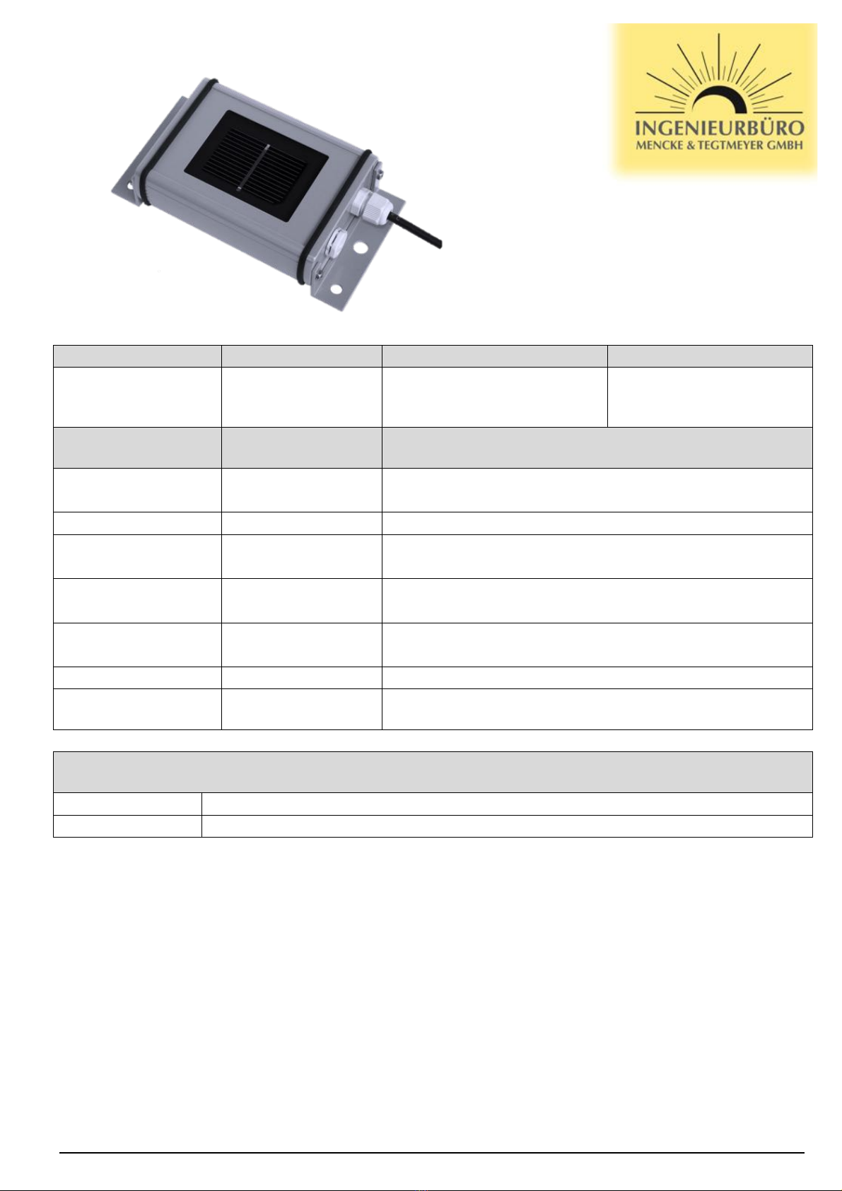
Quick Reference Guide
digital Silicon Irradiance Sensor
Main data
Irradiance measurement: up to 1500 W/m2
Cell temperature measurement: RS485: -40 to +90°C
CANopen: -25 to +75°C
Working temperature: -35 to 80°C
Weight: appr. 0.4 kg
Ing.-Büro Mencke & Tegtmeyer GmbH, Hameln Quick reference guide digital Silicon Irradiance Sensor
Page 2 of 4 Date: September 2017 All rights reserved
Si sensors that are used for monitoring PV installations must be installed with the same alignment
and inclination as the PV generator. The mounting location should be free of shading as far as
possible.
To facilitate maintenance and cleaning of the Si sensor, the Si sensor should be mounted in an easily
accessible place (e.g. near roof windows or skylights).
The mounting location at a PV generator must be selected such that snow cannot jeopardise the Si
sensor as it slides off. For this reason do not mount along the drip edge on the PV generator.
The connecting cable should always be laid separated from, e.g. main DC cables or AC cables.
The connecting cable is to be laid so it is fixed.
The minimum bending radius of 15 x cable diameter (ø approx. 5 mm) is to be observed.
The voltage drop at the cable has to be considered when calculating the maximum cable length.
The pressure equalisation element must not be damaged.
The cable gland is not allowed to be undone or tightened by the user.
It is not necessary for the installer or user to open the Si sensor. If the housing is nevertheless
opened, no liability for the sealing can be accepted.
The surge protection concept must be adapted to the specific local situation. This means, for
instance, that the measuring cables must be equipped with a separate surge arrester at the entry to a
building.
The sensor must be integrated into the lightning protection concept.
The sensors are designed for safety extra-low voltage (SELV) operation.
Reversing the polarity or mixing up the connections on the Si sensor may cause irreversible damage
to the sensor.
The cable shield is to be connected to PE during installation.
The installation and assembly of electrical equipment must be carried out by electrically qualified
persons.
The sensor may not be used with equipment whose direct or indirect purpose is to prevent human
death or injury, or whose operation poses a risk to humans, animals or property.
Mortal danger due to electrical power
On the connection of the Si sensor to an inverter, dangerous voltages are present on the inverter
(disconnection, secure against switching, follow inverter manual).
Should it be necessary to clean the Si sensor, a soft cotton cloth, water and a mild cleaning agent
can be used for this purpose.
A terminating resistor is usually not required for the RS485 sensors (MB and MT).
In principle a terminating resistor of 120 Ωat both ends of the CANopen bus is required for the
CANopen sensors.
Wire colour
Wire colour
All RS485 sensors
All CANopen sensors
Orange
RS485 Data- / B
CAN high
Brown
RS485 Data+ / A
CAN low
Black
Supply (negative)
Supply (negative)
Red
Supply (positive)
Supply (positive)
Black (thick)
Shield
Shield
Items supplied:
-Si sensor incl. pre-assembled connecting cable or suitable male connector
-Data sheet
-Calibration record
Ing.-Büro Mencke & Tegtmeyer GmbH, Hameln Quick reference guide digital Silicon Irradiance Sensor
Errors and omission excepted Date: September 2017 Page 3 of 4
A
B
C
D
E
FF
E
D
C
B
A
Drawing No.
Page:
12345678
A
B
C
D
E
FF
E
D
C
B
A
Drawing name:
12345678
Scale: none
A
B
C
D
E
FF
E
D
C
B
A
Projekt:
Si - Series
of 1 pages
1
12345678
Silicon Irradiance Sensor
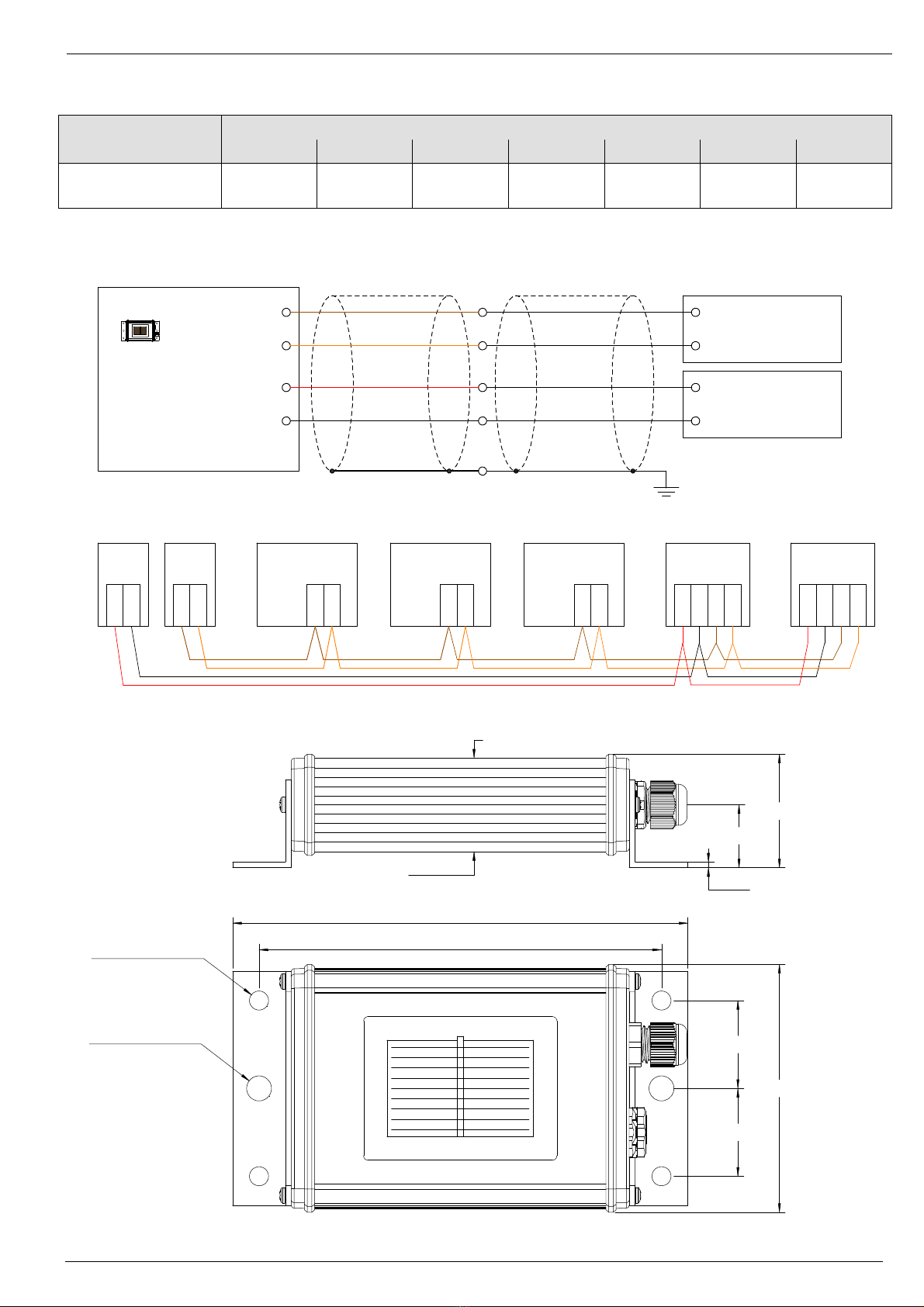
155±1.0 mm
137±1.0 mm
85 mm
30 mm
30 mm
39 mm
2 mm
85 mm
Ø 8.5 mm - 2x
Ø 6.5 mm - 4x
32 mm
22 mm
Maximum additional cable length of Si sensors with 3 m connection cable
at voltage supply of 24 VDC / 12 VDC
Sensor type
Cable diameter
0,14 mm2
0,25 mm2
0,34 mm2
0,5 mm2
0,75 mm2
1,0 mm2
1,5 mm2
Si-RS485TC-XXX
300 m /
50 m
600 m /
100m
800 m /
150m
1.000 m /
200 m
1.000 m /
300m
1.000 m /
400m
1.000 m /
650m
Wiring diagram of digital Si sensors
Bus topology
Dimension
Data +
Data -
Plus
Minus
Data +
Power Supply Plus
Power Supply Minus
Data -
Data +
Data -
Data +
Data -
Data +
Data -
Data +
Data -
Types
Si-RS485TC-X
Inverter
Datal-
ogger Inverter Si-Sensor
RS 485
Inverter
PE
Datalogger
Power Supply
Cable Shield
Optional
Te mp e r at u r e
Irradiance
Power Supply
Plus
Power Supply
Minus
Types
Si-01TC(-T)
Si-13TC(-T)
Si-420TC(-T)
SiS-01TC(-T)
SiS-13TC(-T)
SiS-420TC(-T)
Si(S)-Sensor
brown
orange
red
black
black (thick)
AIN 1+
AIN 2+
AIN 1-
AIN 2-
V+
V-
Data +
Data-
Plus
Minus
Power-
Supply
RS 485 RS 485 RS 485 RS 485
Cable Shield
PE
Cable Shield
brown
orange
red
black
black (thick)
Cable Shield
Datalogger
Power Supply
V+
V-
Si-Sensor
Plus
Minus
Data +
Data -
Si-Sensor
RS 485
Data +
Power Supply Plus
Power Supply Minus
Data -
Types
SiS-RS485TC-X
Data +
Data-
PE
Cable Shield
brown
orange
red
black
yellow
Cable Shield
Datalogger
Power Supply
V+
V-
SiS-Sensor
Data +
Data -
Plus
Minus
Data +
Power Supply Plus
Power Supply Minus
Data -
Data +
Data -
Data +
Data -
Data +
Data -
Data +
Data -
Types
Si-RS485TC-X
Inverter
Data-
logger Inverter Si-Sensor
RS 485
Inverter
PE
Datalogger
Power Supply
Cable Shield
Optional
Te mp e r at u r e
Irradiance
Power Supply
Plus
Power Supply
Minus
Types
Si-01TC(-T)
Si-13TC(-T)
Si-420TC(-T)
SiS-01TC(-T)
SiS-13TC(-T)
SiS-420TC(-T)
Si(S)-Sensor
brown
orange
red
black
black (thick)
AIN 1+
AIN 2+
AIN 1-
AIN 2-
V+
V-
Data +
Data-
Plus
Minus
Power-
Supply
RS 485 RS 485 RS 485 RS 485
Cable Shield
PE
Cable Shield
brown
orange
red
black
black (thick)
Cable Shield
Datalogger
Power Supply
V+
V-
Si-Sensor
Plus
Minus
Data +
Data -
Si-Sensor
RS 485
Data +
Power Supply Plus
Power Supply Minus
Data -
Types
SiS-RS485TC-X
Data +
Data-
PE
Cable Shield
brown
orange
red
black
yellow
Cable Shield
Datalogger
Power Supply
V+
V-
SiS-Sensor

Ing.-Büro Mencke & Tegtmeyer GmbH, Hameln Quick reference guide digital Silicon Irradiance Sensor
Page 4 of 4 Date: September 2017 All rights reserved
Mounting instruction
Technical data
General data
Solar cell
Monocrystalline silicon; 50 mm x 33 mm
Housing Material
Powder-coated aluminium
Dimension / Weight
155 mm x 85 mm x 39 mm / appr. 350 to 470 g
Degree of protection
IP 65
Operating temperature
-35 to +80°C
Supply voltage
24 VDC (12 ... 28 VDC)
Current consumption
Typical 35 mA at 24 VDC
Sensor cable
LiYC11Y 4x0.14mm2UL20233; length typical 3m
Maximum cable length for RS485
1000 m
Maximum cable length for CANopen
200 m (at 125 kBaud)
Customs tariffs number
85 41 40 90
Protocol
Settings (standard)
Note
Modbus (RTU)
Address: 1
Transmission rate: 9600 baud
Format: 8N1
Address can be set (e.g. using software "Si
Modbus Configurator")
Max. transmission rate 38400 baud
MT
Address: last two digits of serial number
Transmission rate: 9600 baud
Format: 8N1
Cannot be changed
CANopen
Transmission rate: 125 kbaud
Protocol to CiA 437
Max. transmission rate 250 kbaud
Note for configuration with software "Si Modbus Configurator“: Required are a computer, a voltage supply
and an USB to RS485 interface converter. We recommend as a converter the ICPCON I-7561 or DIGITUS,
type DA-70157.
Please read also the installation and operating instruction (newest version on www.ib-mut.de).
See technical data for
maximum cable length
Fastening with at least
one screw per wall
bracket
Ø 6.5 mm
Ø 8.5 mm
Ø 6.5 mm
Not allowed for
Si-RS485TC-2T-v
and
Si-RS485TC-2T
This manual suits for next models
10
Other Ingenieurbüro Mencke & Tegtmeyer Accessories manuals

Popular Accessories manuals by other brands

Pil Sensoren
Pil Sensoren P41-200-I-CM12 quick start guide

Samsung
Samsung SmartThings STS-PRS-250 quick start guide

CyberPower
CyberPower CP2500NLS Product guide

Baumer
Baumer OADM 20U5440/S14C manual

Tronic
Tronic QI TPBQ 10000 A1 Operation and safety notes

Invacare
Invacare Personal Seat VF Installation and operating instructions


