manuals.online logo
Brands
  1. Home
  2. •
  3. Brands
  4. •
  5. Ingersoll-Rand
  6. •
  7. Impact Driver
  8. •
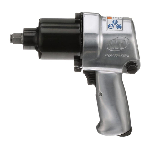
  9. Ingersoll-Rand 588A1 Setup guide

Ingersoll-Rand 588A1 Setup guide

16600983
Edition 1
October 2007
Save These Instructions
Air Impact Wrench
588A1
Maintenance Information
2 16600983_ed1
WARNING
Always wear eye protection when operating or performing maintenance on this tool.
Always turn o the air supply and disconnect the air supply hose before installing, removing or adjusting any accessory on this tool or
before performing any maintenance on this tool.
Note: When reading the instructions, refer to exploded diagrams in parts Information Manuals when applicable (see under Related Documentation
for form numbers).
Disassembly
General Instructions
Do not disassemble the tool any further than necessary to replace
or repair damaged parts.
Whenever grasping a tool or part in a vise, always use leather-
covered or copper-covered vise jaws to protect the surface of
the part and help prevent distortion. This is particularly true of
threaded members and housings.
Do not remove any part which is a press t in or on a subassembly
unless the removal of that part is necessary for repairs or
replacement.
Do not disassemble the tool unless you have a complete set of
new gaskets and O-rings for replacement.
Disassembly of the Impact Wrench
WARNING
Never attempt to disassemble a Model 588A1 or 588A1-EU
Impact Wrench without a hoist, block and tackle, or other lifting
device. The complete Impact Wrench and its major assemblies
are too heavy to be manually handled. Follow the recommended
procedure for disassembly below.
Suspend the Impact Wrench by the Vertical Hanger (36) in the
Back Head (22) and place a large socket on solid, level footing
beneath it.
Lower the tool, engaging the square driver in the socket drive
hole. As a safety measure, leave the hoist hook attached to the
Eyebolt so that the Tool cannot tip over.
Remove the Hammer Case Long Bolts (11) and Hammer Case
Short Bolts.
Slowly lift the Motor Housing (1) with assembled parts from
the Gear Case (50). 11 the Motor Housing and Gear Case fail to
separate after raising the Motor Housing about 1/2”(12 mm),
lightly strike the Gear Case with a soft hammer to jar it loose.
1.
2.
3.
4.
1.
2.
3.
4.
Attach the hoist sling to the planet gear frame assembly and lift
the Gear Case with assembled parts from the Hammer Case (82).
If the Gear Case and Hammer Case fail to separate after raising
the Gear Case about 1/2” (12 mm), lightly strike the hammer case
bosses a few downward blows with a soft hammer.
Remove the Backhead Long Cap Screws (25), Backhead Short Cap
Screws (26) and Backhead (22). This will give access to the motor.
Disassembly of the Impact Mechanism
Before removing the Ball Cam (75) from the Hammer (77), clean
the grease from the Hammer, Cam Balls (74) and Ball Cam.
Stand the Hammer, jaw end down, on an arbor press table and
press on the face of the Ball Cam, telescoping it into the hammer
bore against the compression of the Hammer Spring (76) until a
Cam Ball drops from each of the two holes in the hammer wall.
Slowly ease the pressure on the Ball Cam and withdraw the Ball
Cam from the Hammer.
Disassembly of the Motor
Grasp the splined rotor hub in copper-covered vise jaws and
unscrew the Governor Assembly from the Rotor (15).
NOTICE
This is left-hand thread; turn clockwise to remove.
2. Grasp the Cylinder (19) in one hand; never clamp it in a vise.
Insert a 5/16” (7 mm) diameter rod about 6” (150 mm) long into
the rotor bore and drive on the rod until the rear rotor hub is
driven out of the Rear Rotor Bearing (21), freeing the Rear End
Plate (20), Cylinder and Vanes (18).
3. Support the Front End Plate (14) as close to the Rotor as possible
and press on the pinion face to remove the Front Rotor
Bearing (13) from the rotor hub.
5.
6.
1.
2.
3.
1.
Assembly
General Instructions
Always press on the inner ring of a ball-type bearing when
installing the bearing on a shaft.
Always press on the outer ring of a ball-type bearing when
pressing the bearing into a bearing recess.
Whenever grasping a tool or part in a vise, always use leather-
covered or copper-covered vise jaws. Take extra care with
threaded parts and housings.
Always clean every part and wipe every part with a thin lm of oil
before installation.
Apply a lm of O-ring lubricant to all O-rings before nal
assembly.
Assembly of the Motor
Slip the Front End Plate (14), crescent grooved side rst, onto the
rotor front hub.
Place the Front Rotor Bearing (13), shielded side rst, over the
hub.
Slide a sleeve that will contact only the bearing inner ring over
the hub and press the Bearing onto the rotor hub until only
running clearance remains between the faces of the End Plate
and Rotor (15).
1.
2.
3.
4.
5.
1.
2.
3.
Grasp the splined hub in copper-covered vise jaws, positioning
the Rotor upright. Place a Vane (18) in each vane slot in the Rotor;
then place the Cylinder (19) over the Rotor and onto the End
Plate.
NOTICE
Before proceeding, make sure the Cylinder is properly installed.
Check Cylinder installation as follows:
Note that there are two 3/4”(19 mm) holes, one in each of the two
ats running lengthwise on the Cylinder One of the holes is located
about midway between the cylinder ends, while the other is located
relatively close to one end. The hole nearer the end must be at the
top or farthest from the splined rotor hub.
5. With the Cylinder properly installed, continue the assembly by
sliding the Rotor Bearing Spacer (17), internally-chamfered end
rst, onto the rear rotor hub. Press the Rear Rotor Bearing (21),
shielded side rst, into the recess in the Rear End Plate (20) with
an arbor that will contact only the bearing outer ring.
6. Press the End Plate and Bearing assembly onto the rotor hub
with an arbor that will contact only the bearing inner ring. See
Governor Adjustment. Then thread the Governor Assembly
tightly into the Rotor.
4.
16600983_ed1 3
7. Be sure both Air Port Gaskets are in good condition and are
installed, large open end rst, in the two air ports in the large
bore in the Motor Housing (1) before installing the motor in the
Motor Housing.
8. Align the dowel hole in each End Plate (14) and (20) with the
dowel hole in the Cylinder (19) and insert a 1/4”(6 mm) diameter
rod about 12”(305 mm) long, allowing it to protrude
about 6” (150 mm) from the Front End Plate.
9. Enter the protruding end of the rod into the dowel hole at the
bottom of the motor housing bore and slide the motor into the
Motor Housing.
10. Run the Backhead Cap Screws (25) and (26) nger-tight. Then
turn each a little at a time until all are tight.
Assembly of the Impact Mechanism
When assembling the Ball Cam (75) in the Hammer (77), stand the
Hammer, jaw end down, on the table of an arbor press and enter
the Hammer Spring (76) into the hammer bore. Note that one
ring of the Hammer Spring Thrust Bearing (73) is held rmly in the
shell, while the other is free to rotate.
Place the Bearing on the Spring so that the free ring rests on the
end of the Spring.
Align the points of the cam grooves in the Ball Cam with the holes in
the hammer wall and slide the Ball Cam over the Bearing and Spring.
Press on the cam rear face, telescoping the Ball Cam into the
Hammer against the compression of the Spring, until a Cam
Ball (74) can be entered into each cam groove through the holes
in opposite sides of the Hammer.
Use a Reverse Valve Bushing Reamer to size a new Reverse Valve
Bushing (3) after pressing it into the Motor Housing.
Use a Governor Valve Bushing Reamer to size a new Governor
Valve Bushing (4) after pressing it into the Motor Housing.
Periodically, examine the Hammer Case Bushing (83). Install a new
Bushing if the present one is worn to the extent that the shank on
the Anvil (86) is a loose t in the bushing bore.
1.
2.
3.
4.

5.
6.
7.
Assembly of the Impact Wrench
WARNING
Never attempt to assemble a Model 588A1 or 588A1-EU Impact
Wrench without a hoist, block and tackle or other lifting device.
The complete Impact Wrench and its major assemblies are
too heavy to be manually handled. Follow the recommended
procedure for assembly below.
Make sure that the square driver is engaged in a large Socket (89)
and that the Socket is resting on level footing so that the Hammer
Case containing the assembled impact mechanism components
are standing upright to prevent the tool from tipping over during
assembly.
Attach the hoist sling to the planet gear frame assembly and
lower the Gear Case (49) with assembled parts onto the Hammer
Case (82).
Attach the hoist sling to the Motor Housing (1) and lower the
Motor Housing with assembled parts onto the Gear Case (50).
Install the Hammer Case Long Bolts (11) and Hammer Case Short
Bolts to secure the Gear Case and Motor Housing in position.
Oversize Hammer Case Bushings
The continued use of a worn Hammer Case Bushing may permit the
Bushing to deform or enlarge the hole in the front of the Hammer
Case so that the Case no longer retains the Bushing properly. Should
the Bushing become loose in the Case, an oversize Bushing should
be installed. Bushings .005”, .010”, .015” and .03 1” are available. The
amount of oversize is etched on the oversize Bushing; the standard
size Bushing is unmarked.
After removing a loose Bushing, examine it for oversize etching. If
unmarked, replace it with a .005”oversize Bushing; if it is marked,
replace it with the next larger oversize Bushing. When pressed in, the
oversize Bushing will automatically true up the deformed opening in
the Hammer Case.
1.
2.
3.
4.
Troubleshooting Guide
Trouble Probable Cause Solution
Low power Worn or broken Vanes Replace the complete set of Vanes.

Worn or broken Cylinder and/or scored End Plates Examine the Cylinder and replace it if it is worn or
broken or if bore is scored or wavy. Replace End
Plates if they are scored.
Dirty motor parts Disassemble the tool and clean all parts with
a clean, suitable, cleaning solution in a well
ventilated area. Assemble the tool and inject 3
cc of recommended oil into Inlet and run tool to
lubricate internal parts.
Improper positioning of the Reverse Valve Make certain that the Reverse Valve is fully
engaged.
Motor will not run Incorrect assembly of motor Disassemble motor, replace worn or broken parts
and reassemble as instructed.
Insucient lubricant in impact mechanism Remove the Hammer Case Assembly and
lubricate the impact mechanism.
Tool will not impact Broken or worn impact mechanism parts Remove the Hammer Case Assembly and
examine impact mechanism parts. Replace any
worn or broken parts.
Impact mechanism not assembled correctly Refer to Assembly of Impact Mechanism.
Related Documentation
For additional information refer to:
Product Safety Information Manual 04580916.
Product Information Manual 03523017.
Parts Information Manual 16600975.
Manuals can be downloaded from www.irtools.com.
www.irtools.com
© 2007 Ingersoll Rand Company

Other manuals for 588A1

2

This manual suits for next models

1

Other Ingersoll-Rand Impact Driver manuals

Ingersoll-Rand 2130 User manual

Ingersoll-Rand

Ingersoll-Rand 2130 User manual

Ingersoll-Rand 2115XP User manual

Ingersoll-Rand

Ingersoll-Rand 2115XP User manual

Ingersoll-Rand 235G User manual

Ingersoll-Rand

Ingersoll-Rand 235G User manual

Ingersoll-Rand 231G User manual

Ingersoll-Rand

Ingersoll-Rand 231G User manual

Ingersoll-Rand 2161P Series User manual

Ingersoll-Rand

Ingersoll-Rand 2161P Series User manual

Ingersoll-Rand Cornwell IR-C215 User manual

Ingersoll-Rand

Ingersoll-Rand Cornwell IR-C215 User manual

Ingersoll-Rand 288–AP User manual

Ingersoll-Rand

Ingersoll-Rand 288–AP User manual

Ingersoll-Rand 2132G User manual

Ingersoll-Rand

Ingersoll-Rand 2132G User manual

Ingersoll-Rand 2705P1 User manual

Ingersoll-Rand

Ingersoll-Rand 2705P1 User manual

Ingersoll-Rand 2131A User manual

Ingersoll-Rand

Ingersoll-Rand 2131A User manual

Ingersoll-Rand 3940 Series User manual

Ingersoll-Rand

Ingersoll-Rand 3940 Series User manual

Ingersoll-Rand 3955 Series User manual

Ingersoll-Rand

Ingersoll-Rand 3955 Series User manual

Ingersoll-Rand 2100G User manual

Ingersoll-Rand

Ingersoll-Rand 2100G User manual

Ingersoll-Rand Aro WG047B-D1 User manual

Ingersoll-Rand

Ingersoll-Rand Aro WG047B-D1 User manual

Ingersoll-Rand 2235TiMAX User manual

Ingersoll-Rand

Ingersoll-Rand 2235TiMAX User manual

Ingersoll-Rand 295A Series User manual

Ingersoll-Rand

Ingersoll-Rand 295A Series User manual

Ingersoll-Rand 2235TiMAX-2 User manual

Ingersoll-Rand

Ingersoll-Rand 2235TiMAX-2 User manual

Ingersoll-Rand 2920B9 Setup guide

Ingersoll-Rand

Ingersoll-Rand 2920B9 Setup guide

Ingersoll-Rand 2934 Series Owner's manual

Ingersoll-Rand

Ingersoll-Rand 2934 Series Owner's manual

Ingersoll-Rand 225 User manual

Ingersoll-Rand

Ingersoll-Rand 225 User manual

Ingersoll-Rand 255A User manual

Ingersoll-Rand

Ingersoll-Rand 255A User manual

Ingersoll-Rand 2161P Series User manual

Ingersoll-Rand

Ingersoll-Rand 2161P Series User manual

Ingersoll-Rand 599A1 Setup guide

Ingersoll-Rand

Ingersoll-Rand 599A1 Setup guide

Ingersoll-Rand 2850MAX User manual

Ingersoll-Rand

Ingersoll-Rand 2850MAX User manual

Popular Impact Driver manuals by other brands

Makita 6911D instruction manual

Makita

Makita 6911D instruction manual

Sealey SA602L Instructions for use

Sealey

Sealey SA602L Instructions for use

Makita DTD172 instruction manual

Makita

Makita DTD172 instruction manual

Sumake ST-C5141 quick start guide

Sumake

Sumake ST-C5141 quick start guide

Cocraft HI 450 manual

Cocraft

Cocraft HI 450 manual

Makita TW0200 Parts Breakdown

Makita

Makita TW0200 Parts Breakdown

RODCRAFT RC2205RE Operation manual

RODCRAFT

RODCRAFT RC2205RE Operation manual

Makita BTD140 technical information

Makita

Makita BTD140 technical information

PROFIX PROLINE 66372 Operation manual

PROFIX

PROFIX PROLINE 66372 Operation manual

Makita TD021D instruction manual

Makita

Makita TD021D instruction manual

Rockwell RK 2611K 2 instruction manual

Rockwell

Rockwell RK 2611K 2 instruction manual

Clarke CEW1100 Operation & maintenance instructions

Clarke

Clarke CEW1100 Operation & maintenance instructions

Makita TD003G instruction manual

Makita

Makita TD003G instruction manual

Makita TD090D instruction manual

Makita

Makita TD090D instruction manual

Parkside PDSS 310 A3 Operation and safety notes

Parkside

Parkside PDSS 310 A3 Operation and safety notes

Makita TD090D instruction manual

Makita

Makita TD090D instruction manual

Pattfield Ergo Tools PE-20 IDB Original instructions

Pattfield Ergo Tools

Pattfield Ergo Tools PE-20 IDB Original instructions

Husky H4490 Use and care guide

Husky

Husky H4490 Use and care guide

manuals.online logo
manuals.online logoBrands
  • About & Mission
  • Contact us
  • Privacy Policy
  • Terms and Conditions

Copyright 2025 Manuals.Online. All Rights Reserved.