Makita DTD172 User manual

DTD172
EN Cordless Impact Driver INSTRUCTION MANUAL 5
FR Tournevis à Chocs sans Fil MANUEL D’INSTRUCTIONS 16
DE Akku-Schlagschrauber BETRIEBSANLEITUNG 28
IT Avvitatore a massa battente a
batteria ISTRUZIONI PER L’USO 40
NL Accuslagschroevendraaier GEBRUIKSAANWIJZING 52
ES Atornillador de Impacto
Inalámbrico
MANUAL DE
INSTRUCCIONES 64
PT Parafusadeira de Impacto a
Bateria MANUAL DE INSTRUÇÕES 76
DA Akku slagskruemaskine BRUGSANVISNING 88
EL
99
TR KULLANMA KILAVUZU 112

1
2
3
Fig.1
1
2
Fig.2
1
Fig.3
1
AB
Fig.4
1
Fig.5
1 2
Fig.6
1
2 3
Fig.7
1
Fig.8
2

1
Fig.9
1
Fig.10
1
2
Fig.11 Fig.12
3

1 2
Fig.13
1 32
Fig.14
3
2
1
Fig.15
Fig.16
4

5ENGLISH
ENGLISH (Original instructions)
SPECIFICATIONS
Model: DTD172
Fastening capacities Machine screw M4 - M8
Standard bolt M5 - M16
High tensile bolt M5 - M14
No load speed Max impact mode 0 - 3,600 min-1
Hard impact mode 0 - 3,200 min-1
Medium impact mode 0 - 2,100 min-1
Soft impact mode 0 - 1,100 min-1
Wood mode 0 - 1,800 min-1
Bolt mode 0 - 3,600 min-1
T mode (1) 0 - 2,900 min-1
T mode (2) 0 - 3,600 min-1
Impacts per minute Max impact mode 0 - 3,800 min-1
Hard impact mode 0 - 3,600 min-1
Medium impact mode 0 - 2,600 min-1
Soft impact mode 0 - 1,100 min-1
Wood mode 0 - 3,800 min-1
Bolt mode 0 - 3,800 min-1
T mode (1) -
T mode (2) 0 - 2,600 min-1
Rated voltage D.C. 18 V
Overall length 114 mm
Net weight 1.2 - 1.5 kg
without notice.
-
est combination, according to EPTA-Procedure 01/2014, are shown in the table.
Applicable battery cartridge and charger
BL1815N / BL1820B / BL1830B / BL1840B / BL1850B / BL1860B
Charger DC18RC / DC18RD / DC18RE / DC18SD / DC18SE / DC18SF /
DC18SH
•
WARNING: Only use the battery cartridges and chargers listed above.
Intended use
The tool is intended for screw driving in wood, metal
and plastic.
Noise
-
ing to EN62841-2-2:
Sound pressure level (LpA) : 97 dB(A)
Sound power level (LWA) : 108 dB (A)
NOTE: The declared noise emission value(s) has
been measured in accordance with a standard test
another.
NOTE: The declared noise emission value(s)
exposure.

6ENGLISH
WARNING: Wear ear protection.
WARNING:
The noise emission during actual
-
ue(s) depending on the ways in which the tool is used
especially what kind of workpiece is processed.
WARNING: Be sure to identify safety mea-
sures to protect the operator that are based on an
estimation of exposure in the actual conditions of
use (taking account of all parts of the operating
cycle such as the times when the tool is switched
trigger time).
Vibration
The vibration total value (tri-axial vector sum) deter-
mined according to EN62841-2-2:
Work mode: impact tightening of fasteners of the maxi-
Vibration emission (ah) : 13.5 m/s2
2
NOTE: The declared vibration total value(s) has been
measured in accordance with a standard test method
NOTE:
WARNING:
The vibration emission during actual
-
ue(s) depending on the ways in which the tool is used
especially what kind of workpiece is processed.
WARNING:
Be sure to identify safety measures
to protect the operator that are based on an estima-
tion of exposure in the actual conditions of use (tak-
ing account of all parts of the operating cycle such
it is running idle in addition to the trigger time).
EC Declaration of Conformity
For European countries only
to this instruction manual.
SAFETY WARNINGS
General power tool safety warnings
WARNING: Read all safety warnings, instruc-
with this power tool. Failure to follow all instructions
Save all warnings and instruc-
tions for future reference.
(cordless) power tool.
Cordless impact driver safety warnings
1. Hold the power tool by insulated gripping
surfaces, when performing an operation
where the fastener may contact hidden wiring.
exposed metal parts of the power tool "live" and
could give the operator an electric shock.
2.
Be sure no one is below when using the tool in
high locations.
3.
4. Wear ear protectors.
5. Do not touch the bit or the workpiece immedi-
ately after operation. They may be extremely
hot and could burn your skin.
6. Keep hands away from rotating parts.
7. Use auxiliary handle(s), if supplied with the
tool.
8.
Hold the power tool by insulated gripping sur-
faces, when performing an operation where the
cutting accessory may contact hidden wiring.
make exposed metal parts of the power tool "live"
and could give the operator an electric shock.
9. Make sure there are no electrical cables, water
pipes, gas pipes etc. that could cause a hazard
if damaged by use of the tool.
SAVE THESE INSTRUCTIONS.
WARNING: DO NOT let comfort or familiarity
with product (gained from repeated use) replace
strict adherence to safety rules for the subject
product.
MISUSE or failure to follow the safety rules stated
in this instruction manual may cause serious
personal injury.
Important safety instructions for
battery cartridge
1.
Before using battery cartridge, read all instruc-
tions and cautionary markings on (1) battery char-
ger, (2) battery, and (3) product using battery.
2. Do not disassemble or tamper with the battery
cartridge.
or explosion.
3. If operating time has become excessively
shorter, stop operating immediately. It may
result in a risk of overheating, possible burns
and even an explosion.
4. If electrolyte gets into your eyes, rinse them
out with clear water and seek medical atten-
tion right away. It may result in loss of your
eyesight.
5. Do not short the battery cartridge:
(1) Do not touch the terminals with any con-
ductive material.
(2) Avoid storing battery cartridge in a con-
tainer with other metal objects such as
nails, coins, etc.
(3) Do not expose battery cartridge to water
or rain.

7ENGLISH
A battery short can cause a large current
breakdown.
6. Do not store and use the tool and battery car-
tridge in locations where the temperature may
reach or exceed 50 °C (122 °F).
7. Do not incinerate the battery cartridge even if
it is severely damaged or is completely worn
8. Do not nail, cut, crush, throw, drop the battery
cartridge, or hit against a hard object to the
battery cartridge.
9. Do not use a damaged battery.
10. The contained lithium-ion batteries are subject
to the Dangerous Goods Legislation require-
ments.
forwarding agents, special requirement on pack-
aging and labeling must be observed.
For preparation of the item being shipped, consult-
ing an expert for hazardous material is required.
national regulations.
around in the packaging.
11. When disposing the battery cartridge, remove
it from the tool and dispose of it in a safe
place. Follow your local regulations relating to
disposal of battery.
12. Use the batteries only with the products
Installing the batteries to
-
13. If the tool is not used for a long period of time,
the battery must be removed from the tool.
14. During and after use, the battery cartridge may
take on heat which can cause burns or low
temperature burns. Pay attention to the han-
dling of hot battery cartridges.
15. Do not touch the terminal of the tool imme-
diately after use as it may get hot enough to
cause burns.
16. Do not allow chips, dust, or soil stuck into the
terminals, holes, and grooves of the battery
cartridge.
17. Unless the tool supports the use near
high-voltage electrical power lines, do not use
the battery cartridge near high-voltage electri-
cal power lines.
18. Keep the battery away from children.
SAVE THESE INSTRUCTIONS.
CAUTION: Only use genuine Makita batteries.
Use of non-genuine Makita batteries, or batteries that
charger.
Tips for maintaining maximum
battery life
1. Charge the battery cartridge before completely
discharged. Always stop tool operation and
charge the battery cartridge when you notice
less tool power.
2. Never recharge a fully charged battery car-
tridge. Overcharging shortens the battery
service life.
3. Charge the battery cartridge with room tem-
perature at 10 °C - 40 °C (50 °F - 104 °F). Let
a hot battery cartridge cool down before
charging it.
4. When not using the battery cartridge, remove
it from the tool or the charger.
5. Charge the battery cartridge if you do not use
it for a long period (more than six months).
FUNCTIONAL
DESCRIPTION
CAUTION: Always be sure that the tool is
before adjusting or checking function on the tool.
Installing or removing battery
cartridge
CAUTION:
installing or removing of the battery cartridge.
CAUTION: Hold the tool and the battery car-
cartridge.
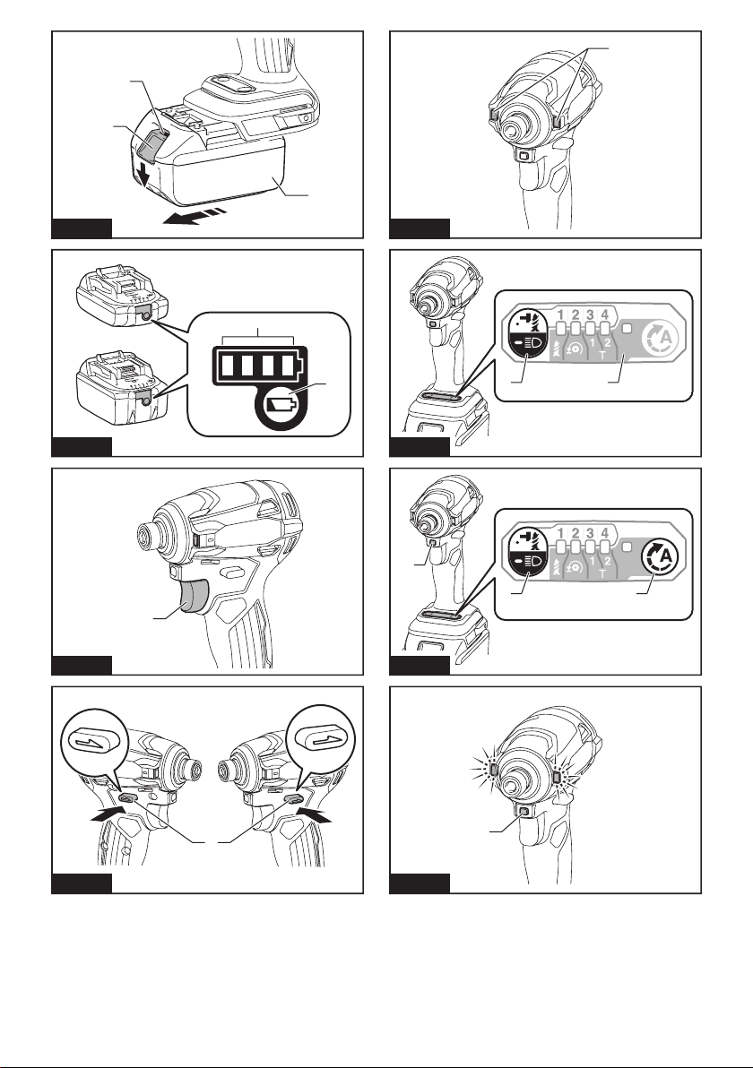
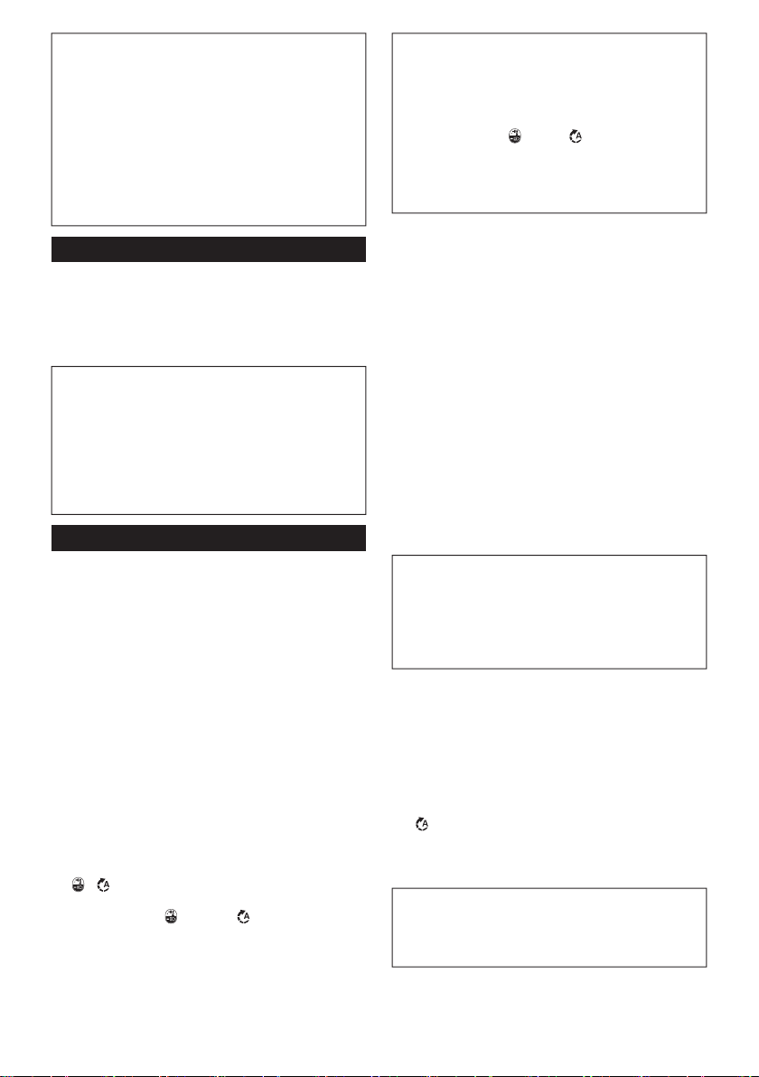
Fig.1: 1. Red indicator 2. Button 3.
while sliding the button on the front of the cartridge.
CAUTION: Always install the battery cartridge
fully until the red indicator cannot be seen. If not,
CAUTION: Do not install the battery cartridge
forcibly.

8ENGLISH
Tool / battery protection system
-
-
placed under one of the following conditions:
Overload protection
-
application that caused the tool to become overloaded.
Then turn the tool on to restart.
Overheat protection
Overdischarge protection
Indicating the remaining battery
capacity
Only for battery cartridges with the indicator
Fig.2: 1. Indicator lamps 2. Check button
-
light up for a few seconds.
Indicator lamps Remaining
capacity
Lighted Blinking
75% to 100%
50% to 75%
25% to 50%
0% to 25%
Charge the
malfunctioned.
NOTE: Depending on the conditions of use and the
NOTE:
Switch action
Fig.3: 1. Switch trigger
CAUTION: Before installing the battery car-
tridge into the tool, always check to see that the
switch trigger actuates properly and returns to
the "OFF" position when released.
trigger. Release the switch trigger to stop.
NOTE:-
ing the switch trigger for about 6 minutes.
NOTE:
buttons do not work.
Reversing switch action
Fig.4: 1. Reversing switch lever
CAUTION: Always check the direction of
rotation before operation.
CAUTION: Use the reversing switch only after
the tool comes to a complete stop. Changing the
-
age the tool.
CAUTION: When not operating the tool,
always set the reversing switch lever to the neu-
tral position.
This tool has a reversing switch to change the direction
of rotation. Depress the reversing switch lever from the
A side for clockwise rotation or from the B side for coun-
terclockwise rotation.
When the reversing switch lever is in the neutral posi-
Electric brake
This tool is equipped with an electric brake. If the tool
released, have the tool serviced at a Makita service center.
Lighting up the front lamp
CAUTION: Do not look in the light or see the
source of light directly.
Fig.5: 1. Front lamp
Fig.6: 1. Button 2. Switch panel
release the switch trigger. The front lamps go out approxi-
hold the button for a few seconds.
trigger. Within 10 seconds after releasing the switch
trigger, press and hold the button for a few seconds.
on even if the trigger is pulled.
To turn on the lamp status again, press and hold the
button for a few seconds.

9ENGLISH
NOTE: When the tool is overheated, the front lamps
again.
NOTE:
when the reversing switch lever is not in the neutral
switch trigger, the lamp status is on. When the front
NOTE:
the front lamps. Be careful not to scratch the lens of
Light mode
To turn on the light, set the reversing switch lever in the
neutral position and pull the switch trigger.
depress the reversing switch lever.
NOTE: You cannot change the application mode
while the light mode is on. The lamps on the switch
panel do not turn on when the light mode is on.
NOTE:
change the application mode when the light mode is
on.
NOTE: The light mode does not work when the tool/
Changing the application mode
What's the application mode?
The application mode is the variation of the driving
This tool features following application modes:
Impact force
• 4 (Max)
• 3 (Hard)
• 2 (Medium)
• 1 (Soft)
Assist type
• Wood mode
• Bolt mode
• T mode (1)
• T mode (2)
-
ton , , or the quick mode-switching button.
Fig.7: 1. Quick mode-switching button
2. Button 3. Button
mode-switching function).
NOTE: When none of the lamp on the panel is lit,
pull the switch trigger once before pressing the quick
mode-switching button.
NOTE: You will not be able to change the application
one minute. In this case, pull the switch trigger
once and press the button, button, or quick
mode-switching button.
NOTE: Refer to "Registering the application mode"
in "Quick mode-switching function" section for how to
register the application mode.
Quick mode-switching button
The function of the quick mode-switching button varies
-
tion mode to the tool.
Fig.8: 1. Quick mode-switching button
When the application mode is not
registered:
the quick mode-switching button. The front lamps on
When the application mode is registered:
The tool switches between the registered application
press the quick mode-switching button. The front lamps
button.
NOTE:
button.
NOTE: Refer to "Registering the application mode"
in "Quick mode-switching function" section for how to
register the application mode.
Disabling the quick mode-switching
button
You can also disable the quick mode-switching button.
After disabling, the quick mode-switching button will not
work for changing the impact force and switching the
application mode.
To disable the quick mode-switching button, press and
hold the quick mode-switching button and the but-
ton at the same time until the all lamps on the panel
blink.
To resume the quick mode-switching button, perform
the same procedure as above again.
NOTE: Registering and erasing the application mode
can be performed even if the quick mode-switching
button is disabled. After registering or erasing the
application mode, the quick mode-switching button
will be activated.

10 ENGLISH
Quick reference
The following table shows the functions of the quick mode-switching button.
indicates the quick mode-switching button.
Button(s) / Purpose Action
(When quick mode-switching function
is OFF)
Changing the impact force by the quick
mode-switching button
Press
(When quick mode-switching function
is ON)
Switching to the registered application
mode
Press
+
Registering the application mode
Press and hold (each button) Example: Wood mode is registered
The lamp of desired application mode
blinks.
+
Erasing the registered application mode
Press and hold (each button)
All impact force grade lamps blink.
+
Disabling/resuming the quick
mode-switching button
Press and hold (each button)
All lamps on the panel blink.
: The lamp is blinking.
Changing the impact force
You can change the impact force in four steps: 4 (max), 3 (hard), 2 (medium), and 1 (soft).
This allows a tightening suitable to the work.
or the quick mode-switching button.
NOTE:-
ton , , or the quick mode-switching button.
Fig.9: 1. Button
Application mode
(Impact force grade
displayed on panel)
Maximum blows Purpose Example of application
4 (Max) 3,800 min-1 (/min) Tightening with the maximum force
and speed.
Driving screws to underwork materi-
als, tightening long screws or bolts.
3 (Hard) 3,600 min-1 (/min) Tightening with less force and speed
than Max mode (easier to control than
Max mode).
Driving screws to underwork materi-
als, tightening bolts.

11 ENGLISH
Application mode
(Impact force grade
displayed on panel)
Maximum blows Purpose Example of application
2 (Medium) 2,600 min-1 (/min)
needed.
plaster boards.
1 (Soft) 1,100 min-1 (/min) Tightening with less force to avoid
screw thread breakage.
Tightening sash screws or small
screws such as M6.
: The lamp is on.
NOTE: When none of the lamp on the panel is lit, pull the switch trigger once before pressing the button or the
quick mode-switching button.
NOTE:
Changing assist type
control.
.
NOTE:, ,
or the quick mode-switching button.
Fig.10: 1. Button
Application mode
(Assist type displayed
on panel)
Maximum blows Feature Purpose
Wood mode * 3,800 min-1 (/min) This mode helps to prevent a screw from falling at
the beginning of driving. The tool drives a screw
to impact, the rotation speed increases and reaches
the maximum speed.
Tightening long screws.
Bolt mode 3,800 min-1 (/min)
When loosening a bolt with the tool driving in coun-
after the bolt/nut gets enough loosened. The stroke
of the switch trigger to reach maximum speed will
become short in this mode.
Loosening bolts.
T mode (1) * –
(The tool stops rotating
soon after impact starts.)
This mode helps to prevent the screws from
over-tightening. It also accomplishes quick oper-
drives a screw with high-speed rotation and stops
soon after the tool starts to impact.
NOTE:
The timing to stop the driving varies depending
on the type of the screw and material to be
driven. Make a test driving before using this
mode.
Driving self-drilling
screws to a thin metal
T mode (2) * 2,600 min-1 (/min) This mode helps to prevent the screws from
breakage and stripping. It also accomplishes quick
drives a screw with high-speed rotation and slows
down the rotation when the tool starts to impact.
NOTE:
Release the switch trigger as soon as the tight-
Driving self-drilling
screws to a thick metal
: The lamp is on.
* When the tool rotates counterclockwise, it rotates same as the 4 (max) mode, 3,800 min-1 (/min).

12 ENGLISH
NOTE: When none of the lamp on the panel is lit, pull the switch trigger once before pressing the button .
NOTE:
Quick mode-switching function
What you can do with the quick mode-switching function
The quick mode-switching function saves the time for changing the application mode of the tool. You can switch to
EXAMPLE
again.
Even if the tool is in other application mode than T mode, pressing the quick mode-switching button changes to
You can choose one of following application modes for quick mode-switching function:
Impact force
• 4 (Max)
• 3 (Hard)
• 2 (Medium)
• 1 (Soft)
Assist type
• Wood mode
• Bolt mode
• T mode (1)
• T mode (2)
Registering application mode
1. With the button or
2. Press and hold the button and the quick mode-switching button at the same time until the lamp of desired
application mode blinks.
Fig.11: 1. Quick mode-switching button 2. Button
NOTE:
Using the quick mode-switching function
When the tool is in the mode that is not registered, press the quick mode-switching button to switch to the registered
-
tered application mode.
The lamp of the registered application mode will blink when using the registered application mode.
Erasing the registered application mode
Press and hold the button and button at the same time until all impact force grade lamps blink.
NOTE: After erasing the registered application mode, the quick mode-switching button works for changing the
impact force.

13 ENGLISH
Indication patterns
Application mode While registering the application mode When the registered application mode
turns on
4 (Max)
3 (Hard)
2 (Medium)
1 (Soft)
Wood mode
Bolt mode
T mode (1)
T mode (2)
: The lamp is on.
: The lamp is blinking.
ASSEMBLY
CAUTION: Always be sure that the tool is
before carrying out any work on the tool.
Installing or removing driver bit/
socket bit
Fig.12
socket bit.
For tool with shallow driver bit hole
A=12mm
B=9mm
bit. Follow the procedure
1. (Note) Bit-piece is not
For tool with deep driver bit hole
A=17mm
B=14mm
bits, follow the procedure 1.
A=12mm
B=9mm
bits, follow the procedure 2.
for installing the bit.
Procedure 1
For tool without one-touch type sleeve
Fig.13: 1. Driver bit 2. Sleeve
To install the driver bit, pull the sleeve in the direction of
the arrow and insert the driver bit into the sleeve as far
as it will go.
Then release the sleeve to secure the driver bit.
For tool with one-touch type sleeve
To install the driver bit, insert the driver bit into the
sleeve as far as it will go.
Procedure 2
In addition to Procedure 1, insert the bit-piece into the
sleeve with its pointed end facing in.
Fig.14: 1. Driver bit 2. Bit-piece 3. Sleeve

14 ENGLISH
To remove the driver bit, pull the sleeve in the direction
of the arrow and pull the driver bit out.
NOTE: If the driver bit is not inserted deep enough
into the sleeve, the sleeve will not return to its original
position and the driver bit will not be secured. In this
-
tions above.
NOTE:
the sleeve and insert it into the sleeve as far as it will
go.
NOTE: After inserting the driver bit, make sure that it
Installing hook
CAUTION: When installing the hook, always
If not, the hook
CAUTION: Use the hanging/mounting parts
for their intended purposes only. Using for unin-
Fig.15: 1. Groove 2. Hook 3. Screw
This can be installed on either side of the tool. To install
the hook, insert it into a groove in the tool housing on
either side and then secure it with a screw. To remove,
loosen the screw and then take it out.
OPERATION
Fig.16
the kind or size of the screw/bolt, the material of the
workpiece to be fastened, etc. The relation between fas-
Proper fastening torque for standard bolt
N•m
(kgf•cm)
M14
M12
M10
M8
M16
M14
M12
M10
M8
M16
140
(1428)
(1224)
(1020)
(816)
(612)
(408)
(204)
120
100
80
60
40
20
01
2
1
2
1. Fastening time (second) 2. Fastening torque
Proper fastening torque for high tensile bolt
2
1
M14
M12
M14
M12
M10
M8
M10
M8
200
180
160
140
120
100
80
60
40
20
0123
(2040)
(1836)
(1632)
(1428)
(1224)
(1020)
(816)
(612)
(408)
(204)
N•m
(kgf•cm)
1. Fastening time (second) 2. Fastening torque
NOTICE: If you use a spare battery to continue
the operation, rest the tool at least 15 min.
NOTE: Use the proper bit for the head of the screw/
NOTE: When fastening M8 or smaller screw, choose
the switch trigger so that the screw is not damaged.
NOTE: Hold the tool pointed straight at the screw.
NOTE:
-
check the torque with a torque wrench.
torque will be reduced.
2. Driver bit or socket bit
Failure to use the correct size driver bit or socket
bit will cause a reduction in the fastening torque.
3. Bolt
•
of bolt are the same, the proper fastening torque
• Even though the diameters of bolts are the
of bolt and the bolt length.
4.
The manner of holding the tool or the material of
5. Operating the tool at low speed will cause a reduc-
tion in the fastening torque.

15 ENGLISH
MAINTENANCE
CAUTION: Always be sure that the tool is
before attempting to perform inspection or
maintenance.
NOTICE: Never use gasoline, benzine, thinner,
alcohol or the like. Discoloration, deformation or
cracks may result.
To maintain product SAFETY and RELIABILITY,
OPTIONAL
ACCESSORIES
CAUTION: These accessories or attachments
are recommended for use with your Makita tool
accessories or attachments might present a risk of
for its stated purpose.
-
Center.
• Driver bits
• Socket bits
• Bit piece
• Hook
• Tool hanger
NOTE:

16 FRANÇAIS
FRANÇAIS (Instructions originales)
SPÉCIFICATIONS
Modèle : DTD172
Capacités de serrage Vis à machine M4 - M8
Boulon standard M5 - M16
Boulon à haute résistance M5 - M14
Vitesse à vide Mode de percussion max. 0 - 3 600 min-1
Mode de percussion rude 0 - 3 200 min-1
0 - 2 100 min-1
Mode de percussion douce 0 - 1 100 min-1
Mode bois 0 - 1 800 min-1
Mode boulon 0 - 3 600 min-1
Mode T (1) 0 - 2 900 min-1
Mode T (2) 0 - 3 600 min-1
Coups par minute Mode de percussion max. 0 - 3 800 min-1
Mode de percussion rude 0 - 3 600 min-1
0 - 2 600 min-1
Mode de percussion douce 0 - 1 100 min-1
Mode bois 0 - 3 800 min-1
Mode boulon 0 - 3 800 min-1
Mode T (1) -
Mode T (2) 0 - 2 600 min-1
Tension nominale 18 V CC
Longueur totale 114 mm
Poids net 1,2 - 1,5 kg
plus lourde, conformément à la procédure EPTA 01/2014, sont indiquées dans le tableau.
Batterie et chargeur applicables
Batterie BL1815N / BL1820B / BL1830B / BL1840B / BL1850B / BL1860B
Chargeur DC18RC / DC18RD / DC18RE / DC18SD / DC18SE / DC18SF /
DC18SH
•
Certains chargeurs et batteries répertoriés ci-dessus peuvent ne pas être disponibles selon la région où vous résidez.
AVERTISSEMENT : N’utilisez que les batteries et les chargeurs répertoriés ci-dessus. L’utilisation
d’autres batteries et chargeurs peut provoquer des blessures et/ou un incendie.
Utilisations
L’outil est conçu pour le vissage dans le bois, le métal
et le plastique.
Bruit
EN62841-2-2 :
Niveau de pression sonore (LpA) : 97 dB (A)
Niveau de puissance sonore (LWA ) : 108 dB (A)
NOTE : La ou les valeurs d’émission de bruit décla-
rées ont été mesurées conformément à la méthode
de test standard et peuvent être utilisées pour com-
parer les outils entre eux.
NOTE : La ou les valeurs d’émission de bruit décla-
rées peuvent aussi être utilisées pour l’évaluation
préliminaire de l’exposition.

17 FRANÇAIS
AVERTISSEMENT : Portez un serre-tête
antibruit.
AVERTISSEMENT : L’émission de bruit
lors de l’usage réel de l’outil électrique peut être
la façon dont l’outil est utilisé, particulièrement
selon le type de pièce usinée.
AVERTISSEMENT : Les mesures de sécurité
à prendre pour protéger l’utilisateur doivent être
basées sur une estimation de l’exposition dans
des conditions réelles d’utilisation (en tenant
compte de toutes les composantes du cycle
d’utilisation, comme par exemple le moment de
sa mise hors tension, lorsqu’il tourne à vide et le
moment de son déclenchement).
Vibrations
Valeur totale de vibrations (somme de vecteur triaxial)
déterminée selon EN62841-2-2 :
Mode de travail : serrage avec impact de vis ou boulon
ne dépassant pas la capacité maximale de l’outil
Émission de vibrations (ah) : 13,5 m/s2
2
NOTE : La ou les valeurs de vibration totales décla-
rées ont été mesurées conformément à la méthode
de test standard et peuvent être utilisées pour com-
parer les outils entre eux.
NOTE : La ou les valeurs de vibration totales décla-
rées peuvent aussi être utilisées pour l’évaluation
préliminaire de l’exposition.
AVERTISSEMENT : L’émission de vibrations
lors de l’usage réel de l’outil électrique peut être
la façon dont l’outil est utilisé, particulièrement
selon le type de pièce usinée.
AVERTISSEMENT : Les mesures de sécurité
à prendre pour protéger l’utilisateur doivent être
basées sur une estimation de l’exposition dans
des conditions réelles d’utilisation (en tenant
compte de toutes les composantes du cycle
d’utilisation, comme par exemple le moment de
sa mise hors tension, lorsqu’il tourne à vide et le
moment de son déclenchement).
Déclaration de conformité CE
Pour les pays européens uniquement
La déclaration de conformité CE est fournie en Annexe
A à ce mode d’emploi.
CONSIGNES DE
SÉCURITÉ
Consignes de sécurité générales
pour outils électriques
AVERTISSEMENT : Veuillez lire les
consignes de sécurité, instructions, illustrations
électrique. Le non-respect de toutes les instructions
indiquées ci-dessous peut entraîner une électrocu-
tion, un incendie et/ou de graves blessures.
Conservez toutes les mises en
garde et instructions pour réfé-
rence ultérieure.
Le terme « outil électrique » dans les avertissements
fait référence à l’outil électrique alimenté par le secteur
(avec cordon d’alimentation) ou à l’outil électrique fonc-
tionnant sur batterie (sans cordon d’alimentation).
Consignes de sécurité pour le
1. Tenez l’outil électrique par des surfaces de
au cours de laquelle la vis ou le boulon peut
Le
-
métalliques exposées de l’outil et électrocuter
l’opérateur.
2.
Ayez toujours une assise ferme sous vos pieds.
Veillez à ce que personne ne se trouve en dessous
de vous quand vous utilisez l’outil en hauteur.
3. Tenez votre outil fermement.
4. Portez un casque anti-bruit.
5. Ne touchez pas l’embout ou la pièce immédia-
tement après le fonctionnement. Ils peuvent
être extrêmement chauds et brûler votre peau.
6. Gardez les mains éloignées des pièces en
rotation.
7. Utilisez la ou les poignées auxiliaires, si l’outil
en possède. Toute perte de maîtrise de l’outil
comporte un risque de blessure.
8. Tenez l’outil électrique par des surfaces de
au cours de laquelle l’accessoire de coupe
sous tension peut transmettre du courant dans les
-
cuter l’opérateur.
9. -
triques, de conduites d’eau, de conduites
de gaz, etc., présentant un risque s’ils sont
endommagés suite à l’utilisation de l’outil.
CONSERVEZ CES
INSTRUCTIONS.

18 FRANÇAIS
AVERTISSEMENT : NE vous laissez PAS
sentiment d’aisance et de familiarité avec le
produit, en négligeant le respect rigoureux des
consignes de sécurité qui accompagnent le pro-
duit en question.
La MAUVAISE UTILISATION de l’outil ou l’igno-
rance des consignes de sécurité indiquées
dans ce mode d’emploi peut entraîner de graves
blessures.
Consignes de sécurité importantes
pour la batterie
1. Avant d’utiliser la batterie, lisez toutes les
instructions et précautions relatives (1) au
chargeur de batterie, (2) à la batterie, et (3) au
produit utilisant la batterie.
2.
batterie. Cela pourrait entraîner un incendie, une
chaleur excessive ou une explosion.
3. Cessez immédiatement l’utilisation si le temps
de fonctionnement devient excessivement
voire d’explosion.
4. Si l’électrolyte pénètre dans vos yeux, rin-
cez-les à l’eau claire et consultez immédiate-
ment un médecin. Il y a risque de perte de la
vue.
5. Ne court-circuitez pas la batterie :
(1) Ne touchez les bornes avec aucun maté-
riau conducteur.
(2) Évitez de ranger la batterie dans un
conteneur avec d’autres objets métal-
liques, par exemple des clous, des pièces
de monnaie, etc.
(3) N’exposez pas la batterie à l’eau ou à la
pluie.
Un court-circuit de la batterie peut provoquer
une intensité de courant élevée, une sur-
panne.
6. Ne rangez ni n’utilisez l’outil et la batterie dans
un endroit où la température risque d’atteindre
ou de dépasser 50 °C.
7. Ne jetez pas la batterie au feu même si elle est
sérieusement endommagée ou complètement
épuisée. La batterie peut exploser au contact
du feu.
8. Abstenez-vous de clouer, couper, écraser,
jeter, laisser tomber la batterie, ou de la heur-
ter contre un objet dur. Cela pourrait entraîner
un incendie, une chaleur excessive ou une
explosion.
9. N’utilisez pas la batterie si elle est
endommagée.
10. Les batteries au lithium-ion contenues sont
soumises aux exigences de la législation sur
les marchandises dangereuses.
Lors du transport commercial par des tierces
parties ou des transitaires par exemple, des exi-
d’emballage doivent être respectées.
Pour la préparation de l’article expédié, il est néces-
saire de consulter un expert en matériau dangereux.
Veuillez également respecter les réglementations
nationales susceptibles d’être plus détaillées.
Recouvrez les contacts exposés avec du ruban adhésif
ou du ruban de masquage et emballez la batterie de telle
sorte qu’elle ne puisse pas bouger dans l’emballage.
11. Lors de la mise au rebut de la batterie, reti-
rez-la de l’outil et jetez-la en lieu sûr. Suivez les
réglementations locales en matière de mise au
rebut des batteries.
12. Utilisez les batteries uniquement avec les
L’insertion de
batteries dans des produits non conformes peut
provoquer un incendie, une chaleur excessive,
13. Lorsque vous n’utilisez pas l’outil pendant une
période prolongée, la batterie doit être retirée
de l’outil.
14.
Pendant et après l’utilisation, la batterie peut
compris en cas de température relativement basse.
Manipulez les batteries chaudes avec précaution.
15. Ne touchez pas la borne de l’outil immédiate-
ment après utilisation car elle peut être assez
chaude pour provoquer des brûlures.
16. Évitez que des copeaux, de la poussière ou
du sol adhèrent aux bornes, aux trous et aux
rainures de la batterie. Cela pourrait réduire les
performances ou casser l’outil ou la batterie.
17. À moins que l’outil prenne en charge un tel
usage, n’utilisez pas la batterie à proximité de
lignes électriques haute tension. Cela pourrait
ou la batterie.
18. Conservez la batterie hors de portée des
enfants.
CONSERVEZ CES INSTRUCTIONS.
ATTENTION : N’utilisez que des batteries
Makita d’origine. L’utilisation de batteries de marque
-
voquer l’explosion des batteries, ce qui présente un
risque d’incendie, de dommages matériels et corpo-
rels. Cela annulera également la garantie Makita pour
l’outil et le chargeur Makita.
Conseils pour assurer la durée
de vie optimale de la batterie
1. Chargez la batterie avant qu’elle ne soit com-
plètement déchargée. Arrêtez toujours l’outil
et rechargez la batterie quand vous remarquez
que la puissance de l’outil diminue.
2. Ne rechargez jamais une batterie complète-
ment chargée. La surcharge réduit la durée de
service de la batterie.
3.
Chargez la batterie à une température ambiante
comprise entre 10 °C et 40 °C. Avant de charger
une batterie chaude, laissez-la refroidir.
4. Lorsque vous n’utilisez pas la batterie, reti-
rez-la de l’outil ou du chargeur.
5. Rechargez la batterie si elle est restée inutili-
sée pendant une période prolongée (plus de
six mois).

19 FRANÇAIS
DESCRIPTION DU
FONCTIONNEMENT
ATTENTION : Assurez-vous toujours que
l’outil est hors tension et que sa batterie est
fonctionnement.
Insertion ou retrait de la batterie
ATTENTION : Éteignez toujours l’outil avant
de mettre en place ou de retirer la batterie.
ATTENTION : Tenez fermement l’outil et la
batterie lors de la mise en place ou du retrait de
la batterie. Si vous ne tenez pas fermement l’outil
et la batterie, ils peuvent vous glisser des mains, et
s’abîmer ou vous blesser.
Fig.1: 1. Indicateur rouge 2. Bouton 3. Batterie
Pour retirer la batterie, faites-la glisser hors de l’outil
tout en faisant glisser le bouton à l’avant de la batterie.
Pour mettre la batterie en place, alignez la languette de
la batterie avec la rainure du compartiment puis insérez
léger déclic indiquant qu’elle est bien en place. Si vous
pouvez voir l’indicateur rouge comme illustré sur la
ATTENTION : Insérez toujours complètement
la batterie jusqu’à ce que l’indicateur rouge ne
soit plus visible. Sinon, elle pourrait tomber acciden-
tellement de l’outil, au risque de vous blesser ou de
ATTENTION : N’insérez pas la batterie de
force. Si elle ne glisse pas facilement, c’est que vous
ne l’insérez pas correctement.
Système de protection de l’outil/la
batterie
-
tation vers le moteur pour prolonger la durée de vie de
l’outil et de la batterie. Si l’outil ou la batterie se trouve
dans l’une des situations suivantes, l’outil cessera
automatiquement de fonctionner.
Protection contre la surcharge
-
quant un appel de courant anormalement élevé, l’outil
s’arrête automatiquement. Dans ce cas, éteignez l’outil
l’outil. Puis rallumez l’outil pour reprendre la tâche.
s’arrête automatiquement et la lampe clignote. Dans
ce cas, laissez l’outil ou la batterie refroidir avant de
rallumer l’outil.
Protection contre la décharge totale
de la batterie
s’arrête automatiquement. Dans ce cas, retirez la batte-
rie de l’outil et chargez-la.
Indication de la charge restante de
la batterie
Uniquement pour les batteries avec voyant
lumineux
Fig.2: 1. Témoins 2.
pour indiquer la charge restante de la batterie. Les
témoins s’allument pendant quelques secondes.
Témoins Charge
restante
Allumé Éteint Clignotant
75 % à 100 %
50 % à 75 %
25 % à 50 %
0 % à 25 %
Chargez la
batterie.
Anomalie
possible
de la batterie.
NOTE : Selon les conditions d’utilisation et la tem-
NOTE :
protection de la batterie.
Fig.3: 1. Gâchette
ATTENTION : Avant d’insérer la batterie dans
-
tionne bien et revient en position d’arrêt lorsque
La vitesse de l’outil augmente à mesure que l’on accroît
la pression exercée sur la gâchette. Pour l’arrêter,
relâchez la gâchette.
NOTE : L’outil s’arrêtera automatiquement si vous
continuez d’enclencher la gâchette pendant 6
minutes environ.
NOTE : Pendant que vous enclenchez la gâchette,
aucun autre bouton ne fonctionne.

20 FRANÇAIS
Fonctionnement de l’inverseur
Fig.4: 1. Levier de l’inverseur
ATTENTION :
rotation avant d’utiliser l’outil.
ATTENTION : N’utilisez l’inverseur qu’une
fois que l’outil est complètement arrêté. Si vous
changez le sens de rotation avant l’arrêt de l’outil,
vous risquez de l’endommager.
ATTENTION : Lorsque vous n’utilisez pas
l’outil, placez toujours le levier de l’inverseur en
position neutre.
le sens de rotation. Enfoncez le levier de l’inverseur
du côté A pour une rotation dans le sens des aiguilles
d’une montre, ou du côté B pour une rotation dans le
sens inverse des aiguilles d’une montre.
Vous ne pouvez pas démarrer l’outil si le levier de l’in-
verseur se trouve en position neutre.
Frein électrique
-
le relâchement de la gâchette, faites réparer l’outil dans
un centre de service Makita.
Allumage de la lampe avant
ATTENTION : Évitez de regarder directement
le faisceau lumineux ou sa source.
Fig.5: 1. Lampe avant
Fig.6: 1. Bouton 2. Tableau de commande
Enclenchez la gâchette pour allumer les lampes avant. Pour
les éteindre, relâchez la gâchette. Les lampes avant s’étei-
Pour éteindre les lampes avant dans les 10 secondes, main-
tenez enfoncé le bouton pendant quelques secondes.
Pour désactiver les lampes avant, désactivez le statut
des lampes. Pour désactiver le statut de la lampe,
enclenchez puis relâchez la gâchette. Dans les 10
enfoncé le bouton pendant quelques secondes.
Lorsque le statut des lampes est désactivé, les lampes avant
ne s’allumeront pas même si la gâchette est enclenchée.
Pour activer à nouveau le statut des lampes, maintenez
enfoncé le bouton pendant quelques secondes.
NOTE :
avant clignotent pendant une minute, puis le tableau
de commande s’éteint. Dans ce cas, laissez refroidir
l’outil avant de le faire fonctionner à nouveau.
NOTE :
-
chez la gâchette lorsque le levier de l’inverseur ne se
trouve pas en position neutre. Si les lampes avant s’allu-
que leur statut est activé. Si les lampes avant ne s’allu-
NOTE :
Retirez la saleté sur la lentille des lampes avant
des lampes avant sous peine de diminuer leur éclairage.
Mode éclairage
Vous pouvez utiliser l’outil comme lampe pratique.
Pour allumer la lampe, réglez le levier de l’inverseur sur
la position neutre et enclenchez la gâchette.
La lampe continue d’éclairer pendant environ une heure.
Pour éteindre la lampe, enclenchez à nouveau la
gâchette ou enfoncez le levier de l’inverseur.
NOTE :-
plication lorsque le mode éclairage est activé. Les
témoins sur le tableau de commande ne s’allument
pas lorsque le mode éclairage est activé.
NOTE : Vous ne pouvez pas activer ou désactiver le
lorsque le mode éclairage est activé.
NOTE : Le mode éclairage ne fonctionne pas lorsque
Changement du mode d’application
Qu’est-ce que le mode d’application ?
Le mode d’application correspond à la variation de la
programmées dans l’outil. En choisissant un mode d’ap-
plication adapté à la tâche, vous pouvez accomplir votre
Cet outil comporte les modes d’application suivants :
Force de percussion
• 4 (Max.)
• 3 (Rude)
• 1 (Douce)
Type d’assistance
• Mode bois
• Mode boulon
• Mode T (1)
• Mode T (2)
-
ton , ou le bouton de changement rapide de
mode.
Fig.7: 1. Bouton de changement rapide de mode
2. Bouton 3. Bouton
En enregistrant un mode d’application donné sur l’outil, il
de mode (fonction de changement rapide de mode) pour
basculer sur le mode d’application enregistré.
NOTE : Si aucun des témoins sur le panneau n’est
allumé, enclenchez la gâchette une fois avant d’ap-
NOTE :-
plication si vous n’utilisez pas l’outil pendant environ
une minute. Dans ce cas, enclenchez la gâchette une
, le bouton ou le
bouton de changement rapide de mode.
NOTE : Consultez « Enregistrement du mode d’ap-
plication » dans la section « Fonction de changement
rapide de mode » pour savoir comment enregistrer le
mode d’application.
Other manuals for DTD172
3
Table of contents
Languages:
Other Makita Impact Driver manuals

Makita
Makita XT281S User manual

Makita
Makita TW0350 User manual

Makita
Makita 6953 User manual

Makita
Makita DTD129 User manual

Makita
Makita XDT09 User manual

Makita
Makita BTD133 User manual

Makita
Makita DOLMAR PS-32C Operating instructions

Makita
Makita tw0200 User manual

Makita
Makita 6904VH User manual

Makita
Makita 6952 User manual

Makita
Makita BTW120SA User manual

Makita
Makita DTL060 User manual

Makita
Makita DTDA040 Series User manual

Makita
Makita TD022D User manual

Makita
Makita DTD148 User manual

Makita
Makita DTD146 User manual

Makita
Makita 6936FDWDE User manual

Makita
Makita DTD137 User manual

Makita
Makita 6903VD User manual

Makita
Makita BTW152 User manual